Ferromagnetic nodal-line metal in monolayer h-InC
Abstract
Based on first-principles calculations, we predict a new two-dimensional ferromagnetic material that exhibits exotic Fermi surface topology. We show that monolayer hexagonal indium carbide (h-InC) is thermodynamically and dynamically stable, and it energetically favors the ferromagnetic ordering of spins. The perfectly planar geometry in two dimensions, together with ferromagnetism, gives rise to a unique opportunity to encounter intriguing electronic properties, captured in the Fermi surface and band topology. We show that multiple nodal lines coexist in momentum space, accompanied by the electron and hole pockets that touch each other linearly at the nodal lines. Inclusion of spin-orbit coupling enriches the magnetic and electronic properties of h-InC. Spin-orbit coupling leads to an easy-plane type magnetocrystalline anisotropy, and the nodal lines can be tuned into topological nodal points, contingent upon the magnetization direction. Symmetry analysis and a tight-binding model are provided to explain the nodal structure of the bands. Our findings suggest h-InC as a new venue for supporting carbon-based magnetism and exotic band topology in two dimensions.
I INTRODUCTION
A striking consequence of symmetry and topology in the electronic structure of materials is the occurrence of a symmetry-protected topological state, such as topological insulators Hasan and Kane (2010); Qi and Zhang (2011). Notably, the protected degenercies of electronic energy bands by nontrivial band topology are of particular interest, leading to the discovery of condensed-matter realizations of fundamental particles, such as Majorana fermions Kitaev (2001); Fu and Kane (2008); Lutchyn et al. (2010), Weyl fermions Wan et al. (2011); Burkov and Balents (2011), and Dirac fermions Young et al. (2012); Wang et al. (2012a). Topological materials can also realize more exotic fermions beyond the conventional form of elementary particles Soluyanov et al. (2015); Wieder et al. (2016); Bradlyn et al. (2016), such as nodal line semimetals Burkov et al. (2011); Kim et al. (2015); Yu et al. (2015). Nodal line semimetals are a class of topological semimetals that are characterized by hosting one-dimensional lines of nodes formed from the conduction and valance bands. There are multiple mechanisms that topologically protect nodal lines associated with different symmetries, including inversion Kim et al. (2015); Ahn et al. (2018), mirror Bian et al. (2016), and nonsymmorphic glide-mirror Carter et al. (2012); Fang et al. (2015) symmetries. More recently, topological semimetals without time-reversal symmetry hosted in magnetic materials have spurred a deal of community interest in finding exotic phenomena, such as tunable nodal points Chang et al. (2018), enhanced anomalous quantum Hall effect Burkov (2014); Kim et al. (2018a).
On the other hand, the recent development of synthesis and characterization techniques for two-dimensional (2D) materials Novoselov et al. (2005); Zhang et al. (2005); Roldán et al. (2017); Wang et al. (2012b); Chhowalla et al. (2013); Jariwala et al. (2014); Yun et al. (2012); Zhu et al. (2011) has led to the exciting discovery of a room-temperature ferromagnet in two dimensions Griffiths (1964); Mermin and Wagner (1966a); De Jongh and Miedema (2001); Vaz et al. (2008). Whereas magnetism is one of the oldest phenomena observed in materials, its realization in a 2D system has remained elusive; it is only recently that convincing evidence of ferromagnetism has been observed in 2D materials, which include thin films of chromium germanium telluride Cr2Ge2Te6 Gong et al. (2017) and chromium triiodide CrI3 Huang et al. (2017). The discovery of these 2D magnetic materials has motivated numerous experimental and theoretical studies Liu et al. (2017); Miao et al. (2018); Bonilla et al. (2018); Lado and Fernández-Rossier (2017); Lin et al. (2017); Kuklin et al. (2018), which have potential implications for future spintronic device applications Wolf (2001); Sander et al. (2017); Sun et al. (2017); Hirohata et al. (2015) and fundamental science Armitage et al. (2018); Zhao et al. (2016); Liu et al. (2008); Yu et al. (2010); Chang et al. (2013); Fert et al. (2013); Nayak et al. (2016); Tang et al. (2016); Watanabe et al. (2018); Sun and Kioussis (2018); Hua et al. ; Zhang et al. (2018).
Apart from these efforts, there have been ongoing studies regarding metal-free magnetism using the localize orbitals of carbon allotropes. According to Lieb’s theorem Lieb (1989), the ground electronic state of a bipartite lattice is accompanied by the electron spin of , where and are the number of sites in the and sublattices, respectively. The crucial requirement for a carbon-based bipartite lattice to induce ferromagnetism is thus to unbalance the number of the orbitals between the two sublattices. This condition enforces two electrons to occupy a single -state near the Fermi level, paying an extra Coulomb repulsion energy , and necessitating spin polarization depending on the strength of with respect to the hopping strength of the electrons Lieb (1989); Anderson (1959); ANDERSON (1987). Considered as possible realizations of Lieb’s condition, diverse carbon allotropes have been investigated based on a variety of schemes Zhou et al. (2009); Nair et al. (2012); Tuček et al. (2016); Błoński et al. (2017); Dai et al. (2014); Červenka et al. (2009); Enoki et al. (2007); Son et al. (2006a); Wu et al. (2009); Wakabayashi et al. (1998); El-Barbary et al. (2003); Ma et al. (2004); Krasheninnikov et al. (2006); Singh and Kroll (2009); Dai et al. (2011); Uchoa et al. (2008); Tuček et al. (2017, 2018); Son et al. (2006b); Jung et al. (2009); Nair et al. (2012); Kopelevich et al. (2000); Esquinazi et al. (2002, 2003); Liu et al. (1998); Saito et al. (1998); González-Herrero et al. (2016).
In this paper we employ the design principle for the bipartite magnetism dictated from Lieb’s theorem to find a new ferromagnetic nodal-line material in two dimensions. We suggest that a single layer of hexagonal indium carbide (h-InC), shown in Fig. 1, should fulfill the Lieb’s condition. Using first-principles calculations, we show that h-InC is a stable ferromagnetic metal, which hosts symmetry-protected twofold-degenerate nodal lines in momentum space, referred to as Weyl nodal lines. Based on the ferromagnetic phase of h-InC, we provide first-principles calculations that establish h-InC as a promising platform for realizing exotic fermiology and potential band topology. In the absence of spin-orbit coupling (SOC), the perfectly planar structure of h-InC allows for the existence of Weyl nodal lines protected by mirror symmetry. We find that different types of nodal lines, respectively referred to as type-I and type-II nodal lines Soluyanov et al. (2015); Li et al. (2017); He et al. ; Kim et al. (2018b); Feng et al. (2017); He et al. , coexist near the Fermi level. The Weyl nodal lines are accompanied with the electron and hole pockets that touch each other linearly at the nodal line. SOC can gap out the Weyl nodal line, or tune to a pair of nodal points, depending on magnetization orientation. The nodal points are topological, characterized by the Berry phase. Considered as a 2D descendant of a three-dimensional Weyl node, which is described by a massless two-band Weyl-like Hamiltonian, the nodal point is often referred to as a 2D Weyl node. We provide symmetry analysis that offers the rationales for the presence and protection of the nodal structure, which is further supported by our a tight-binding theory. The new insight from this work could lead to the discovery of a new 2D material that allows for tunable band topology via the magnetization.
II METHODS
In the present study, we performed first-principles calculations based on density functional theory (DFT) as implemented in the Vienna ab initio simulation package (VASP) Kresse and Furthmuller (1996) within the projector-augmented-plane-wave (PAW) method Blöchl (1994); Kresse and Joubert (1999). The exchange-correlation energy was calculated within the Perdew-Burke-Ernzerholf-type generalized gradient approximation Perdew et al. (1996). The of -grid were sampled from the first Brillouin zone (BZ) using the gamma-centered Monkhorst-Pack scheme Monkhorst and Pack (1976). The plane wave basis was constructed within the energy cutoff of 550 eV. The two-dimensional (2D) crystal structure was approximated by placing a vacuum space of 20 Å along the out-of-plane -direction. The convergence thresholds for the energy and the Hellmann-Feynman force were set to eV and eV/Å, respectively. The phonon calculations were carried out by using the Phonopy package Atsushi Togo (2015). The spin-polarized (spin-unpolarized) phononic energy spectra were calculated within the force criterion of eV/Å using a 441 (661) supercell and the 661 Monkhorst-Pack sampling of -points. The cohesive energy of h-InC was calculated using , where , and are the total energies of h-InC, C, and In, respectively. is the number of atoms per unit cell. The magnetic anisotropy energy of h-InC was calculated based on , where is the total energy evaluated by constraining the direction of the magnetic moments along within the magnetic force theorem method Liechtenstein et al. (1987); Daalderop et al. (1990) implemented in VASP Steiner et al. (2016). To topologically characterize the 2D Weyl points, the Berry phases were calculated via the wannierization of DFT bands using the Wannier90 Marzari et al. (2012) code.
III Results and Discussion
III.1 Atomic structure and structural stability of h-InC
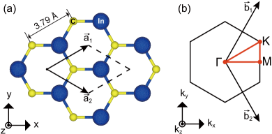
We begin our study by delineating the crystal structure of h-InC. Geometry optimization leads to the planar 2D honeycomb structure shown in Fig. 1(a) with the primitive unit cell comprising one InC formula unit. The space group of h-InC is (# 187). The generating point group of is isomorphic to , which contains mirror symmetry () about the - (-) plane. As shown in detail later, () plays an important role to protect nodal lines (nodal points) of the electronic energy bands. The lattice constant is calculated as = 3.79 Å. Note that the nearest-neighboring C atoms are separated by 3.79 Å, which is much greater than the case of graphene (1.42 Å). This large spacing between carbons helps electrons localized at the C orbitals, thereby promoting spin-polarization.
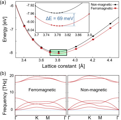
We expect that the h-InC lattice is thermodynamically and kinetically stable. The reason for this follows. First, the cohesive energy of h-InC is calculated as -3.91 eV per atom. This value is comparable to those of known 2D materials, such as silicene (-3.96 eV), germanene (-2.6 eV) Ding and Wang (2015), as well as existing monolayer transition metal dichalcogenides, including MoTe2 and WSe2 (-4 -6 eV) Kang et al. (2013); Ataca and Ciraci (2011); Fan et al. (2015); Torun et al. (2016); Kan et al. (2015). Moreover, the h-InC lattice forms a local minimum in atomic configuration space as shown in the total energy curve in Fig. 4(a), which supports that h-InC is thermodynamically stable. In addition to the thermodynamic stability, the kinetic stability of h-InC is also expected from our phononic energy calculations. Figure 2(b) shows the phononic energy spectra calculated with and without spin-polarization. Both results produce no negative mode, irrespective of spin-polarization, which establish the structural stability of h-InC.
III.2 Magnetism of h-InC
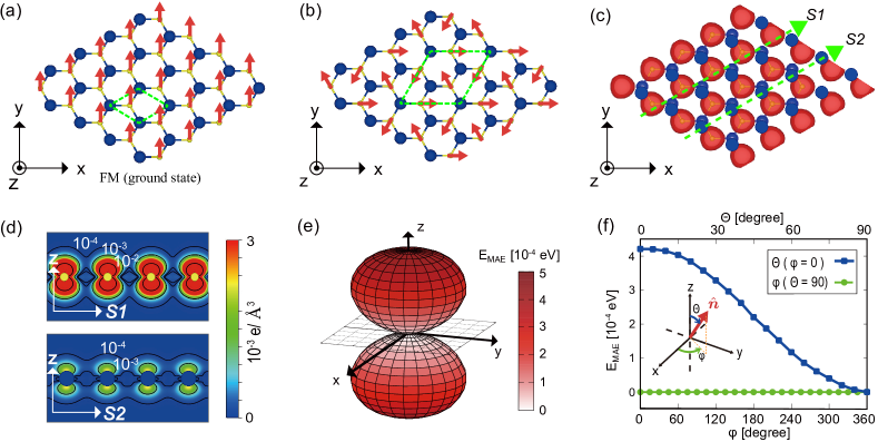
Having discussed the atomic structure of h-InC, we now turn to its magnetic properties. We first evidence that h-InC has the ferromagnetic ground state. After many trials to minimize the total energy of the system with different spin configurations, including the coplanar 120∘ antiferromagnetic configuration shown in Fig. 3(b), we find that the ferromagnetic spin configuration in Fig. 3(a) results in the lowest total energy. In detail, the total energy per unit cell of the ferromagnetic state is calculated as 69 meV lower per carbon atom than the non-magnetic state [See Fig. 2(a)]. With respect to the coplanar 120∘ antiferromagnetic spin configuration shown in the right panel of Fig. 3(a), the energy of the ferromagnetic state is 34 meV lower per carbon atom. As we will show below, spins are localized at carbon atoms that form a triangular sublattice, in which geometric frustration forbids the colinear 180∘ antiferromagnetic spin configuration to become a ground spin state.
We explain the ferromagnetic ground state of h-InC as being due to the unbalanced electrons. As an element in group XIII (main group III) of the periodic table, In provides one less valence electrons than C per unit cell. In this respect, h-InC can be viewed as In-substituted graphene, in which one sublattice of graphene is substituted with In atoms. The In-substitution plays a role to remove half of the electrons of graphene, which necessitates the spin-polarization fulfilling Lieb’s magnetization condition. Indeed, the net spin moment of the ferromagnetic ground state is calculated as 0.8 per unit cell, which is close to 1 that we expected from Lieb’s theorem. Moreover, the magnetization density, shown in Fig. 3(c), shows that a large amount of spins are localized at the carbon sites, which indicate that carbon atoms mainly contribute to the spin moment. The cross-sectional views of the magnetization density in Fig. 3(d) further reveal that the magnetization density originates from the electrons in the carbon orbitals, featuring the orbital characters. Therefore, carbon-based magnetism is considered to be at the heart of the magnetism of h-InC.
In the presence of SOC, h-InC exhibits a weak magnetocrystalline anisotropy of an easy-plane type. Figure 3(e) shows the magnetic anisotropy energy of h-InC evaluated as a function of the azimuth angle measured from the out-of-plane axis and the horizontal azimuth angle measured on the basal plane [See inset of Fig. 3(f)]. The result shows that has the minimum at with a negligible dependence on , thus leading to the formation of (0001) easy plane and in-plane isotropic. The (out-of-plane) hard axis energy is amount to 0.4 meV, as shown in Fig. 3(f). The in-plane isotropy could make the ferromagnetic phase susceptible to thermal fluctuation Mermin and Wagner (1966b) and correspondingly difficult to realize a 2D magnet at finite temperature using h-InC.
III.3 Electronic structure of h-InC
III.3.1 Electronic band structure and PDOS without SOC
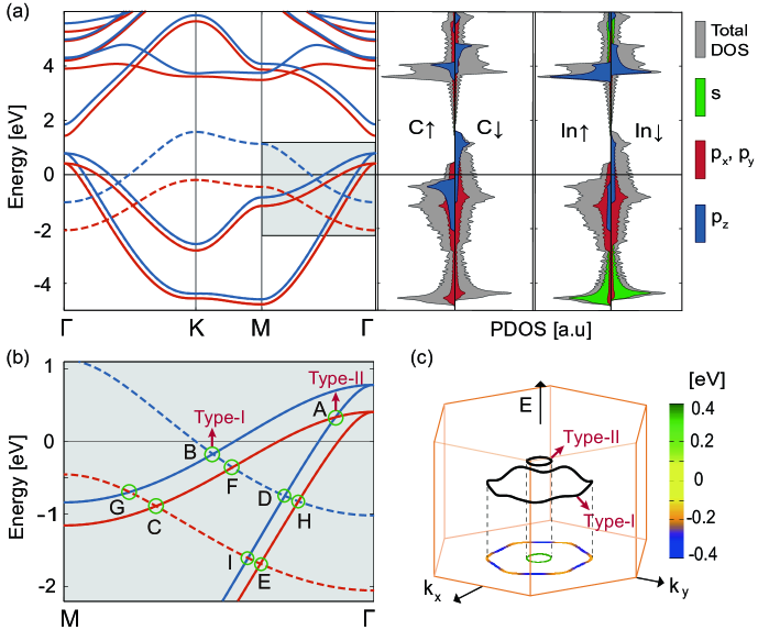
Having predicted the existence of a new 2D magnetic material, we turn to the characterization of its electronic structure. It is readily noticed that h-InC is a spin-polarized metal from its electronic energy band structure presented in Fig. 4(a). The Fermi level () intersects with the spin-polarized energy bands. Notably, the largest spin-splitting occurs between the C bands that correspond to the energy bands containing the two highest occupied energy levels at the point, depicted by dashed lines in Figs. 4(a) and 4(b). The projected density of states (PDOS) in the right panel of Fig. 4(a) further reveal that these energy bands mainly consist of the C orbitals, giving rise to the strong PDOS peaks at eV from the spin-up band and at eV from the spin-down band. As expected, these C bands have relatively a narrow bandwidth within 1.8 eV, reflecting the hindered electron hopping between the C orbitals due to the interstitial In atoms.
The PDOS further reveal that all the other energy bands except the C bands near the Fermi level consist of the , , and orbitals from both C and In atoms. In detail, the bonding states of the orbitals are located deep inside the occupied region of the energy bands near -10 eV, whereas the anti-bonding states of the -orbitals are placed above the Fermi level near 1.43 eV and 1.9 eV at the point. In addition, the strong PDOS peaks appear right below the Fermi level, contributed from the and orbitals of both C and In as well as with a sizable contribution from the In and C orbitals. This indicates that bonds are formed between the -type orbitals of In and C. Hereafter we refer to these bands as bands. Note that the () bands are symmetric (anti-symmetric) under the mirror operation , as they are formed from the , , and () orbitals.
| Node | () | () | nodal line |
|---|---|---|---|
| A | ( , ) | ( , ) | Type-II |
| B | ( , ) | ( , ) | Type-I |
| C | ( , ) | ( , ) | Type-I |
| D | ( , ) | ( , ) | Type-I |
| E | ( , ) | ( , ) | Type-I |
| F | ( , ) | ( , ) | Type-I |
| G | ( , ) | ( , ) | Type-I |
| H | ( , ) | ( , ) | Type-I |
| I | ( , ) | ( , ) | Type-I |
The energy bands with different mirror eigenvalues () can cross each other without opening a band gap as shown in Figs. 4(a) and 4(b). A mirror band (, solid line) intersects with a mirror band (, dashed line). Similarly, the energy bands with different spin states () can also overlap each other without opening a band gap; a spin-up band (, colored by red) crosses a spin-down band (, colored by blue). Thereby, the mirror and spin-rotational symmetries independently protect the nodal structure of the energy bands, and all the band crossings in Fig. 4(c) are explained based on the mirror and spin eigenvalues. For example, protected by mirror symmetry , the band crossings at B, C, D, and E in Fig. 4(c) are formed from the energy bands with the same spin state. Table 1 lists the mirror and spin eigenvalues for the bands that form the nodal points that are introduced in Fig. 4(b).
III.3.2 Weyl nodal lines and Fermi surface topology
Being preserved independently without SOC, the mirror and spin-rotational symmetries are global symmetries in momentum space in the sense that they are respected at any point of the entire BZ. Therefore, the occurrence of band crossings that we found from the band structure signals the existence of one-dimensional nodal lines in the 2D BZ. A close inspection has found multiple nodal lines, such as shown in Fig. 4(d). Notably, the nodal line that contains the band crossing A in Fig. 4(c) is of a unique type, referred to as a type-II nodal line formed from the energy bands that have the same band velocities along the nodal linesLi et al. (2017); Kim et al. (2018b). Note that the () bands have a positive (negative) band curvature at . While conventional type-I nodal lines are formed dominantly from overlapping one band and one band, a type-II nodal line coexists, formed from the overlapping two bands in the energy range from 0.345 eV to 0.348 eV.
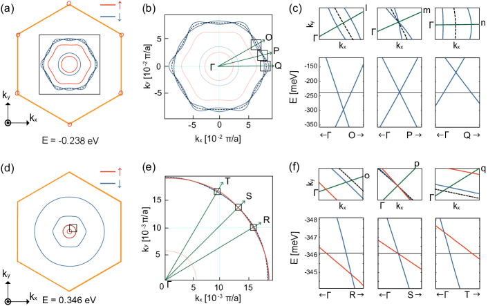
We find a contrasting behavior between the type-I and type-II nodal lines, featured in the Fermi surface geometry. In the type-I case, an alternating chain of electron and hole pockets appears such that the position of the nodal line is placed inside the chain; in contrast, in the type-II case, a chain of electron and hole pockets occurs avoiding the position of the nodal line. Note that in both cases, the electron and hole pockets exist and touch each other linearly at the nodal line. Figures 5(a) and 5(d) illustrate the Fermi surface diagrams at eV and eV, where type-I and type-II nodal lines occur, respectively. They demonstrate that the nodal line that is represented by a dashed line in Fig. 5(b) [(e)] is located at the interior (exterior) part of the area surrounded by the Fermi surfaces that are represented by solid contours. Note that the Fermi surfaces are warped hexagonally around the point. The hexagonal warping is more prominent in the type-I nodal line in Fig. 5(b) than the type-II nodal line in Fig. 5(e), which is due to the type-II nodal line residing closer to the point.
We propose the contrasting geometry of the Fermi surfaces as a generic feature of the type-I and type-II nodal lines in two dimensions, originated from the hexagonal warping and the different signs of the band velocities. To demonstrate this, we plot the energy bands in momentum space along the , , and lines in Fig. 5(c). We first notice that the energy disperses along the nodal line due to the hexagonal warping. The figures show that the band crossing on the () line is shifted down (up) in energy with respect to the Fermi energy (), forming an electron (hole) pocket, whereas the band crossing point occurs at the Fermi energy on . Thus, from to through , the electron pocket is reduced to the crossing point, and evolves to the hole pocket. Meanwhile, the different signs of the band velocity necessitates the occurrence of the crossing points in the inner area of the two Fermi surfaces. Similarly, from to through for the Fermi surfaces at eV, where the type-II nodal line occurs [See Fig. 5(e).], an electron pocket evolves to a hole pocket via a band crossing point. Note that the weaker warping of the energy bands results in a weaker energy dispersion along the type-II nodal line with respect to the type-I nodal line. Moreover, unlike the type-I case, in the type-II case, the same sign of the band velocities necessitate the occurrence of the type-II crossing points in the outer area of the two Fermi surfaces as illustrated in Fig. 5(f). These contrasting patterns of the Fermi surfaces are intrinsic to the very definition of the type-I/type-II classification, done based the band velocities, thus characterizing the types of the nodal lines in two dimensions. We expect that the characteristic feature should be observable in h-InC as in the case of topological nodal lines in three dimensions Mikitik and Sharlai (1999, 2004, 2006, 2007); Hubbard et al. (2011); Mikitik and Sharlai (2014); Yu et al. (2017) and type-II Weyl nodes in topological semimetals Autès et al. (2016); Deng et al. (2016); Yu et al. (2016).
III.3.3 Effect of spin-orbit coupling
| Node | () | () | SOC gap(eV) | Nodal line | ||
|---|---|---|---|---|---|---|
| A | ( , ) | ( , ) | Type-II | |||
| B | ( , ) | ( , ) | Type-I | |||
| C | ( , ) | ( , ) | Type-I | |||
| D | ( , ) | ( , ) | Type-I | |||
| E | ( , ) | ( , ) | Type-I | |||
| F | ( , ) | ( , ) | 0.11 | |||
| G | ( , ) | ( , ) | 0.06 | |||
| H | ( , ) | ( , ) | 0.07 | |||
| I | ( , ) | ( , ) | 0.05 |
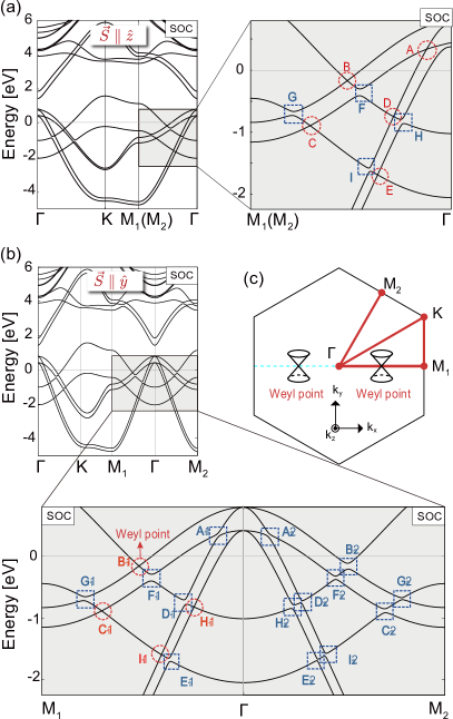
In general, SOC couples the spin and orbital sectors of the Bloch states, such that the nodal lines that we found without SOC can be annihilated. The nodal lines only survive when they are protected by a global symmetry that is respected in the entire BZ even in the presence of SOC. An example is the mirror symmetry with respect to the basal plane , which is preserved only when spins are colinearly aligned along the out-of-plane -direction when including SOC. In this particular case of spin configuration, the nodal lines can survive when they are formed from the energy bands with distinct mirror eigenvalues. Inclusion of SOC necessitates the definition of a new mirror quantum number capable of protecting the band crossings. Some nodal lines indeed survive in our first-principles calculations calculated by constraining the spin orientation along the out-of-plane direction as shown in Fig. 6(a). While the nodal lines that contain the crossings A, B, C, D, or E survive [See Fig. 4(b) and Fig. 6(a)], the other nodal lines that contain F, G, H, or I are gaped out by including SOC. These results are in good agreement with the calculated mirror eigenvalues of the corresponding band, listed in Table 2.
In contrast to the out-of-plane spin-polarization, when spins are aligned uniaxially along an in-plane direction, which is the energetically most favored, the nodal lines are expected to disappear, except for the case where spins are all aligned along -direction. In this particular case, the mirror-symmetry is preserved and the nodal lines that we found without SOC are tuned to 2D Weyl points, residing along the mirror symmetric line (). The DFT band structure in Fig. 6(b), which is calculated by constraining spins along the -direction, exhibits the Weyl points at B1, C1, and H1 along the -invariant line. In contrast, all the nodes in the line, where is broken, open a gap. We note that the Weyl points are topological in the sense that they carry the Berry phase . We confirmed that the Weyl point B1 gives rise to the Berry phase when calculated along the closed path of radius 0.0038 Å-1 that encircles B1.
III.3.4 Tight-binding theory of h-InC
Finally, we construct a tight-binding theory that describes the and -orbitals of C and In of h-InC. These orbitals are responsible for the electronic structure of h-InC near the Fermi energy. The underlying interactions that give rise to the low-energy band structure obtained from the first-principles calculations can essentially be ascribed to 1) the kinetic energy term , contributed from both the nearest and next-nearest neighbor hopping of the valence electrons, 2) on-site energy term for both the electrons that are bound to each sublattice, 3) the effective Zeeman term , which is constructed to discern the sites and the spins, and 4) the SOC term , summarizing
| (1) |
where
Here, and describe the orbital and sublattice indices, respectively. and represent spin states, respectively. and are hopping parameters for the nearest and the next nearest neighbor hopping, respectively. describes the site-dependent Zeeman splitting for bands and bands. In the SOC Hamiltonian , is the orbital angular momentum in the -orbital basis. describes the -orbitals for spin and sublattice .
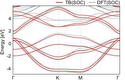
Figure 7 shows the calculated tight-binding bands compared with the DFT bands, where the effective Zeeman field is applied along the out-of-plane -direction. We find that the next nearest-neighbor hopping between -orbitals is indispensable for reproducing hexagonal warping of the Fermi surface. The hexagonal warping results in the dispersion of energy along the nodal lines, allowing for the formation of the electron and hole pockets. The energy bands nicely reproduce the essential features of the first-principles results, especially the nodal structure. The symmetry analysis is also in good agreement with the first-principles results, which supports that our symmetry analysis is valid.
IV Conclusion
In summary, we have performed first-principles calculations to investigate the atomic, magnetic, and electronic structures of monolayer hexagonal indium carbide (h-InC), which realizes a stable ferromagnetic nodal-line metal. Without spin-orbit coupling, we found that doubly degenerate nodal lines are formed from spin-polarized bands. Both the type-I and type-II nodal line coexist, each of which is characterized by a distinctive pattern of the Fermi surface geometry. In the presence of SOC, an easy-plane type magnetocrystalline anisotropy arises for the ferromagnetic state. In addition, SOC provided an opportunity to tune the nodal lines to the topological Weyl points via the engineering the direction of spin-polarization, which might be potentially useful for the future device related with spins. Moreover, the unique Fermi surface topology, accompanied by the coexisting type-I and type-II nodal lines, can give rise to interesting consequence related with quantum oscillations.
Acknowledgements.
This work was supported by the Sungkyun Research Fund 2017 from Sungkyunkwan University. The computational resource was provided from the Korea Institute of Science and Technology Information (KISTI).References
- Hasan and Kane (2010) M. Z. Hasan and C. L. Kane, Rev. Mod. Phys. 82, 3045 (2010).
- Qi and Zhang (2011) X.-L. Qi and S.-C. Zhang, Rev. Mod. Phys. 83, 1057 (2011).
- Kitaev (2001) A. Y. Kitaev, Physics-Uspekhi 44, 131 (2001).
- Fu and Kane (2008) L. Fu and C. L. Kane, Phys. Rev. letters 100, 096407 (2008).
- Lutchyn et al. (2010) R. M. Lutchyn, J. D. Sau, and S. DasSarma, Phys. Rev. letters 105, 077001 (2010).
- Wan et al. (2011) X. Wan, A. M. Turner, A. Vishwanath, and S. Y. Savrasov, Phys. Rev. B 83, 205101 (2011).
- Burkov and Balents (2011) A. A. Burkov and L. Balents, Phys. Rev. letters 107, 127205 (2011).
- Young et al. (2012) S. M. Young, S. Zaheer, J. C. Y. Teo, C. L. Kane, E. J. Mele, and A. M. Rappe, Phys. Rev. Lett. 108, 140405 (2012).
- Wang et al. (2012a) Z. Wang, Y. Sun, X.-Q. Chen, C. Franchini, G. Xu, H. Weng, X. Dai, and Z. Fang, Phys. Rev. B 85, 195320 (2012a).
- Soluyanov et al. (2015) A. A. Soluyanov, D. Gresch, Z. Wang, Q. Wu, M. Troyer, X. Dai, and B. A. Bernevig, Nature 527, 495 (2015).
- Wieder et al. (2016) B. J. Wieder, Y. Kim, A. M. Rappe, and C. L. Kane, Phys. Rev. Lett. 116, 186402 (2016).
- Bradlyn et al. (2016) B. Bradlyn, J. Cano, Z. Wang, M. G. Vergniory, C. Felser, R. J. Cava, and B. A. Bernevig, Science 353 (2016).
- Burkov et al. (2011) A. A. Burkov, M. D. Hook, and L. Balents, Phys. Rev. B 84, 235126 (2011).
- Kim et al. (2015) Y. Kim, B. J. Wieder, C. L. Kane, and A. M. Rappe, Phys. Rev. Lett. 115, 036806 (2015).
- Yu et al. (2015) R. Yu, H. Weng, Z. Fang, X. Dai, and X. Hu, Phys. Rev. letters 115, 036807 (2015).
- Ahn et al. (2018) J. Ahn, D. Kim, Y. Kim, and B.-J. Yang, Phys. Rev. letters 121, 106403 (2018).
- Bian et al. (2016) G. Bian, T.-R. Chang, R. Sankar, S.-Y. Xu, H. Zheng, T. Neupert, C.-K. Chiu, S.-M. Huang, G. Chang, I. Belopolski, D. S. Sanchez, M. Neupane, N. Alidoust, C. Liu, B. Wang, C.-C. Lee, H.-T. Jeng, C. Zhang, Z. Yuan, S. Jia, A. Bansil, F. Chou, H. Lin, and M. Z. Hasan, Nat. Commun. 7 (2016).
- Carter et al. (2012) J.-M. Carter, V. V. Shankar, M. A. Zeb, and H.-Y. Kee, Phys. Rev. B 85, 115105 (2012).
- Fang et al. (2015) C. Fang, Y. Chen, H.-Y. Kee, and L. Fu, Phys. Rev. B 92, 081201(R) (2015).
- Chang et al. (2018) G. Chang, B. Singh, S.-Y. Xu, G. Bian, S.-M. Huang, C.-H. Hsu, I. Belopolski, N. Alidoust, D. S. Sanchez, H. Zheng, H. Lu, X. Zhang, Y. Bian, T.-R. Chang, H.-T. Jeng, A. Bansil, H. Hsu, S. Jia, T. Neupert, H. Lin, and M. Z. Hasan, Phys. Rev. B 97, 041104(R) (2018).
- Burkov (2014) A. A. Burkov, Phys. Rev. Lett. 113, 187202 (2014).
- Kim et al. (2018a) K. Kim, J. Seo, E. Lee, K.-T. Ko, B. Kim, B. G. Jang, J. M. Ok, J. Lee, Y. J. Jo, W. Kang, et al., Nature materials 17, 794 (2018a).
- Novoselov et al. (2005) K. S. Novoselov, A. K. Geim, S. V. Morozov, D. Jiang, M. I. Katsnelson, I. V. Grigorieva, S. V. Dubonos, and A. A. Firsov, Nature 438, 197 (2005).
- Zhang et al. (2005) Y. Zhang, Y.-W. Tan, H. L. Stormer, and P. Kim, Nature 438, 201 (2005).
- Roldán et al. (2017) R. Roldán, L. Chirolli, E. Prada, J. A. Silva-Guillén, P. San-Jose, and F. Guinea, Chemical Society Reviews 46, 4387 (2017).
- Wang et al. (2012b) Q. H. Wang, K. Kalantar-Zadeh, A. Kis, J. N. Coleman, and M. S. Strano, Nat. Nanotechnol. 7, 699 (2012b).
- Chhowalla et al. (2013) M. Chhowalla, H. S. Shin, G. Eda, L.-J. Li, K. P. Loh, and H. Zhang, Nat. Chem. 5, 263 (2013).
- Jariwala et al. (2014) D. Jariwala, V. K. Sangwan, L. J. Lauhon, T. J. Marks, and M. C. Hersam, ACS Nano 8, 1102 (2014).
- Yun et al. (2012) W. S. Yun, S. W. Han, S. C. Hong, I. G. Kim, and J. D. Lee, Phys. Rev. B. 85, 033305 (2012).
- Zhu et al. (2011) Z. Zhu, Y. Cheng, and U. Schwingenschlögl, Phys. Rev. B. 84, 153402 (2011).
- Griffiths (1964) R. B. Griffiths, Phys. Rev. 136, A437 (1964).
- Mermin and Wagner (1966a) N. D. Mermin and H. Wagner, Phys. Rev. Lett. 17, 1133 (1966a).
- De Jongh and Miedema (2001) L. De Jongh and A. Miedema, Adv. Phys. 50, 947 (2001).
- Vaz et al. (2008) C. Vaz, J. Bland, and G. Lauhoff, Rep. Prog. Phys. 71, 056501 (2008).
- Gong et al. (2017) C. Gong, L. Li, Z. Li, H. Ji, A. Stern, Y. Xia, T. Cao, W. Bao, C. Wang, Y. Wang, Z. Q. Qiu, R. J. Cava, S. G. Louie, J. Xia, and X. Zhang, Nature 546, 265 (2017).
- Huang et al. (2017) B. Huang, G. Clark, E. Navarro-Moratalla, D. R. Klein, R. Cheng, K. L. Seyler, D. Zhong, E. Schmidgall, M. A. McGuire, D. H. Cobden, W. Yao, D. Xiao, P. Jarillo-Herrero, and X. Xu, Nature 546, 270 (2017).
- Liu et al. (2017) B. Liu, Y. Zou, S. Zhou, L. Zhang, Z. Wang, H. Li, Z. Qu, and Y. Zhang, Sci. Rep. 7, 6184 (2017).
- Miao et al. (2018) N. Miao, B. Xu, L. Zhu, J. Zhou, and Z. Sun, J. Am. Chem. Soc. 140, 2417 (2018).
- Bonilla et al. (2018) M. Bonilla, S. Kolekar, Y. Ma, H. C. Diaz, V. Kalappattil, R. Das, T. Eggers, H. R. Gutierrez, M.-H. Phan, and M. Batzill, Nat. Nanotechnol. , 289 (2018).
- Lado and Fernández-Rossier (2017) J. L. Lado and J. Fernández-Rossier, 2D Mater. 4, 035002 (2017).
- Lin et al. (2017) G. T. Lin, H. L. Zhuang, X. Luo, B. J. Liu, F. C. Chen, J. Yan, Y. Sun, J. Zhou, W. J. Lu, P. Tong, Z. G. Sheng, Z. Qu, W. H. Song, X. B. Zhu, and Y. P. Sun, Phys. Rev. B 95, 245212 (2017).
- Kuklin et al. (2018) A. V. Kuklin, S. A. Shostak, and A. A. Kuzubov, J. Phys. Chem. Lett. 9, 1422 (2018).
- Wolf (2001) S. A. Wolf, Science 294, 1488 (2001).
- Sander et al. (2017) D. Sander, S. Valenzuela, D. Makarov, C. Marrows, E. Fullerton, P. Fischer, J. McCord, P. Vavassori, S. Mangin, P. Pirro, et al., J. Phys. D 50, 363001 (2017).
- Sun et al. (2017) Y. Sun, Z. Zhuo, X. Wu, and J. Yang, Nano Letters 17, 2771 (2017).
- Hirohata et al. (2015) A. Hirohata, H. Sukegawa, H. Yanagihara, I. Žutić, T. Seki, S. Mizukami, and R. Swaminathan, IEEE Trans. Magn. 51, 1 (2015).
- Armitage et al. (2018) N. P. Armitage, E. J. Mele, and A. Vishwanath, Rev. Mod. Phys. 90, 015001 (2018).
- Zhao et al. (2016) J. Zhao, R. Yu, H. Weng, and Z. Fang, Phys. Rev. B 94, 195104 (2016).
- Liu et al. (2008) C.-X. Liu, X.-L. Qi, X. Dai, Z. Fang, and S.-C. Zhang, Phys. Rev. Lett. 101, 146802 (2008).
- Yu et al. (2010) R. Yu, W. Zhang, H.-J. Zhang, S.-C. Zhang, X. Dai, and Z. Fang, Science 329, 61 (2010).
- Chang et al. (2013) C.-Z. Chang, J. Zhang, X. Feng, J. Shen, Z. Zhang, M. Guo, K. Li, Y. Ou, P. Wei, L.-L. Wang, et al., Science , 167 (2013).
- Fert et al. (2013) A. Fert, V. Cros, and J. Sampaio, Nat. Nanotechnol. 8, 152 (2013).
- Nayak et al. (2016) A. K. Nayak, J. E. Fischer, Y. Sun, B. Yan, J. Karel, A. C. Komarek, C. Shekhar, N. Kumar, W. Schnelle, J. Kübler, et al., Sci. Adv. 2, e1501870 (2016).
- Tang et al. (2016) P. Tang, Q. Zhou, G. Xu, and S.-C. Zhang, Nat. Phys. 12, 1100 (2016).
- Watanabe et al. (2018) H. Watanabe, H. C. Po, and A. Vishwanath, Science Advances 4, eaat8685 (2018).
- Sun and Kioussis (2018) Q. Sun and N. Kioussis, Phys. Rev. B. 97, 094408 (2018).
- (57) G. Hua, S. Nie, Z. Song, R. Yu, G. Xu, and K. Yao, 1801.02806 .
- Zhang et al. (2018) J. Zhang, B. Zhao, T. Zhou, Y. Xue, C. Ma, and Z. Yang, Phys. Rev. B. 97, 085401 (2018).
- Lieb (1989) E. H. Lieb, Phys. Rev. Lett. 62, 1201 (1989).
- Anderson (1959) P. W. Anderson, Phys. Rev. 115, 2 (1959).
- ANDERSON (1987) P. W. ANDERSON, Science 235, 1196 (1987).
- Zhou et al. (2009) J. Zhou, Q. Wang, Q. Sun, X. Chen, Y. Kawazoe, and P. Jena, Nano Lett. 9, 3867 (2009).
- Nair et al. (2012) R. Nair, M. Sepioni, I.-L. Tsai, O. Lehtinen, J. Keinonen, A. Krasheninnikov, T. Thomson, A. Geim, and I. Grigorieva, Nat. Phys. 8, 199– (2012).
- Tuček et al. (2016) J. Tuček, P. Błoński, Z. Sofer, P. Šimek, M. Petr, M. Pumera, M. Otyepka, and R. Zbořil, Adv. Mater. 28, 5045 (2016).
- Błoński et al. (2017) P. Błoński, J. Tuček, Z. Sofer, V. Mazánek, M. Petr, M. Pumera, M. Otyepka, and R. Zbořil, J. Am. Chem. Soc. 139, 3171 (2017).
- Dai et al. (2014) Q. Dai, Y. Zhu, and Q. Jiang, Phys. Chem. Chem. Phys. 16, 10607 (2014).
- Červenka et al. (2009) J. Červenka, M. Katsnelson, and C. Flipse, Nat. Phys. 5, 840 (2009).
- Enoki et al. (2007) T. Enoki, Y. Kobayashi, and K.-I. Fukui, Int. Rev. Phys. Chem. 26, 609 (2007).
- Son et al. (2006a) Y.-W. Son, M. L. Cohen, and S. G. Louie, Phys. Rev. Lett. 97, 216803 (2006a).
- Wu et al. (2009) F. Wu, E. Kan, H. Xiang, S.-H. Wei, M.-H. Whangbo, and J. Yang, Appl. Phys. Lett. 94, 223105 (2009).
- Wakabayashi et al. (1998) K. Wakabayashi, M. Sigrist, and M. Fujita, J. Phys. Soc. Jpn. 67, 2089 (1998).
- El-Barbary et al. (2003) A. El-Barbary, R. Telling, C. Ewels, M. Heggie, and P. Briddon, Phys. B. 68, 144107 (2003).
- Ma et al. (2004) Y. Ma, P. Lehtinen, A. S. Foster, and R. M. Nieminen, New J. Phys. 6, 68 (2004).
- Krasheninnikov et al. (2006) A. Krasheninnikov, P. Lehtinen, A. Foster, and R. Nieminen, Chem. Phys. Lett. 418, 132 (2006).
- Singh and Kroll (2009) R. Singh and P. Kroll, J. Phys. Condens. Matter 21, 196002 (2009).
- Dai et al. (2011) X. Dai, J. Zhao, M. Xie, Y. Tang, Y. Li, and B. Zhao, Eur. Phys. J. B 80, 343 (2011).
- Uchoa et al. (2008) B. Uchoa, V. N. Kotov, N. M. R. Peres, and A. H. Castro Neto, Phys. Rev. Lett. 101, 026805 (2008).
- Tuček et al. (2017) J. Tuček, K. Holá, A. B. Bourlinos, P. Błoński, A. Bakandritsos, J. Ugolotti, M. Dubeckỳ, F. Karlickỳ, V. Ranc, K. Čépe, et al., Nat. Commun. 8, 14525 (2017).
- Tuček et al. (2018) J. Tuček, P. Błoński, J. Ugolotti, A. K. Swain, T. Enoki, and R. Zbořil, Chem. Soc. Rev. , 3899 (2018).
- Son et al. (2006b) Y.-W. Son, M. L. Cohen, and S. G. Louie, Nature 444, 347 (2006b).
- Jung et al. (2009) J. Jung, T. Pereg-Barnea, and A. H. MacDonald, Phys. Rev. Lett. 102, 227205 (2009).
- Kopelevich et al. (2000) Y. Kopelevich, P. Esquinazi, J. Torres, and S. Moehlecke, J. Low Temp. Phys. 119, 691 (2000).
- Esquinazi et al. (2002) P. Esquinazi, A. Setzer, R. Höhne, C. Semmelhack, Y. Kopelevich, D. Spemann, T. Butz, B. Kohlstrunk, and M. Lösche, Phys. Rev. B. 66, 024429 (2002).
- Esquinazi et al. (2003) P. Esquinazi, D. Spemann, R. Höhne, A. Setzer, K.-H. Han, and T. Butz, Phys. Rev. Lett. 91, 227201 (2003).
- Liu et al. (1998) J. Liu, A. G. Rinzler, H. Dai, J. H. Hafner, R. K. Bradley, P. J. Boul, A. Lu, T. Iverson, K. Shelimov, C. B. Huffman, et al., Science 280, 1253 (1998).
- Saito et al. (1998) R. Saito, G. Dresselhaus, and M. S. Dresselhaus, Physical properties of carbon nanotubes (World Scientific, 1998).
- González-Herrero et al. (2016) H. González-Herrero, J. M. Gómez-Rodríguez, P. Mallet, M. Moaied, J. J. Palacios, C. Salgado, M. M. Ugeda, J.-Y. Veuillen, F. Yndurain, and I. Brihuega, Science 352, 437 (2016).
- Li et al. (2017) S. Li, Z.-M. Yu, Y. Liu, S. Guan, S.-S. Wang, X. Zhang, Y. Yao, and S. A. Yang, Phys. Rev. B 96, 081106(R) (2017).
- (89) J. He, X. Kong, W. Wang, and S.-P. Kou, 1709.08287 .
- Kim et al. (2018b) D. Kim, S. Ahn, J. H. Jung, H. Min, J. Ihm, J. H. Han, and Y. Kim, Phys. Rev. Mater. 2, 104203 (2018b).
- Feng et al. (2017) B. Feng, B. Fu, S. Kasamatsu, S. Ito, P. Cheng, C.-C. Liu, Y. Feng, S. Wu, S. K. Mahatha, P. Sheverdyaeva, et al., Nat. Commun. 8, 1007 (2017).
- Kresse and Furthmuller (1996) G. Kresse and J. Furthmuller, Phys. Rev. B. 54, 11169 (1996).
- Blöchl (1994) P. E. Blöchl, Phys. Rev. B 50, 17953 (1994).
- Kresse and Joubert (1999) G. Kresse and D. Joubert, Phys. Rev. B 59, 1758 (1999).
- Perdew et al. (1996) J. P. Perdew, K. Burke, and M. Ernzerhof, Phys. Rev. Lett. 77, 3865 (1996).
- Monkhorst and Pack (1976) H. J. Monkhorst and J. D. Pack, Phys. Rev. B. 13, 5188 (1976).
- Atsushi Togo (2015) I. T. Atsushi Togo, Scr. Mater. 108, 1 (2015).
- Liechtenstein et al. (1987) A. Liechtenstein, M. Katsnelson, V. Antropov, and V. Gubanov, Journal of Magnetism and Magnetic Materials 67, 65 (1987).
- Daalderop et al. (1990) G. H. O. Daalderop, P. J. Kelly, and M. F. H. Schuurmans, Phys. Rev. B 41, 11919 (1990).
- Steiner et al. (2016) S. Steiner, S. Khmelevskyi, M. Marsmann, and G. Kresse, Phys. Rev. B 93, 224425 (2016).
- Marzari et al. (2012) N. Marzari, A. A. Mostofi, J. R. Yates, I. Souza, and D. Vanderbilt, Rev. Mod. Phys. 84, 1419 (2012).
- Ding and Wang (2015) Y. Ding and Y. Wang, Nanoscale Research Letters 10 (2015).
- Kang et al. (2013) J. Kang, S. Tongay, J. Zhou, J. Li, and J. Wu, Applied Physics Letters 102, 012111 (2013).
- Ataca and Ciraci (2011) C. Ataca and S. Ciraci, The Journal of Physical Chemistry C 115, 13303 (2011).
- Fan et al. (2015) W. Fan, X. Zhu, F. Ke, Y. Chen, K. Dong, J. Ji, B. Chen, S. Tongay, J. W. Ager, K. Liu, H. Su, and J. Wu, Phys. Rev. B 92, 241408(R) (2015).
- Torun et al. (2016) E. Torun, H. Sahin, S. Cahangirov, A. Rubio, and F. M. Peeters, Journal of Applied Physics 119, 074307 (2016).
- Kan et al. (2015) M. Kan, H. G. Nam, Y. H. Lee, and Q. Sun, Physical Chemistry Chemical Physics 17, 14866 (2015).
- Mermin and Wagner (1966b) N. D. Mermin and H. Wagner, Phys. Rev. Lett. 17, 1133 (1966b).
- Mikitik and Sharlai (1999) G. P. Mikitik and Y. V. Sharlai, Phys. Rev. Lett. 82, 2147 (1999).
- Mikitik and Sharlai (2004) G. P. Mikitik and Y. V. Sharlai, Phys. Rev. Lett. 93, 106403 (2004).
- Mikitik and Sharlai (2006) G. P. Mikitik and Y. V. Sharlai, Phys. Rev. B. 73, 235112 (2006).
- Mikitik and Sharlai (2007) G. P. Mikitik and Y. V. Sharlai, Low Temp. Phys. 33, 439 (2007).
- Hubbard et al. (2011) S. B. Hubbard, T. J. Kershaw, A. Usher, A. K. Savchenko, and A. Shytov, Phys. Rev. B. 83, 035122 (2011).
- Mikitik and Sharlai (2014) G. P. Mikitik and Y. V. Sharlai, Phys. Rev. B 90, 155122 (2014).
- Yu et al. (2017) R. Yu, Q. Wu, Z. Fang, and H. Weng, Phys. Rev. Lett. 119, 036401 (2017).
- Autès et al. (2016) G. Autès, D. Gresch, M. Troyer, A. A. Soluyanov, and O. V. Yazyev, Phys. Rev. Lett. 117, 066402 (2016).
- Deng et al. (2016) K. Deng, G. Wan, P. Deng, K. Zhang, S. Ding, E. Wang, M. Yan, H. Huang, H. Zhang, Z. Xu, et al., Nat. Phys. 12, 1105 (2016).
- Yu et al. (2016) Z.-M. Yu, Y. Yao, and S. A. Yang, Phys. Rev. Lett. 117, 077202 (2016).