Out-of-plane auto-oscillation in spin Hall oscillator with additional polarizer
Abstract
The theoretical investigation on magnetization dynamics excited by the spin Hall effect in metallic multilayers having two ferromagnets is discussed. The relaxation of the transverse spin in one ferromagnet enables us to manipulate the direction of the spin-transfer torque excited in another ferromagnet, although the spin-polarization originally generated by the spin Hall effect is geometrically fixed. Solving the Landau-Lifshitz-Gilbert-Slonczewski equation, the possibility to excite an out-of-plane auto-oscillation of an in-plane magnetized ferromagnet is presented. An application to magnetic recording using microwave-assisted magnetization reversal is also discussed.
Index Terms:
Landau-Lifshitz-Gilbert-Slonczewski (LLGS) equation, microwave-assisted magnetization reversal (MAMR), spin Hall effect, spin torque oscillator (STO), spintronics.I Introduction
Spin-transfer torque [1,2] originated from the spin Hall effect [3,4] in nanostructured ferromagnetic/nonmagnetic bilayers enables us to manipulate the magnetization without directly injecting the electric current into the ferromagnet. Motivated by the demand to develop practical devices, such as magnetic memory, microwave generators, and neuromorphic computing, the magnetization switching and oscillation by the spin Hall effect have been experimentally demonstrated and/or theoretically investigated [5-15].
The variety of the magnetization dynamics excited by the spin Hall effect is, however, limited because of the geometrical restriction of the direction of the spin-transfer torque [16], i.e., when the electric current flows in the nonmagnet along the -direction and the ferromagnet is set in the -direction, the spin polarization of the spin current generated by the spin Hall effect is fixed to the -direction. Due to the restriction, the spin Hall effect, for example, cannot excite an out-of-plane auto-oscillation of a magnetization in a ferromagnet in the absence of an external magnetic field [16], which is a problematic issue in current magnetics. This is a disadvantage of the spin Hall geometry to giant magnetoresistive (GMR) system and magnetic tunnel junctions (MTJs), where the torque direction can be changed by controlling the magnetization direction in the pinned layer [17-22], and the out-of-plane auto-oscillation of the in-plane magnetized system has already been reported both experimentally and theoretically [23-32].
The purpose of this paper is to show that an insertion of another ferromagnet having a tilted magnetization to the spin Hall geometry enables us to manipulate the spin-transfer torque direction and excite an out-of-plane auto-oscillation of an in-plane magnetized ferromagnet. The reason for such a phenomenon is because the relaxation of the transverse spin in this additional ferromagnet results in the modification of the direction of the spin polarization. Solving the Landau-Lifshitz-Gilbert-Slonczewski (LLGS) equation, it is found that an out-of-plane auto-oscillation of the magnetization can be excited in an in-plane magnetized free layer. An application to magnetic recording using microwave-assisted magnetization reversal (MAMR) is also discussed.
II Out-of-plane auto-oscillation in in-plane magnetized free layer
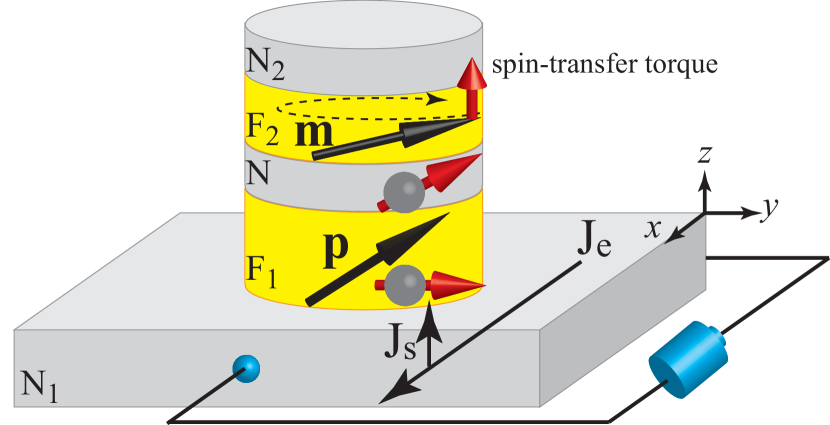
The system we consider is schematically shown in Fig. 1, where two ferromagnets, F1 and F2, are sandwiched by two nonmagnets, N1 and N2. There is another nonmagnet, N, between the F1 and F2 layers. From hereafter, we use the suffixies Fk, Nk, () and N to distinguish quantities related to these layers and their interfaces. The unit vectors pointing in the magnetization direction of the F1 and F2 layers are denoted as and , respectively. The F1 layer acts as the polarizer whereas the F2 layer is the free layer, as described below. An electric current is applied to the N1 layer along -direction. The spin-orbit interaction in the N1 layer scatters the spin-up and spin-down electrons to the opposite directions, generating spin current flowing along -direction and polarizing along -direction. The electric and spin current densities flowing along the - and -directions in the N1 layer are given by [33]
| (1) |
| (2) |
respectively, where is the external electric field in the -direction. The conductivity and the spin Hall angle are and , respectively, where is the resistivity. The spin accumulation is denoted as , whereas is the unit vector in the -direction. We note that the vector notation by boldface represents the direction of the spin polarization. The spin current given by Eq. (2) creates the spin accumulations in each layer, which obey the diffusion equation with the spin diffusion length .
Let us explain the central idea of this paper. The spin polarization of the spin current flowing in the -direction generated in the N1 layer via the spin Hall effect points to the -direction [3,4,33]. However, in the F1 layer, the spin transverse to the local magnetization precesses due to the exchange interaction and relaxes rapidly. As a result, only the spin polarization parallel or antiparallel to direction survives during the transport through the F1 layer. When has a finite -component , the spin current having a finite -component is injected into the F2 layer, and move its magnetization to the -direction, resulting in an excitation of an out-of-plane precession, as schematically shown in Fig. 1. We should emphasize here that the magnetization also has a finite -component because, if , the spin polarization injected from the N1 to F1 layer relaxes at the N1/F1 interface, and the net spin polarization emitted from the F1 to F2 layer becomes zero. Therefore, the magnetization should have both - and -components. In other words, should be tilted in the plane to maximize the efficiency of the spin injection having the finite -component of the spin polarization. This is an important difference from GMR or MTJ, where the -component of the polarizer is unnecessary to excite an out-of-plane auto-oscillation [23-32]. We note that the tilted magnetic anisotropy has been investigated by making use of a higher-order anisotropy or an interlayer exchange coupling between two ferromagnets [34,35].
We show the spin-transfer torque formula acting on the magnetization in the F2 layer. The spin current density at the F2/N interface flowing from the F2 to N layer is given by
| (3) |
where is the sum of the conductances for spin-up and spin-down electrons, and is its spin polarization. The conductance is related to the interface resistance as , where is the cross-sectional area. The real and imaginary parts of the mixing conductance are denoted as and , respectively. Since for typical ferromagnetic/nonmagnetic interfaces [36,37], we neglect the terms related to in the following calculations. The spin currents at the other Fk/Nk and F1/N interfaces are obtained in a similar manner. We assume that the thickness of the N layer is sufficiently thinner than the spin diffusion length, and therefore, the spin current in this layer is conserved. The spin-transfer torque excited in the F2 layer is, according to the conservation law of the angular momentum, the transverse spin current ejected from this layer, i.e., , where , , and are the gyromagnetic ratio, saturation magnetization, and thickness, respectively. Using Eqs. (1)-(3) and the spin diffusion equation, the spin-transfer torque is given by
| (4) |
Here, we define
| (5) |
| (6) |
| (7) |
| (8) |
| (9) |
| (10) |
, respectively. The spin polarization of the conductivity in ferromagnet is . The spin-transfer torque excited in the F1 layer can be calculated in a similar manner [38]. The spin-transfer torques in systems having two ferromagnets with different geometries are discussed in Refs. [39,40]. In the following, we use typical values of the parameters found in experiments and first-principles calculations in the spin Hall geometry; nm, nm nm, nm, , knm2, , , nm-2, nm, nm, rad/(Oe s), and emu/c.c. [14,36,37,41,42].
We study the magnetization dynamics in the F2 layer under the effect of the spin-transfer torque given by Eq. (4). The magnetization in the F1 layer, , is assumed to be pinned. The LLGS equation of the magnetization in the F2 layer is given by
| (11) |
where, according to Eq. (4), and
| (12) |
Using the values of the parameters mentioned above, and . The magnetic field,
| (13) |
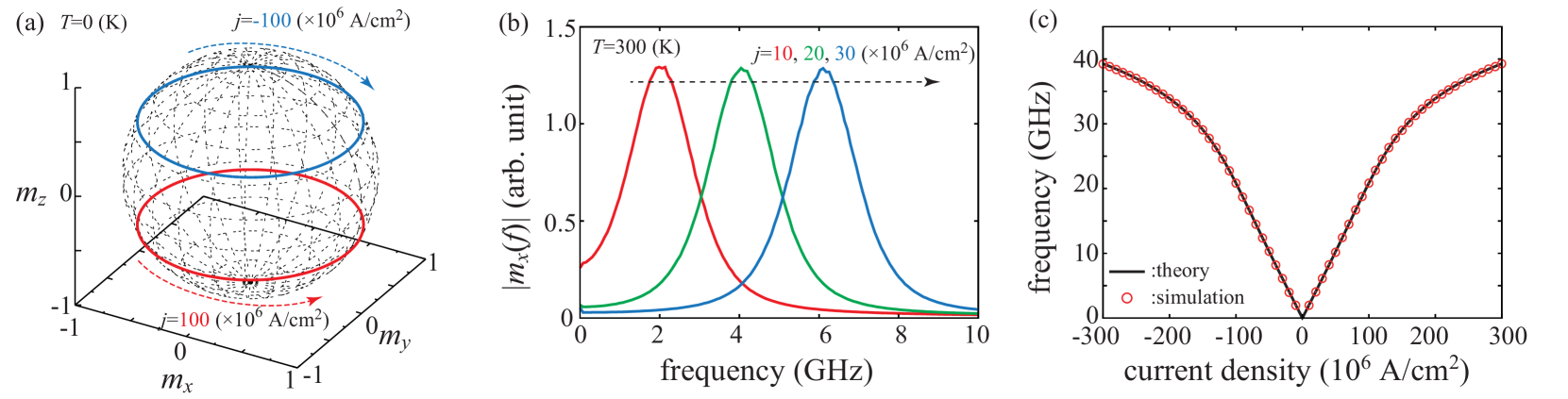
consists of the demagnetization (shape anisotropy) field along the -direction. The Gilbert damping constant is , and we use in this paper. Figure 2(a) shows typical trajectories of the magnetization dynamics in steady states obtained from the numerical simulation of Eq. (11), where A/cm2 and . This figure indicates that the out-of-plane precession can be excited by the spin Hall effect. This is the main result in this paper. We should also emphasize that the oscillation direction, i.e., clockwise or counterclockwise around the -axis, can be changed by changing the sign of . The magnetization moves to the positive (negative) -direction by the negative (positive) current, as shown in Fig. 2(a).
We can obtain the analytical formulas revealing the relation between the current and the oscillation frequency by solving the LLGS equation averaged over the constant energy curve [43]. The energy density in the present system is . An auto-oscillation is excited when the spin-transfer torque compensates with the damping torque, and therefore, the field torque () principally determines the magnetization dynamics. Since the field torque conserves the energy density , the auto-oscillation can be approximated as occuring on a constant energy curve. As a result, we can estimate current density necessary to excite an auto-oscillation on a constant energy curve of from the equation [16], where the time integral is over the precession period. To simplify the discussion we use the cone angle of the magnetization, , instead of , to identify a constant energy curve in the present case. Assuming that lies in the -plane (i.e., and ), the current density necessary to excite the steady precession of the magnetization with the cone angle is found to be
| (14) |
Here, is given by
| (15) |
where and are given by
| (16) |
| (17) |
with and . On the other hand, the precession frequency at the cone angle is
| (18) |
We confirm the validities of Eqs. (14) and (18) by comparing them with the numerical simulations. We add the random torque, , due to thermal fluctuation to Eq. (11), for the sake of generality. The components of the random field satisfy the fluctuation-dissipation theorem, , where the temperature and the volume of the F2 layer are assumed to be K and with nm. We solve Eq. (11) numerically for s with the initial condition . Repeating such calculation times with random , the averaged Fourier spectra of the -component of , , are obtained, as shown in Fig. 2(b). As shown, each spectrum have one peak at a certain frequency, which increases with increasing the current magnitude. The dependence of the peak frequency on the current obtained from such simulation is shown by red circles in Fig. 2(c). The analytical relation between the current and frequency obtained from Eqs. (14) and (18) is also shown in Fig. 2(c) by the black (solid) line. We obtain good agreement between the simulation and analytical formulas, indicating the validity of Eqs. (14) and (18).
In this paper, we consider an excitation of an auto-oscillation in an in-plane magnetized free layer by inserting an additional ferromagnet between the free layer and the nonmagnet having the spin Hall effect. We also notice that another situation is possible [43], where an auto-oscillation of a perpendicularly magnetized free layer is excited by adding another ferromagnet on the other side of the nonmagnet.
III Application to microwave assisted magnetization reversal
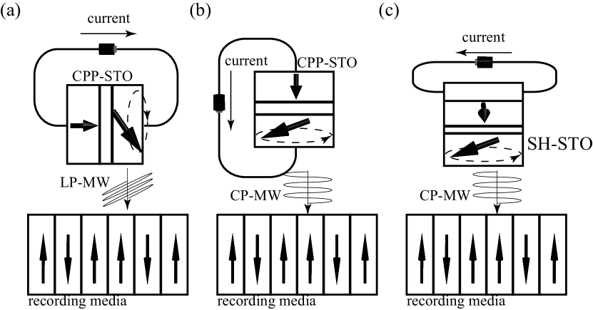
At the end of this paper, let us discuss the application of the above result to magnetic recording. A spin torque oscillator (STO) consisting of an in-plane magnetized free layer and a perpendicularly magnetized pinned layer [23-26] is a candidate for the recording head of a hard disk drive using MAMR [28-32,45]. An oscillating magnetic field generated from the STO acts as a microwave field on the recording bit, and reduces the recording field [45]. In the original design of MAMR, an STO having a current-perpendicular-to-plane (CPP) structure was assumed [45], where the current flows parallel to the recording media, as shown in Fig. 3(a). In this case, only a linearly poralized field with regard to the recording bit can be obtained in the microwave field emitted from the STO.
This design, however, does not make full use of the idea embodied in MAMR. An interesting idea in MAMR is the chirality matching between the STO and the recording bit. As shown in Fig. 2(a), the magnetization in an STO consisting of in-plane magnetized free layer shows oscillation with both clockwise and counterclockwise chiralities, depending on the sign of the current. The magnetization in the recording bit also has an oscillation chirality, depending on the magnetized direction. It was shown that the recording field in MAMR is significantly reduced when the chirality of the STO matches with that of the recording bit [44]. According to this principle of the chirality matching, Kudo et al. proposed a concept of resonant switching [30,46], where the current in the STO flows along the direction perpendicular to the recording media; see Fig. 3(b). In this case, the microwave field emitted from the STO is a circularly polarized with regard to the recording bit. Therefore, by changing the current direction in the STO, the oscillating field having the chirality of both the clockwise and counterclockwise can be generated, and applied in MAMR by taking considerations of chirality matching into account.
The results shown in this paper may add another vital advantage in designing the recording head in MAMR. For example, let us consider the system shown in Fig. 3(c), where the current in the recording head flows parallel to the recording media. In this structure, the current does not flow in the free layer, in contrast to the structure shown in Fig. 3(a). Instead, the spin Hall effect excites an oscillation in the free layer, as schematically shown in Fig. 1. The circularly polarized microwave field is then emitted from the STO, as in the case shown in Fig. 3(b). Therefore, the structure in Fig. 3(c) satisfies the condition to achieve MAMR combined with chirality matching. In addition, the vital advantage, which resides in this structure, is that the recording head can in principle be placed closer to the media than in the case of Fig. 3(b) because of the absence of the electrode between the free layer and the recording media. Therefore, the STO using the spin Hall effect will be an interesting candidate for the recording head of next generation.
IV Conclusion
In conclusion, it was shown that the spin Hall effect can excite the out-of-plane precession of the magnetization in a ferromagnet by inserting another ferromagnet having a tilted magnetization between the nonmagnetic heavy metal and the ferromagnet. The phenomenon is due to the relaxation of the transverse spin in this additional ferromagnet. Although the relaxation of the spin in the additional layer induces a loss of spin polarization, it enables us to manipulate the direction of the spin-transfer torque excited on the free layer. Using the spin-transfer torque formula derived from the diffusive spin-transport theory and solving the LLGS equation both numerically and analytically, the relation between the current and the precession frequency was obtained. It was also shown that the chirality of the precession can be reversed by reversing the current direction. An application to magnetic recording using microwave assisted magnetization reversal was also discussed.
Note added: After our submission, we were notified that Dr. Suto in Toshiba proposed another solution based on a nonlocal injection of spin current to generate a circularly polarized microwave from a spin-valve with a current flowing parallel to the recording media (unpublished).
Acknowledgment
The author is grateful to Takehiko Yorozu, Yoichi Shiota, Hitoshi Kubota, and Shingo Tamaru for valuable discussions. The author is also thankful to Satoshi Iba, Aurelie Spiesser, Hiroki Maehara, and Ai Emura for their support and encouragement. This work was supported by JSPS KAKENHI Grant-in-Aid for Young Scientists (B) 16K17486.
References
- [1] J. C. Slonczewski, ”Current-driven excitation of magnetic multilayers”, J. Magn. Magn. Mater. vol. 159, p.L1, 1996.
- [2] L. Berger, ”Emission of spin waves by a magnetic multilayer traversed by a current”, Phys. Rev. B vol. 54, 9353, 1996.
- [3] M. I. Dyakonov and V. I. Perel, ”Current-induced spin orientation of electrons in semiconductors”, Phys. Lett. A vol. 35, 459, 1971.
- [4] J. E. Hirsch, ”Spin Hall Effect”, Phys. Rev. Lett. vol. 83, 1834, 1999.
- [5] L. Liu, O. J. Lee, T. J. Gudmundsen, D. C. Ralph, and R. A. Buhrman, ”Current-Induced Switching of Perpendicularly Magnetized Magnetic Layers Using Spin Torque from the Spin Hall Effect”, Phys. Rev. Lett. vol. 109, 096602, 2012.
- [6] C.-F. Pai, L. Liu, Y. Li, H. W. Tseng, D. C. Ralph, and R. A. Buhrman, ”Spin transfer torque devices utilizing the giant spin Hall effect of tungsten”, Appl. Phys. Lett. vol. 101, 122404, 2012.
- [7] K.-W. Kim, S.-M. Seo, J. Ryu, K.-J. Lee, and H.-W. Lee, ”Magnetization dynamics induced by in-plane currents in ultrathin magnetic nanostructures with Rashba spin-orbit coupling”, Phys. Rev. B vol. 85, 180404, 2012.
- [8] K. Garello, I. M. Miron, C. O. Avci, F. Freimuth, Y. Mokrousov, S. Blügel, S. Auffret, O. Boulle, G. Gaudin, and P. Gambardella, ”Symmetry and magnitude of spin-orbit torques in ferromagnetic heterostructures”, Nat. Nanotechnol. vol. 8, 587, 2013.
- [9] J. Kim, J. Sinha, M. Hayashi, M. Yamanouchi, S. Fukami, T. Suzuki, S. Mitani, and H. Ohno, ”Layer thickness dependence of the current-induced effective field vector in Ta/CoFeB/MgO”, Nat. Mater. vol. 12, 240, 2013.
- [10] X. Fan, J. Wu, Y. Chen, M. J. Jerry, H. Zhang, and J. Q. Xiao, Nat. Commun. 4, 1799 (2013). ”Observation of the nonlocal spin-orbital effective field”, Nat. Commun. vol. 4, 1799, 2013.
- [11] X. Qiu, P. Deorani, K. Narayanapillai, K.-S. Lee, K.-J. Lee, H.-W. Lee, and H. Yang, Sci. Rep. 4, 4491 (2014). ”Angular and temperature dependence of current induced spin-orbit effective fields in Ta/CoFeB/MgO nanowires”, Sci. Rep. vol. 4, 4491, 2014.
- [12] G. Yu, P. Upadhyaya, Y. Fan, J. Alzate, W. Jiang, K. L. Wong, S. Takei, S. A. Bender, L.-T. Chang, Y. Jiang, M. Lang, J. Tang, Y. Wang, Y. Tserkovnyak, P. K. Amiri, and K. L. Wang, ”Switching of perpendicular magnetization by spin-orbit torques in the absence of external magnetic fields”, Nat. Nanotechnol. vol. 9, 548, 2014.
- [13] M. Cubukcu, O. Boulle, M. Drouard, K. Garello, C. O. Avci, I. M. Miron, J. Langer, B. Ocker, P. Gambardella, and G. Gaudin, Appl. Phys. Lett. 104, 042406 (2014). ”Spin-orbit torque magnetization switching of a three-terminal perpendicular magnetic tunnel junction”, Appl. Phys. Lett. vol. 104, 042406, 2014.
- [14] J. Torrejon, F. Garcia-Sanchez, T. Taniguchi, J. Shinha, S. Mitani, J.-V. Kim, and M. Hayashi, ”Current-driven asymmetric magnetization switching in perpendicularly magnetized CoFeB/MgO heterostructures”, Phys. Rev. B vol. 91, 214434, 2015.
- [15] K. Kudo and T. Morie, ”Self-feedback electrically coupled spin-Hall oscillator array for pattern-matching operation”, Appl. Phys. Express vol. 10, 043001, 2017.
- [16] T. Taniguchi, ”Nonlinear analysis of magnetization dynamics excited by spin Hall effect”, Phys. Rev. B vol. 91, 104406, 2015.
- [17] J. A. Katine, F. J. Albert, R. A. Buhrman, E. B. Myers, and D. C. Ralph, ”Current-Driven Magnetization Reversal and Spin-Wave Excitations in Co/Cu/Co Pillars”, Phys. Rev. Lett. vol. 84, 3149, 2000.
- [18] J. Grollier, V. Cros, A. H. J. M. George, H. Jaffrës, and A. Fert, Appl. Phys. Lett. 78, 3663 (2001). ”Spin-polarized current induced switching in Co/Cu/Co pillars”, Appl. Phys. Lett. vol. 78, 3663, 2001.
- [19] S. I. Kiselev, J. C. Sankey, I. N. Krivorotov, N. C. Emley, R. J. Schoelkopf, R. A. Buhrman, and D. C. Ralph, ”Microwave oscillations of a nanomagnet driven by a spin-polarized current”, Nature vol. 425, 380, 2003.
- [20] W. H. Rippard, M. R. Pufall, S. Kaka, T. J. Silva, and S. E. Russek, ”Current-driven microwave dynamics in magnetic point contacts as a function of applied field angle”, Phys. Rev. B vol. 70, 100406, 2004.
- [21] H. Kubota, A. Fukushima, Y. Ootani, S. Yuasa, K. Ando, H. Maehara, K. Tsunekawa, D. D. Djayaprawira, N. Watanabe, and Y. Suzuki, ”Evaluation of Spin-Transfer Switching in CoFeB/MgO/CoFeB Magnetic Tunnel Junctions”, Jpn. J. Appl Phys. vol. 44, L1237, 2005.
- [22] I. N. Krivorotov, N. C. Emley, J. C. Sankey, S. I. Kiselev, D. C. Ralph, and R. A. Buhrman, ”Time-Domain Measurements of Nanomagnet Dynamics Driven by Spin-Transfer Torques”, Science vol. 307, 228, 2005.
- [23] A. D. Kent, B. Özyilmaz, and E. del Barco, ”Spin-transfer-induced precessional magnetization reversal”, Appl. Phys. Lett. vol. 84, 3894, 2004.
- [24] K. J. Lee, O. Redon, and B. Dieny, ”Analytical investigation of spin-transfer dynamics using a perpendicular-to-plane polarizer”, Appl. Phys. Lett. vol. 86, 022505, 2005.
- [25] D. Houssameddine, U. Ebels, B. Delaët, B. Rodmacq, I. Firastrau, F. Ponthenier, M. Brunet, C. Thirion, J.-P. Michel, L. Prejbenu-Buda, M.-C. Cyrille, O. Redon and B. Dieny, ”Spin-torque oscillator using a perpendicular polarizer and a planar free layer”, Nat. Matter. vol. 6, 447, 2007.
- [26] U. Ebels, D. Houssameddine, I. Firastrau, D. Gusakova, C. Thirion, B. Dieny, and L. D. Buda-Prejbeanu, ”Macrospin description of the perpendicular polarizer-planar free-layer spin-torque oscillator”, Phys. Rev. B vol. 78, 024436, 2008.
- [27] Y. Zhou, C. L. Zha, S. Bonetti, J. Persson, and J. Akerman, ”Spin-torque oscillator with tilted fixed layer magnetization”, Appl. Phys. Lett. vol. 92, 262508, 2008.
- [28] H. Suto, T. Yang, T. Nagasawa, K. Kudo, K. Mizushima, and R. Sato, ”Magnetization dynamics of a MgO-based spin-torque oscillator with a perpendicular polarizer layer and a planar free layer”, J. Appl. Phys. vol. 112, 083907, 2012.
- [29] H. Suto, T. Nagasawa, K. Kudo, K. Mizushima, and R. Sato, ”Nanoscale layer-selective readout of magnetization direction from a magnetic multilayer using a spin-torque oscillator”, Nanotechnology vol. 25, 245501, 2014.
- [30] K. Kudo, H. Suto, T. Nagasawa, K. Mizushima, and R. Sato, ”Frequency stabilization of spin-torque-driven oscillations by coupling with a magnetic nonlinear resonator”, J. Appl. Phys. vol. 116, 163911, 2014.
- [31] T. Taniguchi and H. Kubota, ”Instability analysis of spin-torque oscillator with an in-plane magnetized free layer and a perpendicularly magnetized pinned layer”, Phys. Rev. B vol. 93, 174401, 2016.
- [32] T. Taniguchi, ”Crossover between fast and slow excitation of magnetization by spin torque”, Appl. Phys. Express vol. 9, 073003, 2016.
- [33] S. Takahashi and S. Maekawa, ”Spin Current in Metals and Superconductors”, J. Phys. Soc. Jpn. vol. 77, 031009, 2008.
- [34] J.-W. Lee, J.-R. Jeong, S.-C. Shin, J. Kim, and S.-K. Kim, ”Spin-reorientation transitions in ultrathin Co films on Pt(111) and Pd(111) single-crystal substrates”, Phys. Rev. B vol. 66, 172409, 2002.
- [35] L. Fallarino, V. Sluka, B. Kardasz, M. Pinarbasi, A. Berger, and A. D. Kent, ”Interlayer exchange coupling between layers with perpendicular and easy-plane magnetic anisotropies”, Appl. Phys. Lett. vol. 109, 082401, 2016.
- [36] A. Brataas, Y. V. Nazarov, and G. E. W. Bauer, ”Spin-transport in multi-terminal normal metal-ferromagnet systems with non-collinear magnetizations”, Eur. Phys. J. B vol. 22, 99, 2001.
- [37] M. Zwierzycki, Y. Tserkovnyak, P. J. Kelly, A. Brataas, and G. E. W. Bauer, ”First-principles study of magnetization relaxation enhancement and spin transfer in thin magnetic films”, Phys. Rev. B vol. 71, 064420, 2005.
- [38] T. Taniguchi, S. Mitani, and M. Hayashi, ”Current-Induced Instability of a Perpendicular Ferromagnet in Spin Hall Geometry”, IEEE Trans. Magn. vol. 52, 1400204, 2016.
- [39] W. T. Chen, S. Takahashi, H. Nakayama, M. Althammer, S. T. B. Goennewein, E. Saitoh, and G. E. W. Bauer, ”Theory of spin Hall magnetoresistance”, Phys. Rev. B vol. 87, 144411, 2013.
- [40] T. Taniguchi, J. Grollier, and M. D. Stiles, ”Spin-Transfer Torques Generated by the Anomalous Hall Effect and Anisotropic Magnetoresistance”, Phys. Rev. Applied vol. 3, 044001, 2015.
- [41] J. Bass and J. W. P. Pratt, ”Spin-diffusion lengths in metals and alloys, and spin-flipping at metal/metal interfaces: an experimentalist fs critical review”, J. Phys.: Condens. Matter. vol. 19, 183201, 2007.
- [42] T. Taniguchi, S. Yakata, H. Imamura, and Y. Ando, ”Determination of Penetration Depth of Transverse Spin Current in Ferromagnetic Metals by Spin Pumping”, Appl. Phys. Express vol. 1, 031302, 2008.
- [43] G. Bertotti, I. Mayergoyz, and C. Serpico, ”Nonlinear magnetization Dynamics in Nanosystems” (Elsevier, Oxford, 2009).
- [44] T. Taniguchi, ”Indirect excitation of self-oscillation in perpendicular ferromagnet by spin Hall effect”, Appl. Phys. Lett. vol. 111, 022410, 2017.
- [45] J.-G. Zhu, X. Zhu, and Y. Tang, ”Microwave Assisted Magnetic Recording”, IEEE Trans. Magn. vol. 44, 125, 2008.
- [46] K. Kudo, H. Suto, T. Nagasawa, K. Mizushima, and R. Sato, ”Resonant magnetization switching induced by spin-torque-driven oscillations and its use in three-dimensional magnetic storage applications Appl. Phys. Express vol. 8, 103001, 2015.