A lattice Boltzmann method for thin liquid film hydrodynamics
Abstract
We propose a novel approach to the numerical simulation of thin film flows, based on the lattice Boltzmann method. We outline the basic features of the method, show in which limits the expected thin film equations are recovered and perform validation tests. The numerical scheme is applied to the viscous Rayleigh-Taylor instability of a thin film and to the spreading of a sessile drop towards its equilibrium contact angle configuration. We show that the Cox-Voinov law is satisfied, and that the effect of a tunable slip length on the substrate is correctly captured. We address, then, the problem of a droplet sliding on an inclined plane, finding that the Capillary number scales linearly with the Bond number, in agreement with experimental results. At last, we demonstrate the ability of the method to handle heterogenous and complex systems by showcasing the controlled dewetting of a thin film on a chemically structured substrate.
I Introduction
Thin layers of liquids on solid surfaces are frequently encountered in a host of natural and technological settings de Gennes et al. (2003); Focke et al. (2010). Therefore, understanding and controlling their stability and dynamics is a central problem for fundamental physics, as well as for applied research in process engineering and nanotechnology Oron et al. (1997); Utada et al. (2007). Coating processes, for instance, rely crucially on the mutual affinity of liquid and surface (i.e. on wettability properties). When the liquid film is sufficiently thin, in fact, it can become unstable, leading to the dewetting of the coated area Bonn et al. (2009). From the modelling point of view, the challenge consists in the fact that the physics of thin films is intrinsically multiscale, for it involves phenomena ranging from the molecular scale at the three phase contact line, to the micro-/nano-metric size of the film thickness, to the size of the film as a whole, extending over the coated substrate area.
A fully resolved bottom-up atomistic approach would be, obviously, unfeasible, if hydrodynamic regimes are to be explored. It clearly appears that some degree of model order reduction is required. Most hydrodynamic models of thin liquid films, in the framework of the lubrication theory, simplify the complexity of the full 3D Navier-Stokes equations Navier (1823); Stokes (1842) to one scalar transport equation (the lubrication equation) for the film thickness field Reynolds (1886); Oron et al. (1997); Craster and Matar (2009); Mitlin (1993):
| (1) |
Here, is the mobility function, whose explicit form depends on the boundary condition for the velocity at the surface (for a no-slip boundary, , with being the dynamic viscosity), and is the film pressure at the free liquid surface. Stable and reliable direct numerical simulations of Eq. (1) require sophisticated numerical methods, whose execution is often computationally expensive Becker et al. (2003). Moreover, an ever-growing number of microfluidic problems requires to cope with complex fluids rather than simple liquids, i.e. fluids with non-trivial internal microstructure and/or complex non-Newtonian rheological behaviour (e.g. colloidal suspensions, polymer solutions, etc.). The quest for an efficient multiscale numerical method for simulating thin film hydrodynamics, versatile for the inclusion of multiphysics features, is, thus, an ongoing endeavour.
In this paper, we present a novel approach to the numerical study of thin liquid films, based on the lattice Boltzmann method (LBM) Succi (2001). Due to the built-in properties of the LBM, our method enjoys an outstanding computational performance, especially on parallel architectures and graphics processing units.
The paper is organized as follows. We first present the numerical model and discuss the equations of motion for the hydrodynamic fields that the model covers. We then show that these equations effectively correspond, under certain limits, to the lubrication equation of Reynolds. In section III we present validation results including the Rayleigh-Taylor instability of thin fluid films, the spreading of a sessile droplet on a substrate and the sliding of a droplet on an inclined plane. After showcasing the ability of our method to handle large and heterogeneous substrates, we present some computational aspects including the performance of our implementation for Graphics Processing Units (GPUs). An appendix is added to provide numerical tests of the validity of the correspondence with lubrication theory (appendix A).
II Numerical model
When a layer of fluid is characterized by a vertical length scale much smaller than the longitudinal one , the equations of motion can be simplified under the approximation that the ratio of the length scales, , is small (, see Fig. 1).
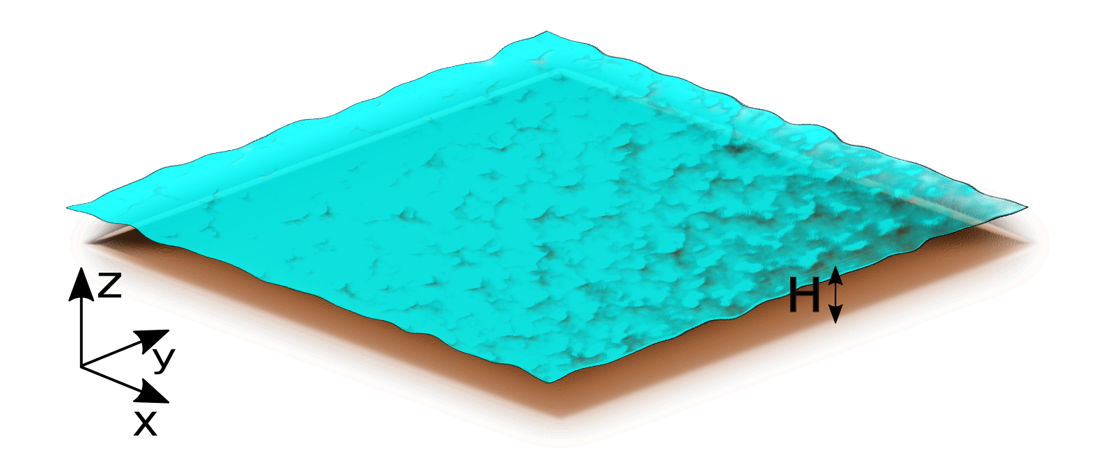
In this limit, and for small reduced Reynolds number, (where , with being a characteristic velocity of the fluid system and being the fluid’s kinematic viscosity), the lubrication approximation tells that the dynamics is governed by equation (1). Instead of directly solving Eq. (1) numerically, we follow an alternative strategy. We build our numerical model on a class of LBMs originally proposed as solvers for the shallow water equations Salmon (1999); Dellar (2002); Zhou (2004); Van Thang et al. (2010). The lattice Boltzmann equation for the discrete probability density functions of a fluid system subject to a total force (that can include both internal and external forces) , , reads:
| (2) |
where labels the lattice velocities and runs from to , with being the number of velocities characterizing the scheme. Algorithmically, this equation can be seen as made up of two steps. A local collision step where the “relax” towards the local equilibrium distributions with rate (where , the relaxation time, is proportional to the kinematic viscosity ): the distribution functions are substituted by their weighted average (with weights and ) with the equilibria, with an added so-called ”source” term (the last term on the right hand side of Eq. (2)), when a force is present. A non-local streaming step where the updated distribution functions are scattered to the nearest neighbouring sites. The parameters (the lattice speed of sound) and (the so called ”weights”) depend on the geometry of the lattice and are determined under suitable constraints on the form of the tensorial moments in the lattice velocities up to fourth order Wolf-Gladrow (2001). We work with two-dimensional square lattices of side length , with lattice constant and . For simplicity, we keep throughout this paper and follow the standard notation, where and the , , are Qian et al. (1992); Shan et al. (2006)
| (3) |
with the corresponding weights
| (4) |
The equilibrium distribution functions have to be determined to recover the desired equations of motion for hydrodynamic fields in the long wavelength limit (we will return to this shortly). They have, therefore, to fulfill the following relations involving the liquid height
| (5) |
momentum
| (6) |
and momentum flux tensor field
| (7) |
where the left hand side coincides with the momentum flux of the shallow water equation, with the term being the hydrostatic pressure in a thin fluid layer at rest Dellar (2002). With the usual ansatz of a quadratic polynomial in the velocity field , the equilibrium distribution functions read
| (8) |
where is the magnitude of the velocity. The multiscale Chapman-Enskog expansion Chapman and Cowling (1939); Enskog (1917) of such a LBM yields (for small ratios of the Mach, , and Froude, , numbers, corresponding also to ) the following equations for the height and velocity fields Dellar (2002); Van Thang et al. (2010); Salmon (1999)
| (9) |
where , the kinematic viscosity, is related to the relaxation rate appearing in (2) via . For stability of the scheme, the condition is also required, which is fulfilled in all our applications, given the low values of (as discussed in more detail later on). Different terms contribute to the total (generalized) force111The generalized forces have indeed the dimensions of . :
| (10) |
In the first term the film pressure appearing in (1) is included as , where the film pressure is written as
| (11) |
and is the (constant) liquid density (equal to , in LBM units). The first term in Eq. (11) represents the capillary Laplace pressure (with being the surface tension) while the second term is the disjoining pressure, Various forms have been proposed for in the literature Oron et al. (1997); Thiele (2014), where here we use the expression
| (12) | |||||
In Eq. (12), is the contact angle and corresponds to the precursor film thickness. The integers and are set to be and , respectively. These are commonly chosen values in the literature Moulton and Lega (2013); Oron et al. (1997) that correspond to a standard Lennard-Jones intermolecular potential Fischer and Grün (2018), though other pairs can be used (e.g. Diez et al. (2009); Wilczek et al. (2017); Wedershoven et al. (2014)). By adjusting we are thus able to address the wetting properties of the substrate. The film pressure is specific to model thin film dynamics, in general however one can make use of other force terms e.g. to couple fluid layers which has been shown in Rocca et al. (2012). The second term on the right hand side in Eq. (10) introduces a friction with the substrate of the form
| (13) |
with the coefficient given by
| (14) |
Here, acts as a regularizing parameter, which can be identified with an effective slip length. Finally, the last term in Eq. (10), accounts for any other possible source of forcing (e.g. the gravity component parallel to the substrate in the case of a liquid film deposited on an inclined plate). Equipped with such extra terms, equations (9) become
| (15) |
Let us notice at this point that for most microfluidic applications we are actually interested in, the advection term on the left hand side of the second equation of (15) is indeed negligible as compared to the right hand side (the Reynolds number Reynolds (1883); Sommerfeld (1908) being much smaller than one). Analogously, the longitudinal viscous terms and are of order smaller in the ratio of length scales than the friction term (since the former scale as , whereas the latter as ). Therefore they can also be neglected. The validity of these considerations has been numerically tested in some selected cases (representative of typical applications) and the results are shown and discussed in the appendix. Equations (15) reduce then to
| (16) |
For processes evolving on time-scales such that , one can consider the “quasi-steady” limit of the second of these equations (setting ), which yields
| (17) |
effectively enslaving the dynamics of to that of . In the no slip limit, , and in absence of gravity and other forces, Eq. (17) simplifies into
with the dynamic viscosity . Inserting this result into the first equation of (16) leads to
which is precisely the lubrication equation. In essence, our method is, therefore, an alternative solver of the lubrication equation (at least in the inertialess regime, , and for very thin films, ), that brings in, from the computational point of view, the added values of excellent scalability of the corresponding LBM algorithm on parallel architectures, as we shall see in the following sections. Similar ideas have also been developed for reaction-diffusion equations Calì et al. (1992); Kingdon and Schofield (1992); Chen et al. (1995); Weimar and Boon (1996) and the modelling of surface tension effects by gradients of auxiliary fields Swift et al. (1996); Lishchuk et al. (2003) based on the color gradient method Gunstensen et al. (1991).
Before concluding this section, let us notice that special care has to be taken in the implementation of the numerical scheme, when evaluating the forcing term since it contains higher order derivatives (the gradient , which in turn includes the Laplace pressure , see Eq.( 11) and, hence, spurious lattice effects may arise. We noticed, for example, that a centered scheme to calculate gradients Zhou (2004) does not guarantee the sufficient degree of isotropy on the lattice as, e.g., for the relaxation of a droplet (discussed in section III), where it led to unphysical droplet shapes. Therefore, we use the following expressions to compute the gradients
| (18) |
and the Laplacian
| (19) |
respectively Junk and Klar (2000); Thampi et al. (2013), for a generic scalar field (be it the height field , the pressure or a position dependent surface tension field). Besides the higher degree of the isotropy, the scheme (18-II) has the advantage of employing directly the set of lattice Boltzmann speeds.
III Results
Below we present results from numerical simulations using the method introduced in the previous section. For all simulations, we apply periodic boundary conditions in the - plane.
III.1 The Rayleigh-Taylor instability
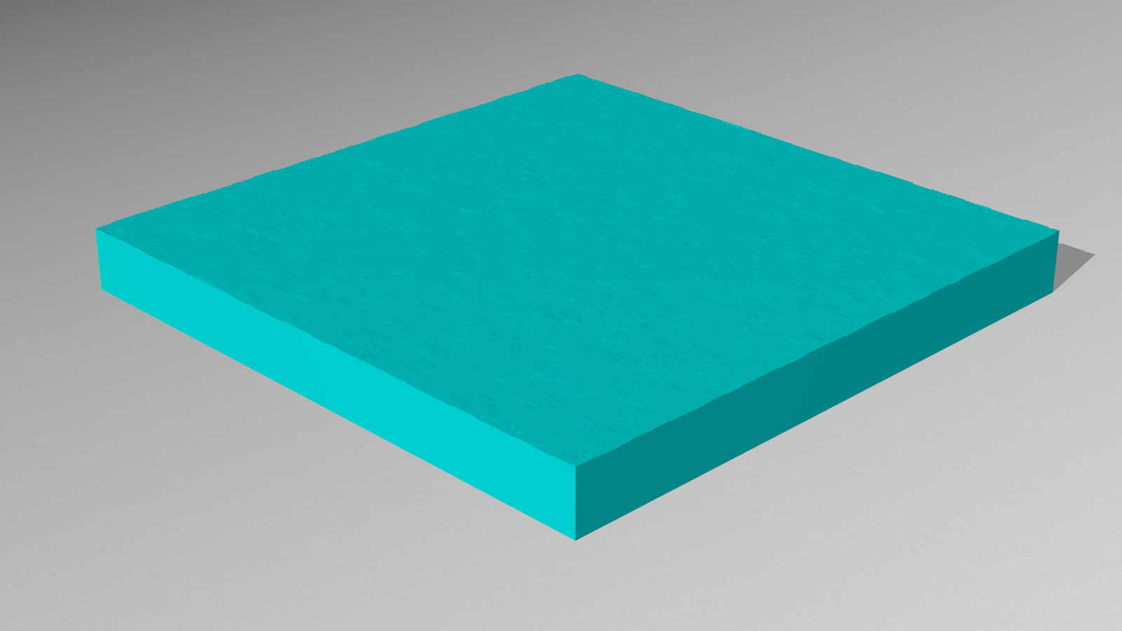
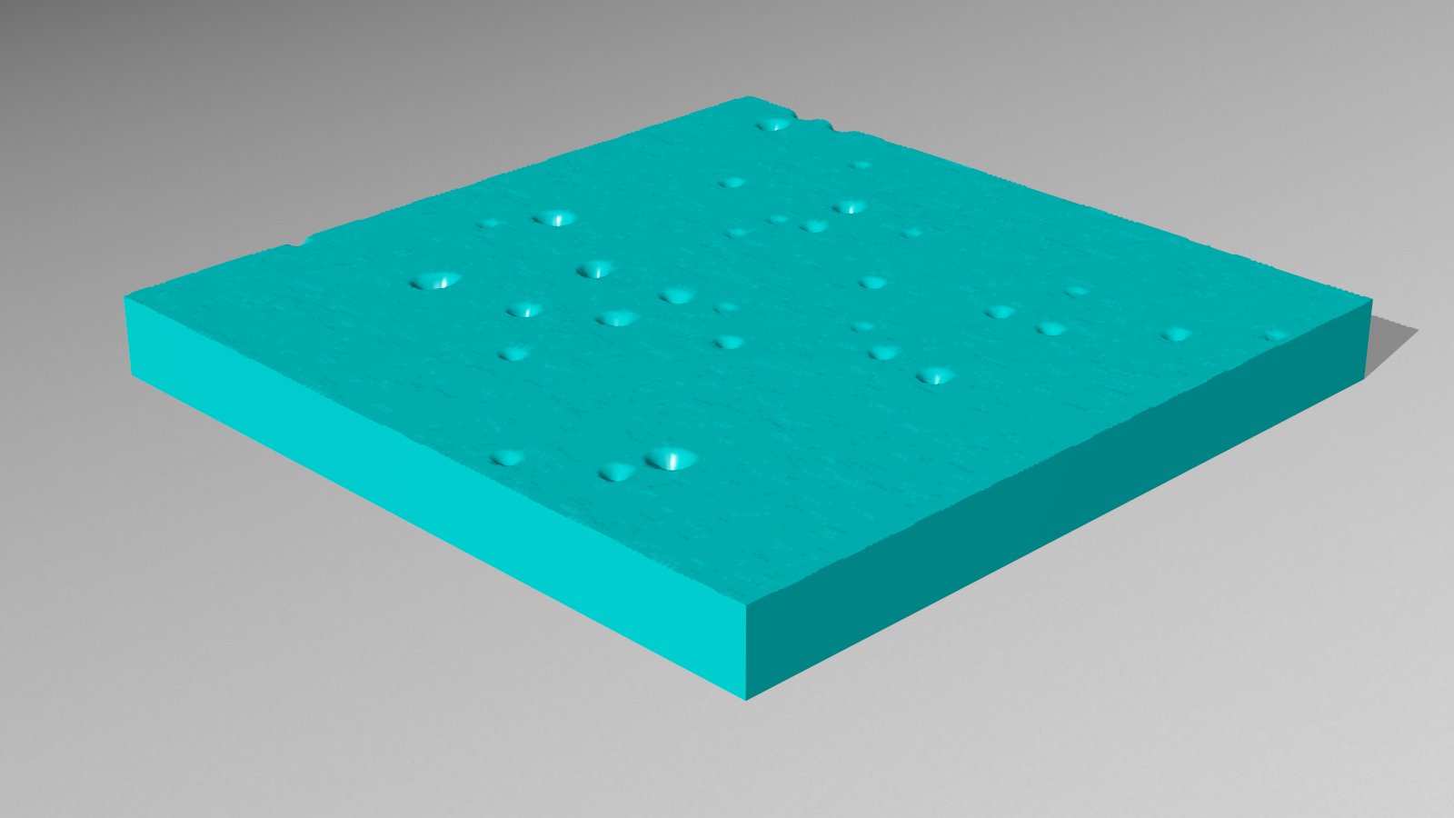
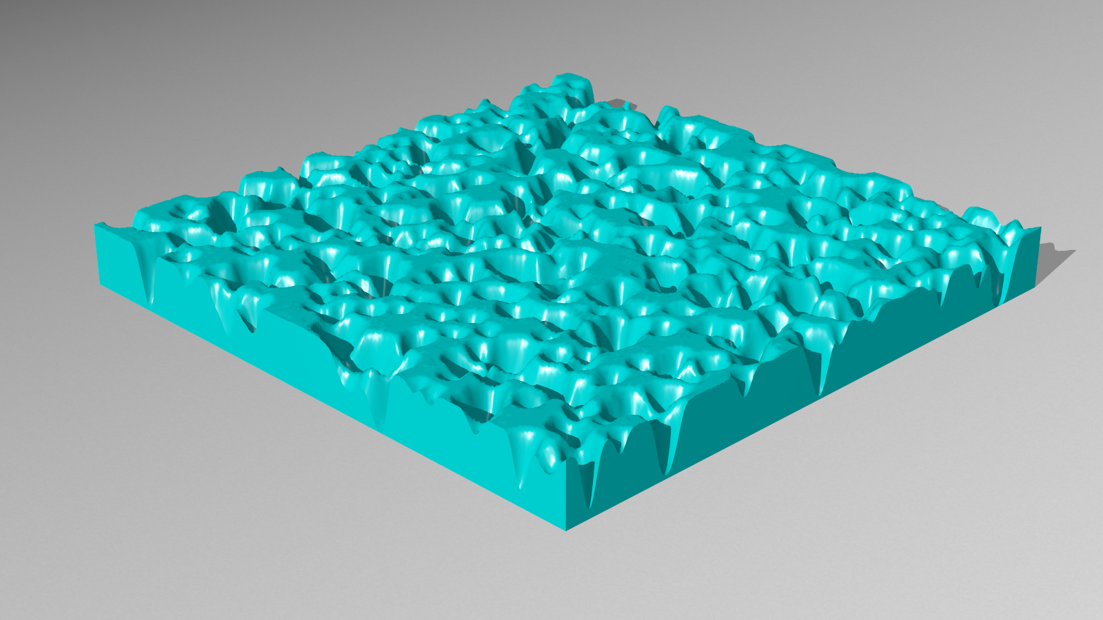
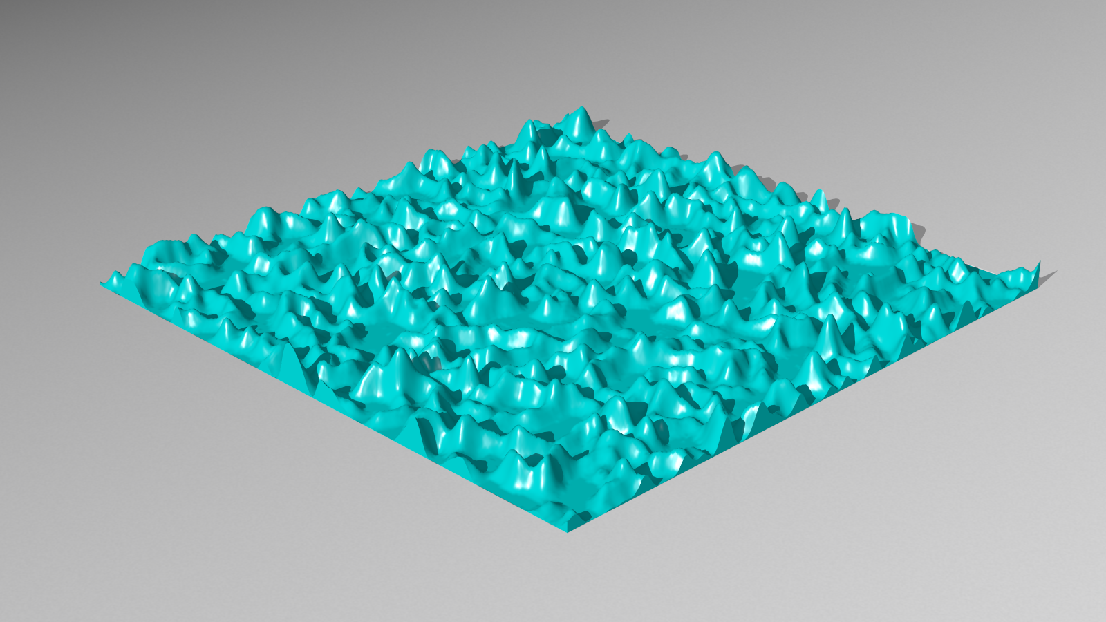
The Rayleigh-Taylor instability occurs when a denser fluid is accelerated against a less dense one Rayleigh (1900); Taylor (1950); Kull (1991); Sharp (1984). This can be the case, for instance, for a liquid film coating a ceiling, under the action of gravity. In such a configuration gravity tends, of course, to deform (and eventually disrupt) the film, while surface tension has a stabilizing effect. As a result of these competing mechanisms, any surface perturbation is stable or unstable depending on whether its characteristic wavenumber is smaller or larger than a certain critical value . Linear stability analysis calculations in the framework of lubrication theory provide the following growth rate :
| (20) |
where is the capillary length. Unstable (stable) modes correspond to () and the critical wavenumber is, therefore, such that , i.e. . On a lattice of size nodes, we initialize the film height according to
| (21) |
with a random variable homogeneously distributed in and . Forcing should always be below a certain threshold. Thus, for the gravitational acceleration we choose values within the interval . Furthermore, we fix the surface tension to be . This results in critical wavenumbers ranging from to . Fig. 2 shows snapshots of the free surface from various time steps, where the growth of the perturbations is shown as time increases. The last panel is already beyond the linear regime.
We consider the time evolution of the power spectrum of the height field fluctuations (around the mean), defined as
| (22) |
where
| (23) |
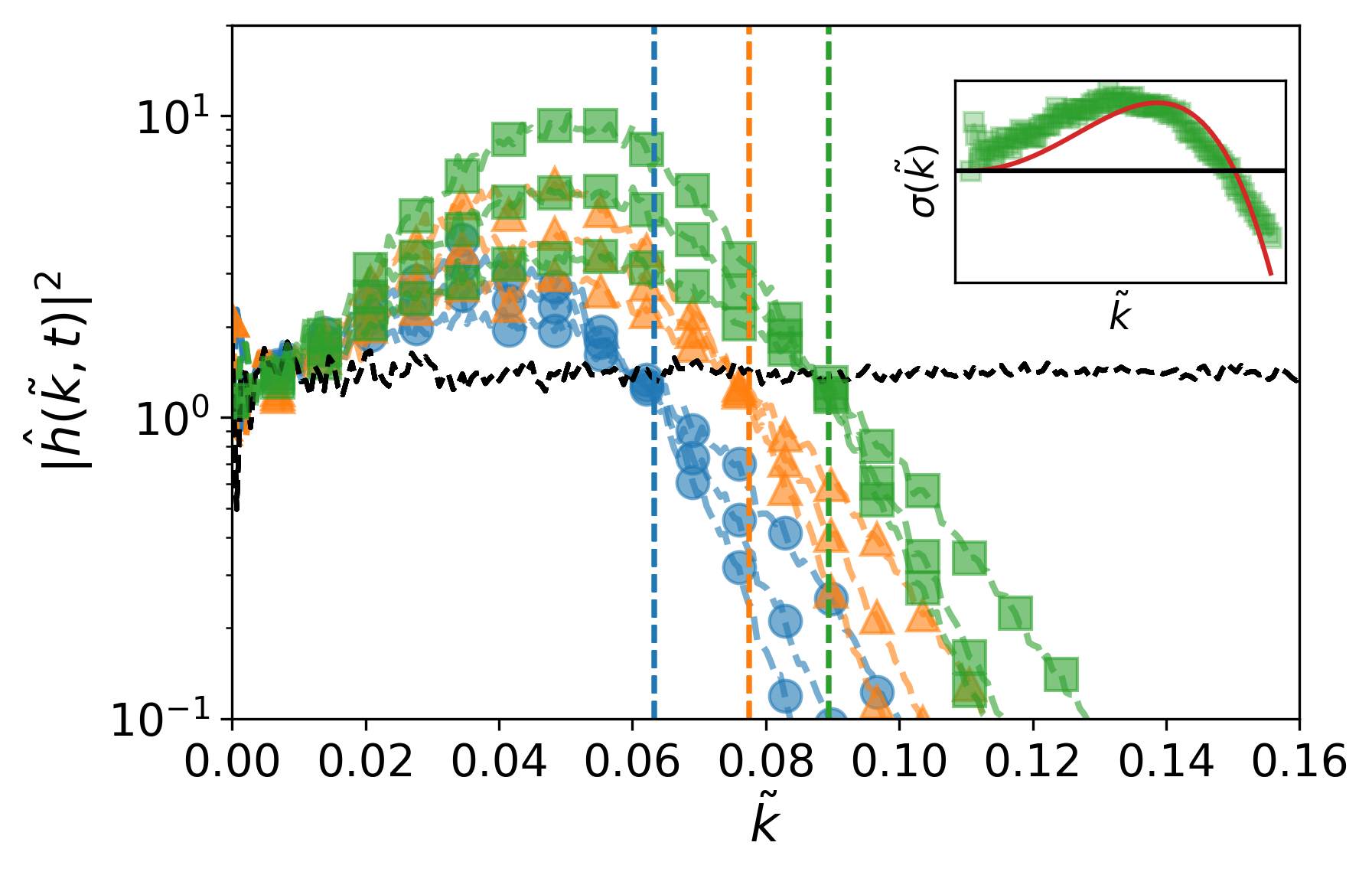
with . denotes the circle in -space (i.e. ). Since we work in a discretized system we have to smear out the circle with some small . Therefore, strictly speaking the integral is not computed around the circle but around some small annulus . The spectra are shown in Fig. 3. The various colors and symbols of Fig. 3 relate to different values of gravitational acceleration. For every set we consider the spectra at three equally scaled times , where
| (24) |
. The values of correspond to the points where the colored lines with symbols cut the black dashed line. The horizontal colored dashed lines mark the theoretical values for . We observe good agreement of theoretical and numerical values. In the inset of Fig. 3 we plot the growth rate for the data of together with the theoretical expression given by Eq. (20) (solid line).
Consistently with the random initialization, at the spectrum is a constant (black dashed line). For , develops a profile that grows in time for , while it is damped out for , in agreement with the expectation from the theory.
III.2 A spreading droplet
Let us consider the problem of a droplet, deposited on a smooth substrate with an apparent contact angle , which spreads to relax to a shape dictated by the equilibrium contact angle . The equilibrium contact angle quantifies the wettability of a given substrate by a certain liquid and can be calculated using Young’s equation de Gennes (1985)
| (25) |
with and being the surface tensions between solid/liquid and solid/gas, respectively.
In our simulations we set the equilibrium contact angle through the disjoining pressure (Eq. (12)). In order to comply as much as possible with the thin film assumptions, we limit ourselves to relatively small contact angles.
To probe the spreading, on a lattice we initialize a droplet, whose surface is given by the expression
| (26) |
with () being the radius of the droplet with a spherical cap shape, and its center. The droplet is placed in the center of the lattice, i.e. .
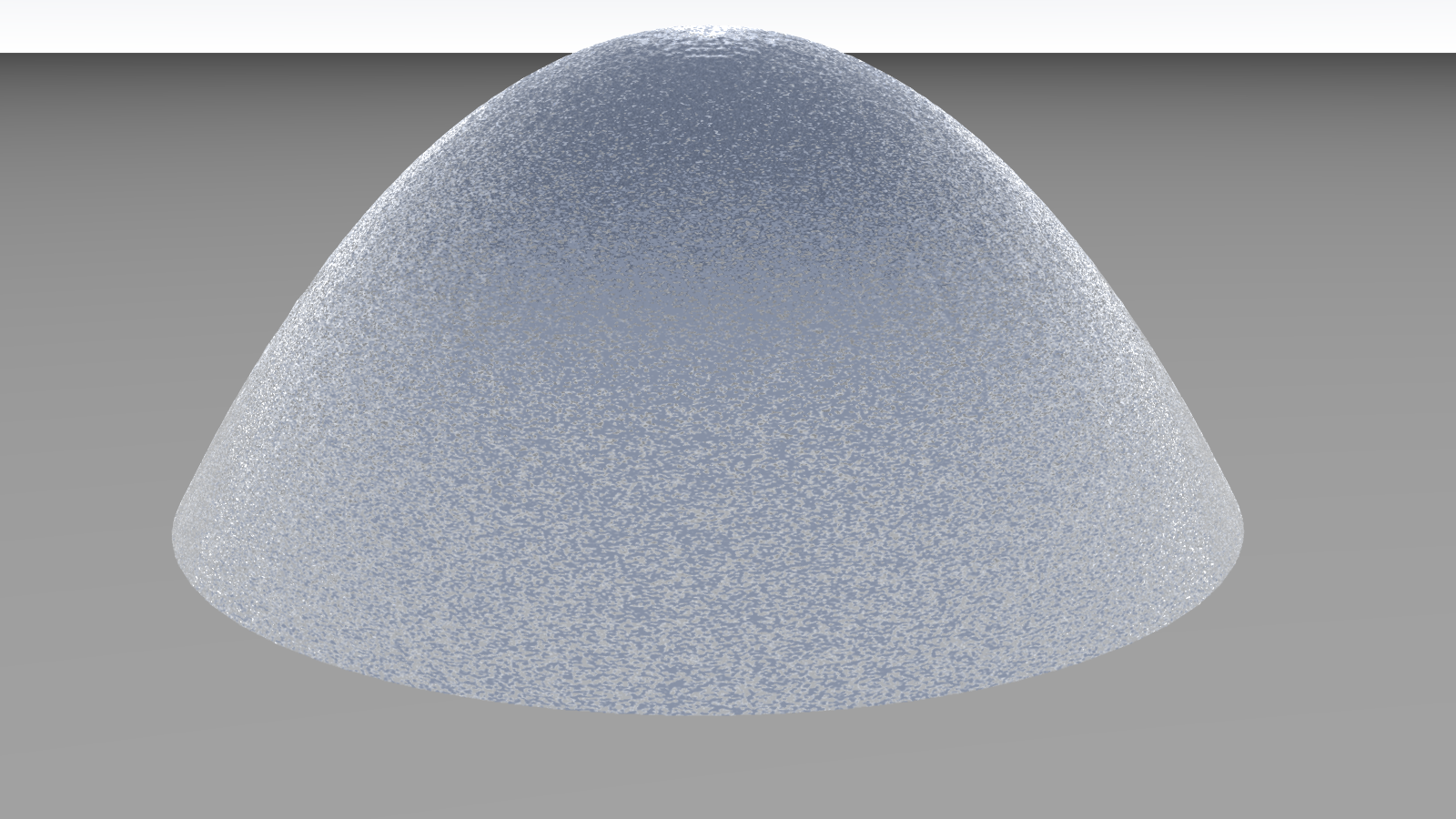
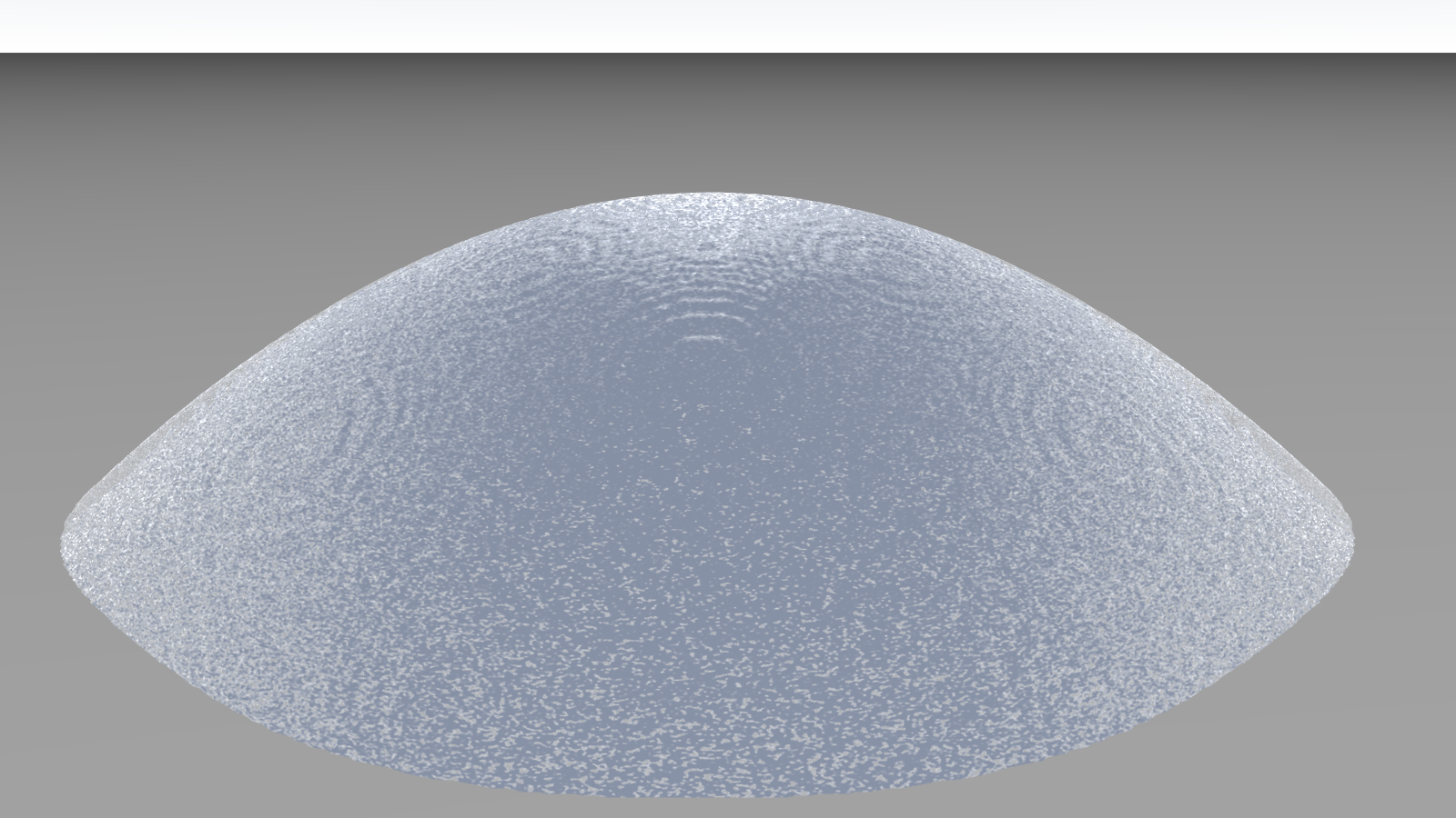
In Fig. 4 we show such an initial shape, with contact angle , and the equilibrium shape with contact angle .
To extract the contact angle from our data we impose that the shape at all times is close to the shape of a spherical cap, such that we are able to calculate the contact angle at any time using the initial angle and radius to obtain the volume
| (27) |
Since our method is mass conserving, the volume of the droplet is by construction conserved. Measuring both the height of the droplet and the diameter of the spherical cap we are able to recalculate the time dependent sphere radius as
| (28) |
and can solve Eq.(27) again for the contact angle . We cross-checked our results with an alternative approach to calculate the angle given by
| (29) |
Let us stress that the shape is indeed very close to a spherical cap. As mentioned in Section II, in fact, a sufficiently accurate finite difference scheme is required, as the one in Eqs. (18-II) Thampi et al. (2013). In particular, we note that the isotropy of the pressure gradient is of utmost importance: a simple scheme with two-point centered derivatives Zhou (2004) yields squared equilibrium droplet shapes.
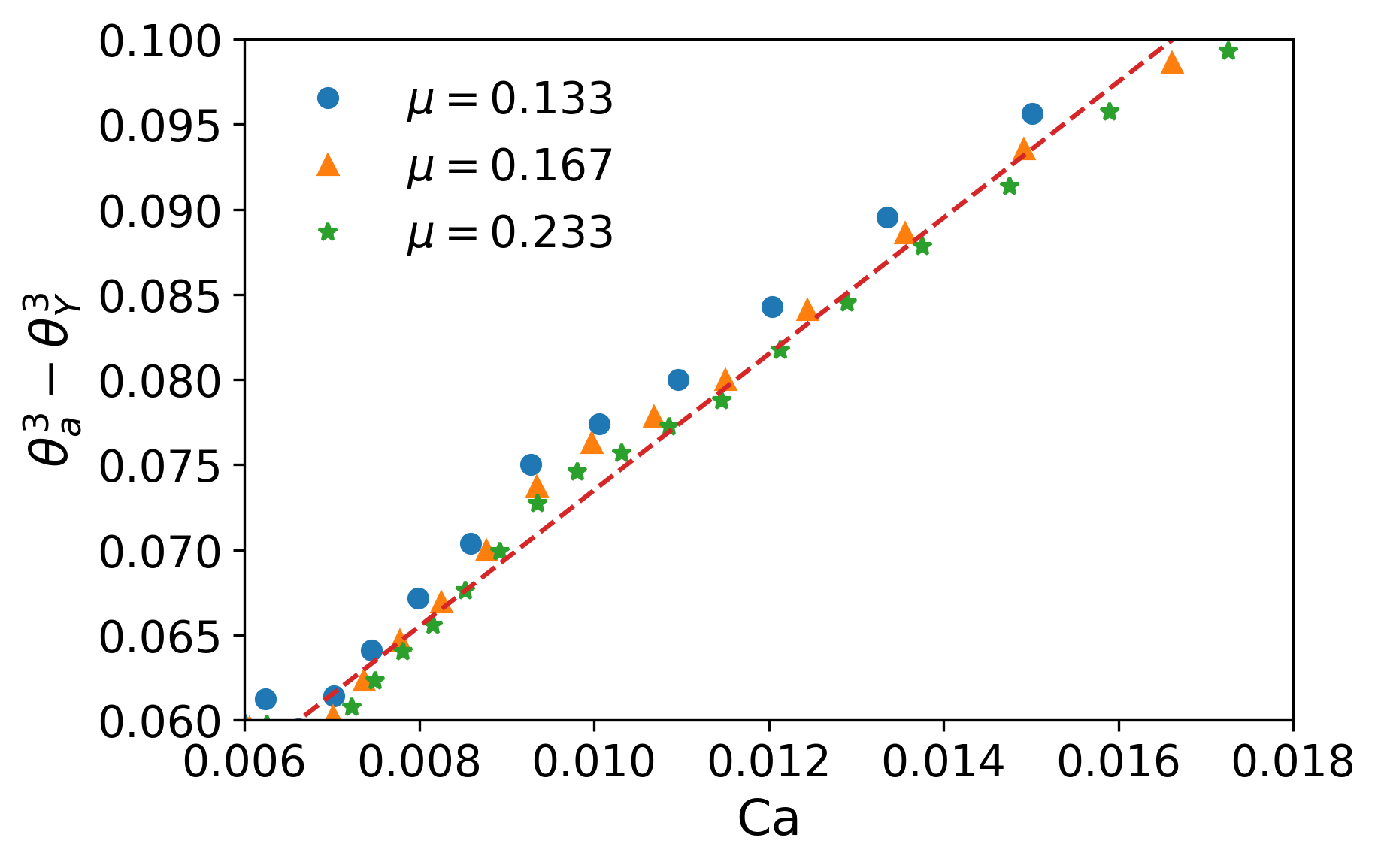
The spreading dynamics can be investigated even more quantitatively in terms of the so-called Cox-Voinov law and Tanner’s law Tanner (1979). The first one relates the apparent contact angle to the velocity of the spreading front (the contact line), at various times, by . The capillary number is defined as Snoeijer and Andreotti (2013). In Fig. 5 we plot vs from a numerical simulation of a spreading drop: a good linear scaling, in agreement with the Cox-Voinov law, is observed, as highlighted by the dashed line.
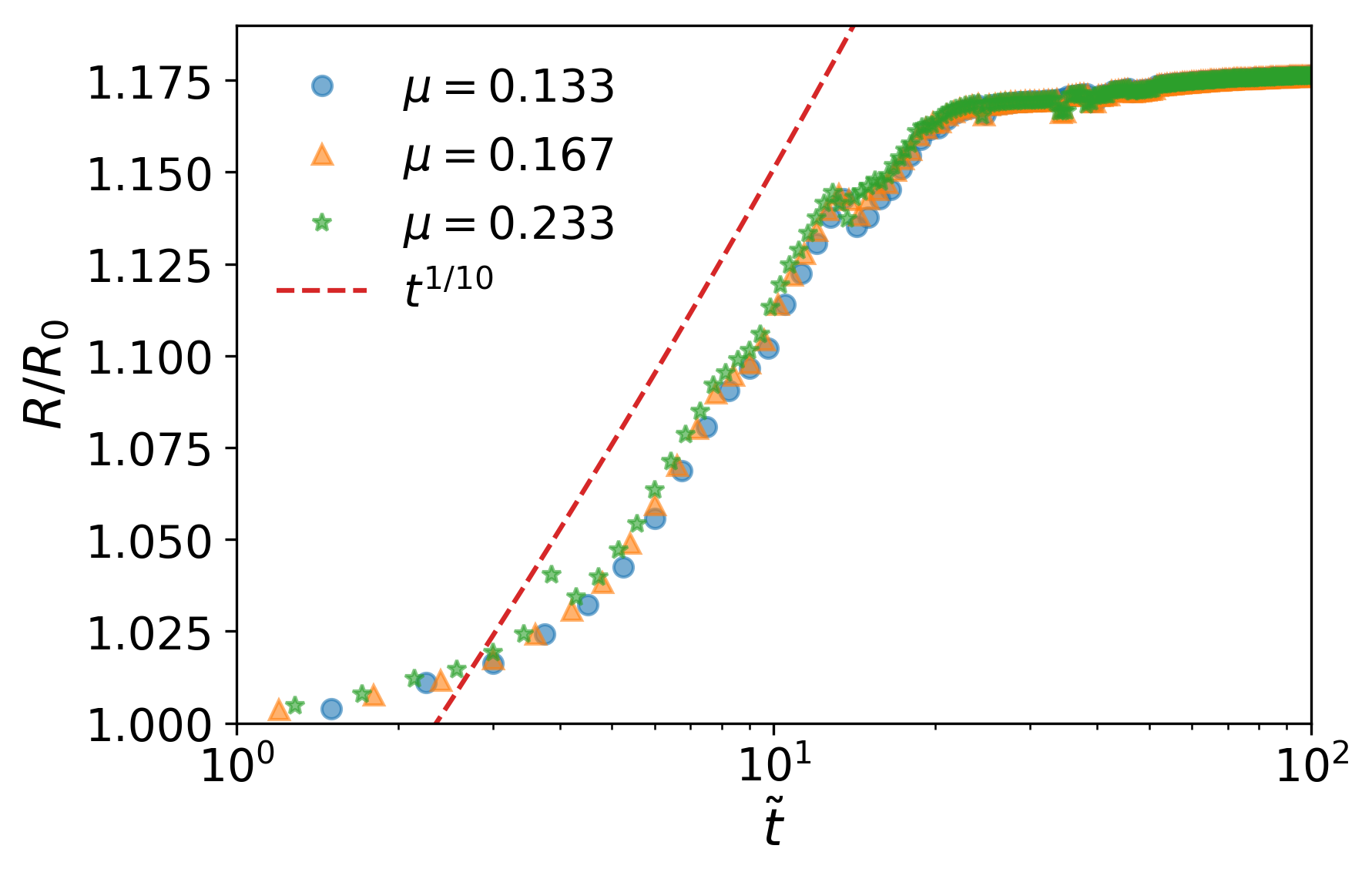
The Tanner’s law which states that the radius of the droplet grows with time as
| (30) |
with the constant being such that . In Fig. 6 we plot the measured radius of the droplet divided by its initial radius as a function of the dimensionless time (here ). For the three viscosities considered in Figs. 5,6 our capillary times are . We see a saturation at because the droplet is very close to its equilibrium shape. During the growth phase the radius follows indeed a power law in with exponent , which is shown by the red dashed line, in agreement with Tanner’s prediction and experimental results Rioboo et al. (2002); Jambon-Puillet et al. (2018); Cazabat and Stuart (1986); Chen (1988). We further notice that within our simulations the droplet needs about to reach its equilibrium shape.
III.3 A Sliding droplet
As a further validation case we consider the sliding of a droplet on an inclined plane. For a droplet to slide over an inclined plane, a minimum tilting angle of the substrate is required Furmidge (1962), which in our case is due to the friction term Eq. (14). Until this critical angle is reached energy is stored in the deformation of the surface as the upper left inset in Fig. 7 shows. Above such a critical angle, a linear relation between the terminal sliding velocity and the gravitational force is observed Podgorski et al. (2001); Kim et al. (2002); Sbragaglia et al. (2014); in dimensionless numbers such behaviour is expressed by
| (31) |
where the capillary number is based on and is the so called Bond number, given by
| (32) |
is the critical Bond number, defined in terms of the critical tilting angle .
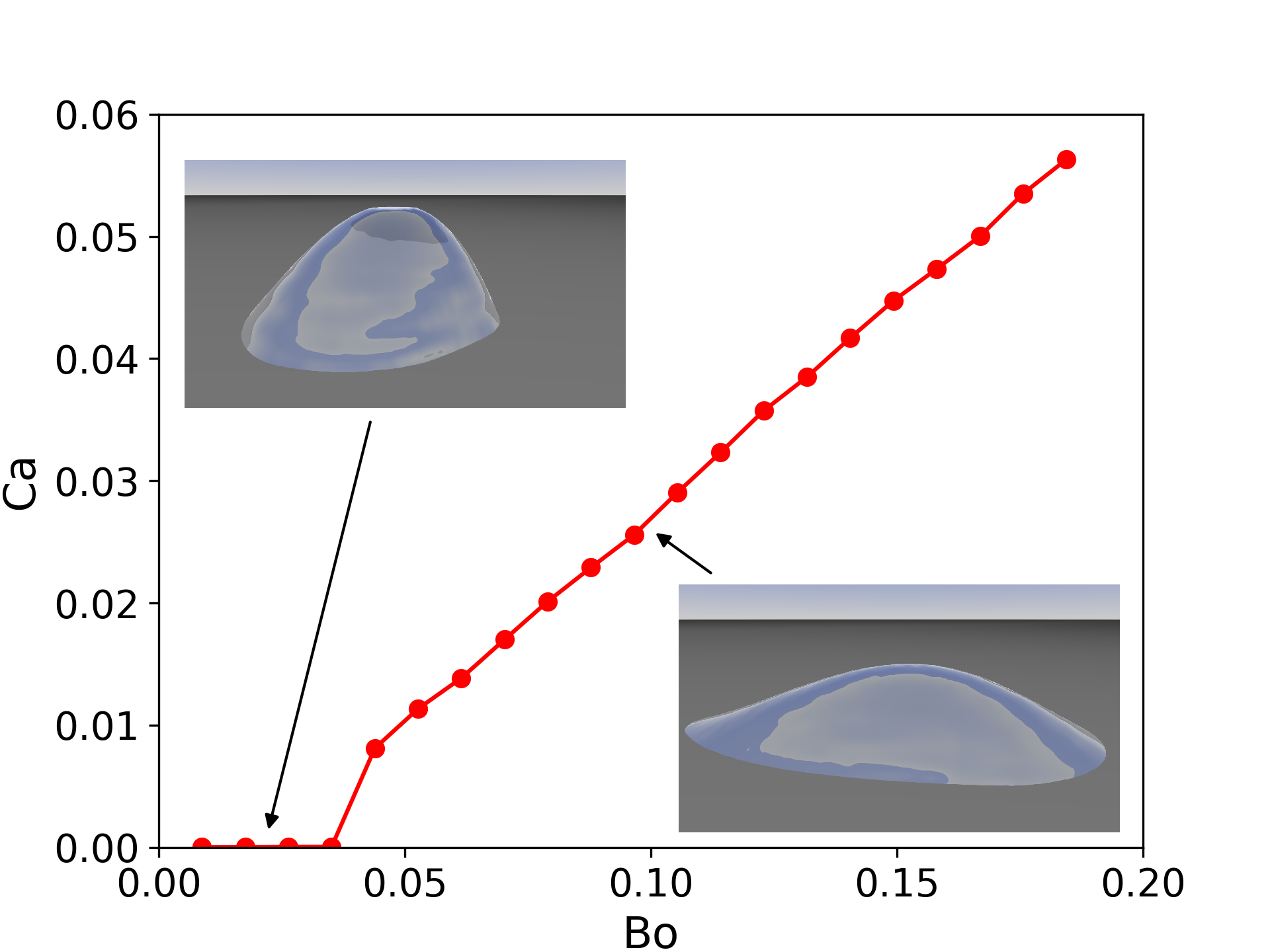
In Fig. 7 we plot vs from our numerical simulations, showing that the phenomenology described by Eq. (31) is indeed reproduced, i.e. the onset of sliding takes place at a finite forcing, beyond which the linear scaling is fulfilled.
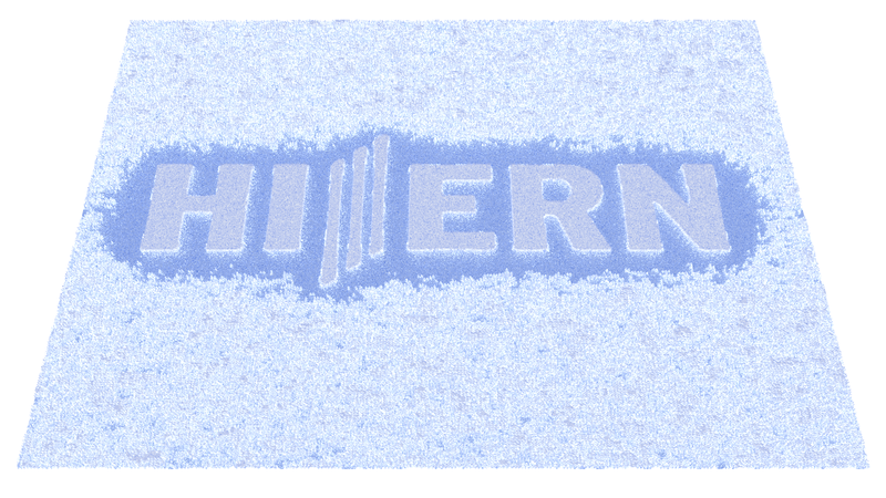

III.4 Dewetting of liquid films
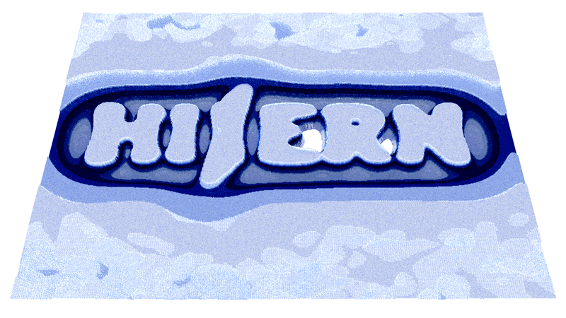
In order to show-case the capabilities of our method in handling more complex physics scenarios, we finally consider the dewetting of a chemically patterned substrate Kargupta and Sharma (2002); Brasjen et al. (2013). This is easily made possible within the code by introducing a space-varying equilibrium contact angle, , in Eq. (12); in this way we can tune the local wettability of the substrate. Fig. 8 shows a liquid film which is initialized with thickness randomly fluctuating in space around its mean value , by a small percentage () of it (panel (a)). A partially wettable substrate is patterned in such a way that the contact angle is lower on a region defining a logo. The total domain contains 512x512 lattice nodes. With this domain size a letter contains around 130 lattice nodes in y-direction and about 60 lattice nodes in x-direction.Using the initial height of the film as characteristic length scale we get a capillary time of . As the film dewets, liquid moves toward the letters of the logo, the surrounding film becomes thinner and eventually the logo becomes visible.
IV Computational aspects
We use OpenACC directives to allow our code to run on accelerator devices, such as Graphics Processing Units (GPUs), while being able, at the same time, to exploit the well known good scaling properties of the LBM on parallel machines Chandrasekaran and Juckeland (2017). OpenACC is particularly versatile in terms of programmability since it only requires a few lines of code to allow us to harness the power of state of the art accelerators. In this sense OpenACC is very similar to OpenMP and more readable as well as much easier to program than CUDA.
The performance of a LBM code is commonly measured in Million Lattice Updates Per Second (MLUPS), defined as
| (33) |
with being the area of the lattice, where are the number of lattice nodes in and directions. The number of iterations is given by . The time needed to compute the interations is called (in seconds). In Tab. 1 we provide benchmark data comparing the performance of a Nvidia GTX 1080TI, a Nvidia Quadro K2200 and a single core of an Intel i7-4790 @ 3.6GHz CPU. Due to the limited amount of memory available on the Quadro K2200, it is not possible to run a simulation of size on this card. Such a simulation requires about 4.8 GB local memory, while the Quadro K2200 only supplies 4 GB. In particular the speedup gained by using a GTX 1080TI is outstanding and corresponds to about 24-92 times the performance of a single core of the Intel CPU. Assuming perfect scaling on the CPU and using all 4 physical cores, the simulation on the GPU would be faster by a factor between 6 and 23. The speedup depends on the size of the lattice and in order to keep the pipelines on the GPU filled, a minimum loop size is needed. In addition, data transfer between host and device is a known bottleneck impacting the performance of GPU based simulations. This is obviously also the case for our code – even though such data transfer is only needed when files are written to disk.
| Lattice/Accelerator | ||||||
|---|---|---|---|---|---|---|
| GTX 1080TI | ||||||
| Quadro K2200 | ||||||
| i7-4790 |
V Conclusions
We have presented a novel lattice Boltzmann model for the numerical simulation of thin liquid film hydrodynamics, featuring explicitly relevant properties of interface physics, such as surface tension and disjoining pressure.
We validated our method against a relevant test case, namely the Rayleigh-Taylor instability, where the critical wavenumber as well as the growth and damping of wavemodes are correctly reproduced. Our simulations of droplets on substrates showed that droplets initiated out of equilibrium attain their equilibrium contact angle and that our method correctly reproduces the Cox-Voinov law as well as Tanner’s law. Furthermore, our approach allows to simulate the dynamics of sliding droplets and even complex dewetting scenarios.
Our OpenACC enabled simulation code allows for a massive improvement of the performance: with modern GPU cards at hand simulations using large lattice sizes and requiring many time steps can be run on a single workstation without the need for access to high performance computing resources.
In the future, we plan to extend our work towards systems which could hardly be tackled by traditional methods: from the dynamics of individual droplets on complex shaped substrates we plan to move to large numbers of droplets in order to understand the statistical properties of collective droplet motion on chemically structured substrates. Finally, a possible application of our method could be the simulation of full lab-on-chip devices with highly resolved channels, junctions, etc..
Acknowledgements.
The authors acknowledge financial support by the Deutsche Forschungsgemeinschaft (DFG) within the Cluster of Excellence “Engineering of Advanced Materials” (project EXC 315) (Bridge Funding). The work has been partly performed under the Project HPC-EUROPA3 (INFRAIA-2016-1-730897), with the support of the EC Research Innovation Action under the H2020 Programme; in particular, S. Z. gratefully acknowledges the support of Consiglio Nazionale delle Ricerche (CNR) and the computer resources and technical support provided by CINECA.Appendix A
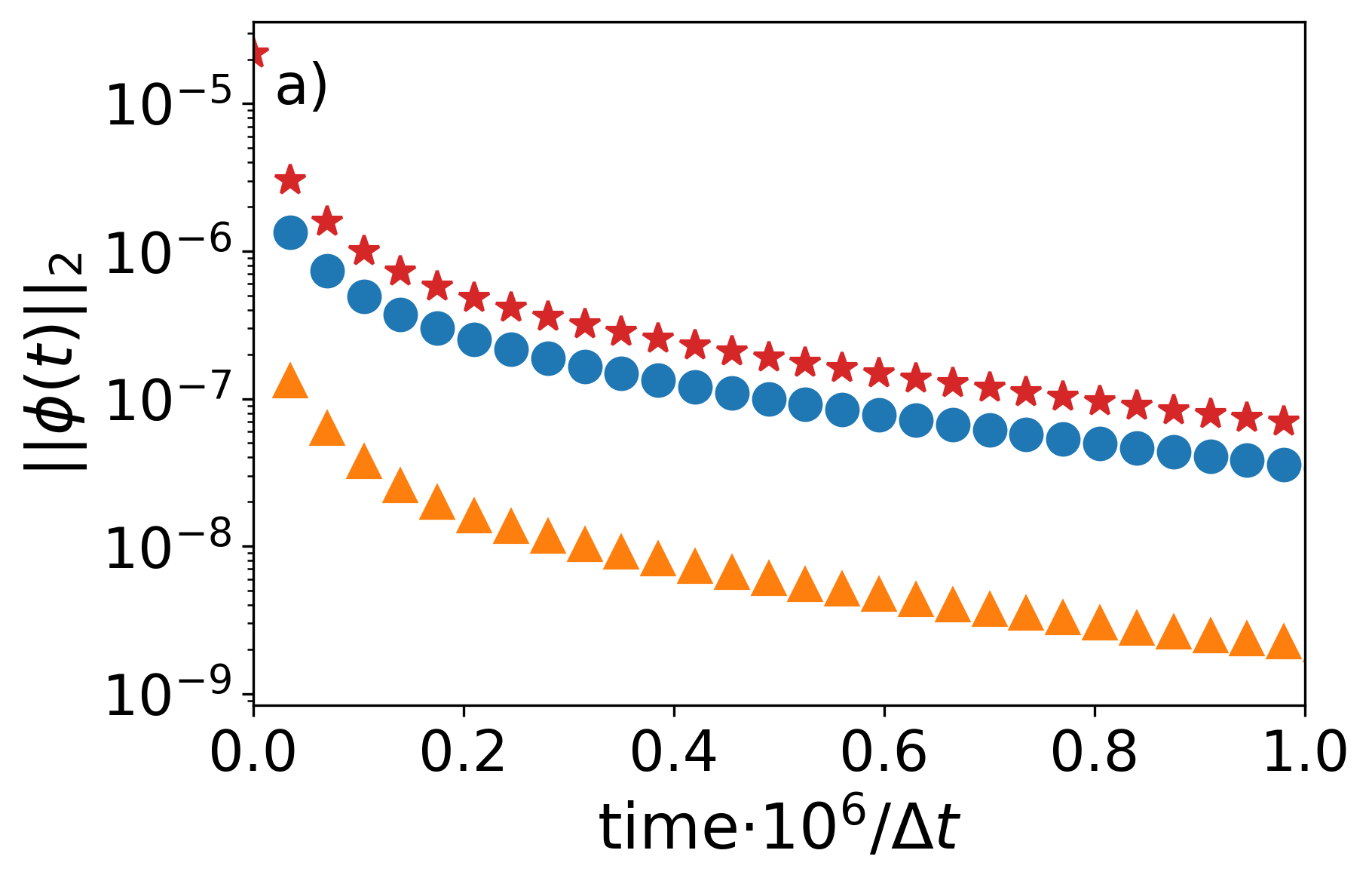
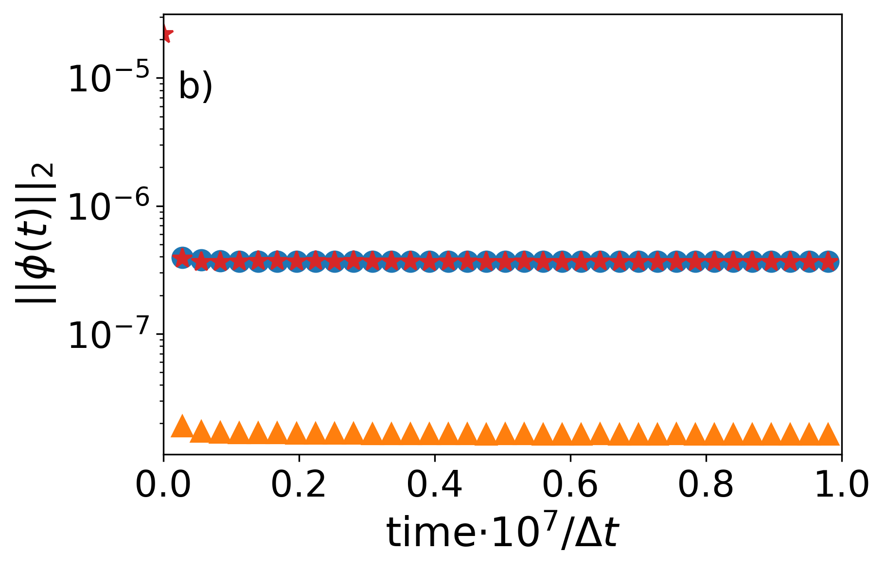
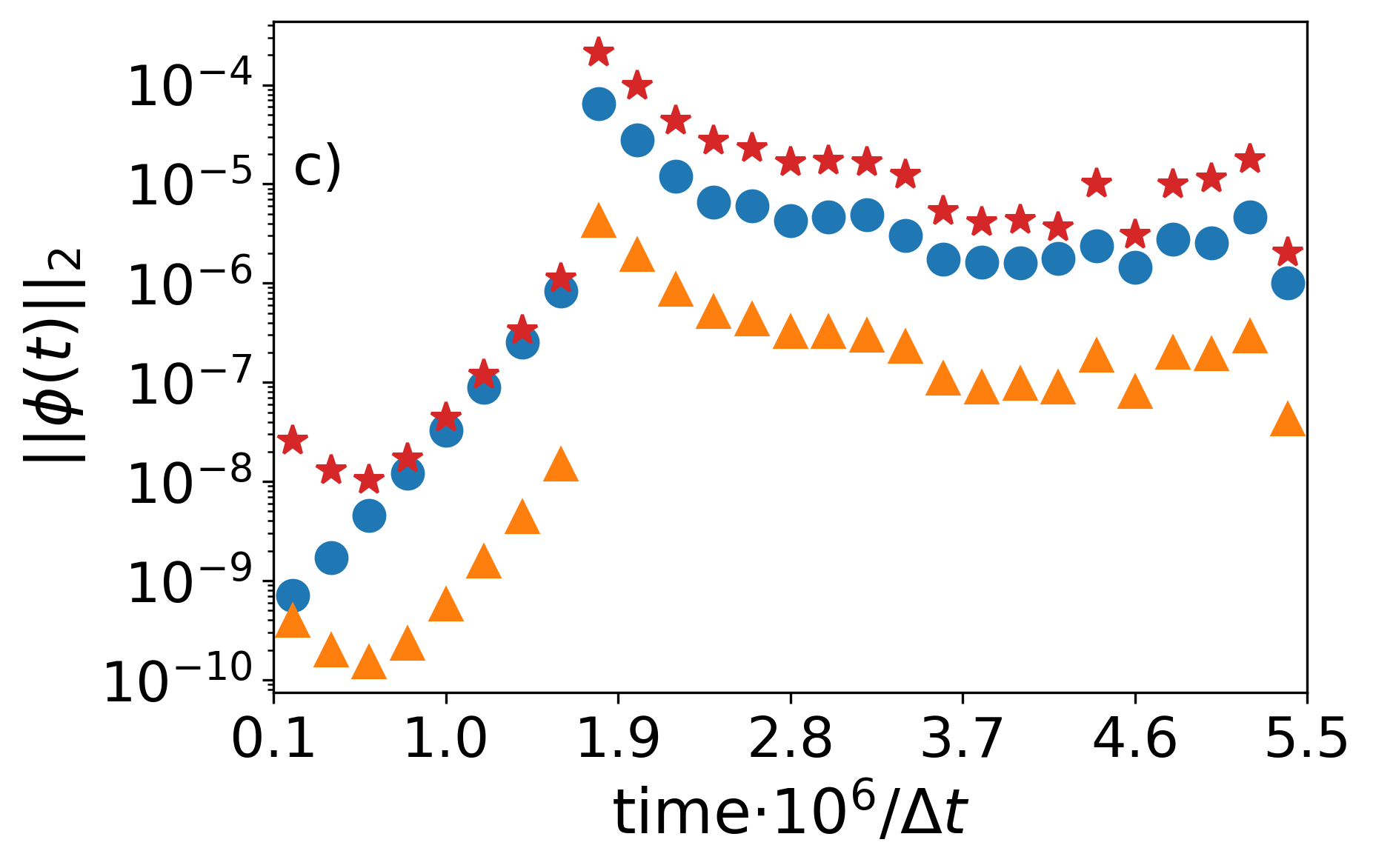
As anticipated above, we provide here a numerical validation of the assumptions on effectively negligible terms that lead from Eq. (9) to Eq. (16). To this aim, we report in Fig. 9, for each of the term under scrutiny, the time evolution of a -norm, defined for a generic scalar field as
| (34) |
where the double sum is extended to the whole two-dimensional domain. Three case-studies are analyzed (corresponding to the three panels in Fig. 9), namely (a) a sessile droplet spreading on a substrate with an equilibrium contact angle smaller than the initial one, (b) a droplet sliding under the action of a body force and (c) the dewetting of a substrate. We compare, for each simulation, the for the -component222Similar results are found also for the -component. of the gradient of the film pressure, , of the friction term, , and of the longitudinal viscous terms, (the advection term, is for all cases orders of magnitude smaller than the other terms, therefore we decided to omit it from the comparisons in figure Fig. 9). We observe that the gradient of the film pressure and the friction are dominant, with the norm of the longitudinal dissipation term being always, roughly, less than of the friction contribution.
References
- de Gennes et al. (2003) P. de Gennes, F. Brochard-Wyart, and D. Quere, Capillarity and Wetting Phenomena: Drops, Bubbles, Pearls, Waves (Springer New York, 2003).
- Focke et al. (2010) M. Focke, D. Kosse, C. Müller, H. Reinecke, and F. von Stetten, Lab Chip 10, 1365 (2010).
- Oron et al. (1997) A. Oron, S. H. Davis, and S. G. Bankoff, Rev. Mod. Phys. 69, 931 (1997).
- Utada et al. (2007) A. S. Utada, L.-Y. Chu, A. Fernández-Nieves, D. R. Link, C. Holtze, and D. A. Weitz, MRS Bulletin 32, 702 (2007).
- Bonn et al. (2009) D. Bonn, J. Eggers, J. Indekeu, J. Meunier, and E. Rolley, Rev. Mod. Phys. 81, 739 (2009).
- Navier (1823) C. L. Navier, Mémoires de l’Académie des sciences de l’Institut de France , 389 (1823).
- Stokes (1842) G. G. Stokes, Transactions of the Cambridge Philosophical Society 7, 439 (1842).
- Reynolds (1886) O. Reynolds, Philos. Trans. R. Soc. London 177, 157 (1886).
- Craster and Matar (2009) R. V. Craster and O. K. Matar, Rev. Mod. Phys. 81, 1131 (2009).
- Mitlin (1993) V. Mitlin, J. Colloid Interface Sci. 156, 491 (1993).
- Becker et al. (2003) J. Becker, G. Grün, R. Seemann, H. Mantz, K. Jacobs, K. R. Mecke, and R. Blossey, Nature Materials 2, 59 (2003).
- Succi (2001) S. Succi, The lattice Boltzmann equation for Fluid Dynamics and beyond (Oxford Science Publications, 2001).
- Salmon (1999) R. Salmon, J. Mar. Res. 57, 503 (1999).
- Dellar (2002) P. J. Dellar, Phys. Rev. E 65, 036309 (2002).
- Zhou (2004) J. G. Zhou, Lattice Boltzmann methods for shallow water flows, Vol. 4 (Springer, 2004).
- Van Thang et al. (2010) P. Van Thang, B. Chopard, L. Lefèvre, D. A. Ondo, and E. Mendes, J. Comput. Phys. 229, 7373 (2010).
- Wolf-Gladrow (2001) D. A. Wolf-Gladrow, Lattice-Gas Cellular Automata and Lattice Boltzmann Models: An Introduction (Springer, 2001).
- Qian et al. (1992) Y. H. Qian, D. d’Humières, and P. Lallemand, Europhys. Lett. 17, 479 (1992).
- Shan et al. (2006) X. Shan, X. F. Yuan, and H. Chen, J. Fluid. Mech. 550, 413 (2006).
- Chapman and Cowling (1939) S. Chapman and T. G. Cowling, The mathematical theory of non-uniform gases (Cambridge University Press, 1939).
- Enskog (1917) D. Enskog, Kinetische Theorie der Vorgänge in mässig verdünnten Gasen (PhD Thesis, 1917).
- Thiele (2014) U. Thiele, Adv. Colloid Interface Sci. 206, 399 (2014).
- Moulton and Lega (2013) D. E. Moulton and J. Lega, Eur. J. Appl. Math. 24, 887–920 (2013).
- Fischer and Grün (2018) J. Fischer and G. Grün, SIAM J. Math. Anal. 50, 411 (2018).
- Diez et al. (2009) J. A. Diez, A. G. González, and L. Kondic, J. Phys. Conf. Ser. 166, 012009 (2009).
- Wilczek et al. (2017) M. Wilczek, W. Tewes, S. Engelnkemper, S. V. Gurevich, and U. Thiele, Phys. Rev. Lett. 119, 204501 (2017).
- Wedershoven et al. (2014) H. M. J. M. Wedershoven, C. W. J. Berendsen, J. C. H. Zeegers, and A. A. Darhuber, Appl. Phys. Lett. 104, 054101 (2014).
- Rocca et al. (2012) M. L. Rocca, C. Adduce, V. Lombardi, G. Sciortino, and R. Hinkelmann, International Journal for Numerical Methods in Fluids 70, 1048 (2012), https://onlinelibrary.wiley.com/doi/pdf/10.1002/fld.2742 .
- Reynolds (1883) O. Reynolds, Philos. Trans. R. Soc. London 174, 935 (1883).
- Sommerfeld (1908) A. Sommerfeld, International Congress of Mathematicians 3, 116 (1908).
- Calì et al. (1992) A. Calì, S. Succi, A. Cancelliere, R. Benzi, and M. Gramignani, Phys. Rev. A 45, 5771 (1992).
- Kingdon and Schofield (1992) R. D. Kingdon and P. Schofield, Journal of Physics A: Mathematical and General 25, L907 (1992).
- Chen et al. (1995) S. Chen, S. Dawson, G. Doolen, D. Janecky, and A. Lawniczak, Computers & Chemical Engineering 19, 617 (1995), applications of Parallel Computing.
- Weimar and Boon (1996) J. R. Weimar and J. P. Boon, Physica A: Statistical Mechanics and its Applications 224, 207 (1996), dynamics of Complex Systems.
- Swift et al. (1996) M. R. Swift, E. Orlandini, W. R. Osborn, and J. M. Yeomans, Phys. Rev. E 54, 5041 (1996).
- Lishchuk et al. (2003) S. V. Lishchuk, C. M. Care, and I. Halliday, Phys. Rev. E 67, 036701 (2003).
- Gunstensen et al. (1991) A. K. Gunstensen, D. H. Rothman, S. Zaleski, and G. Zanetti, Phys. Rev. A 43, 4320 (1991).
- Junk and Klar (2000) M. Junk and A. Klar, SIAM Journal on Scientific Computing 22, 1 (2000), https://doi.org/10.1137/S1064827599357188 .
- Thampi et al. (2013) S. P. Thampi, S. Ansumali, R. Adhikari, and S. Succi, J. Comp. Phys. 234, 1 (2013).
- Rayleigh (1900) L. Rayleigh, Scientific Papers 2, 200 (1900).
- Taylor (1950) G. Taylor, Proc. R. Soc. London Ser. A 201, 192 (1950).
- Kull (1991) H. Kull, Physics Reports 206, 197 (1991).
- Sharp (1984) D. H. Sharp, Physica D 12, 3 (1984).
- de Gennes (1985) P. G. de Gennes, Rev. Mod. Phys. 57, 827 (1985).
- Tanner (1979) L. H. Tanner, Journal of Physics D: Applied Physics 12, 1473 (1979).
- Snoeijer and Andreotti (2013) J. H. Snoeijer and B. Andreotti, Annu. Rev. Fluid Mech. 45, 269 (2013).
- Rioboo et al. (2002) R. Rioboo, M. Marengo, and C. Tropea, Experiments in fluids 33, 112 (2002).
- Jambon-Puillet et al. (2018) E. Jambon-Puillet, O. Carrier, N. Shahidzadeh, D. Brutin, J. Eggers, and D. Bonn, Journal of Fluid Mechanics 844, 817–830 (2018).
- Cazabat and Stuart (1986) A. Cazabat and M. C. Stuart, The Journal of Physical Chemistry 90, 5845 (1986).
- Chen (1988) J.-D. Chen, Journal of Colloid and Interface Science 122, 60 (1988).
- Furmidge (1962) C. Furmidge, J. Colloid Sci. 17, 309 (1962).
- Podgorski et al. (2001) T. Podgorski, J.-M. Flesselles, and L. Limat, Phys. Rev. Lett. 87, 036102 (2001).
- Kim et al. (2002) H.-Y. Kim, H. Lee, and B. Kang, J. Colloids Surf. Sci. 247, 372 (2002).
- Sbragaglia et al. (2014) M. Sbragaglia, L. Biferale, G. Amati, S. Varagnolo, D. Ferraro, G. Mistura, and M. Pierno, Phys. Rev. E 89, 012406 (2014).
- Kargupta and Sharma (2002) K. Kargupta and A. Sharma, Langmuir 18, 1893 (2002).
- Brasjen et al. (2013) B. J. Brasjen, H. Gu, and A. A. Darhuber, Microfluid Nanofluidics 14, 669 (2013).
- Chandrasekaran and Juckeland (2017) S. Chandrasekaran and G. Juckeland, OpenACC for Programmers: Concepts and Strategies, 1st ed. (Addison-Wesley Professional, 2017).