Multi-step self-guided pathways for shape-changing metamaterials
Multi-step pathways, constituted of a sequence of reconfigurations, are central to a wide variety of natural and man-made systems. Such pathways autonomously execute in self-guided processes such as protein folding1 and self-assembly2; 3; 4; 5, but require external control in macroscopic mechanical systems, provided by, e.g., actuators in robotics 6; 7; 8; 9 or manual folding in origami10; 8; 11; 12. Here we introduce shape-changing mechanical metamaterials, that exhibit self-guided multi-step pathways in response to global uniform compression. Their design combines strongly nonlinear mechanical elements with a multimodal architecture that allows for a sequence of topological reconfigurations, i.e., modifications of the topology caused by the formation of internal self-contacts. We realized such metamaterials by digital manufacturing, and show that the pathway and final configuration can be controlled by rational design of the nonlinear mechanical elements. We furthermore demonstrate that self-contacts suppress pathway errors. Finally, we demonstrate how hierarchical architectures allow to extend the number of distinct reconfiguration steps. Our work establishes general principles for designing mechanical pathways, opening new avenues for self-folding media11; 12, pluripotent materials13; 9, and pliable devices14 in, e.g., stretchable electronics and soft robotics15.
Mechanical metamaterials are structured forms of matter that can be designed to exhibit a wide range of anomalous properties16, including negative responses17, topological polarization18, non-reciprocity19 and shape morphing 20; 9. These striking deviations from ordinary elasticity ultimately emerge from soft deformation modes, encoded in their internal architecture 16; 18. Most metamaterials feature a single soft mode, which limits their deformations to single-step pathways 21; 22; 20; 23. Multi-step deformations, as well as other advanced functionalities, require designs featuring a high dimensional deformation space spanned by multiple soft modes 13; 24; 25; 26; 27; 9. However, when actuated, competition between those soft modes leads to frustration 11; 12 and spatial decay of functionality 23. Hence, multi-modal mechanical metamaterials are sofar either actuated without explicit control over their reconfiguration pathways13; 25, or require the use of multiple actuators, one for each degree of freedom27; 9. In contrast, processes such as self-assembly5 and protein folding1 exhibit robust multi-step pathways without the need for such external control. Here we raise the question whether one can design and create mechanical metamaterials that translate global forcing into a self-guided multi-step pathway of reconfigurations.
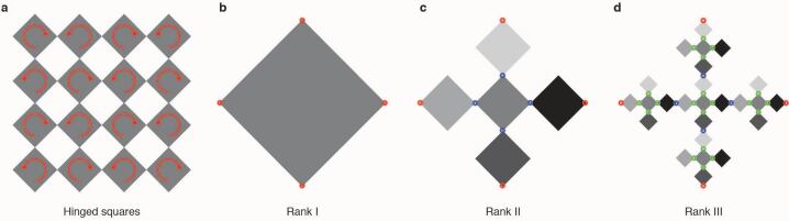
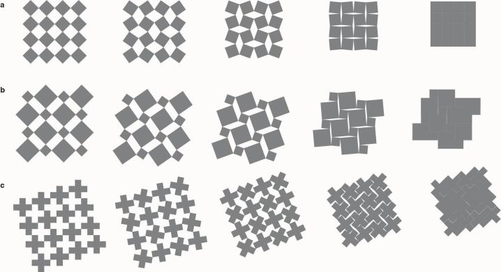
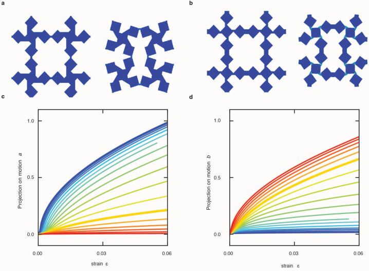
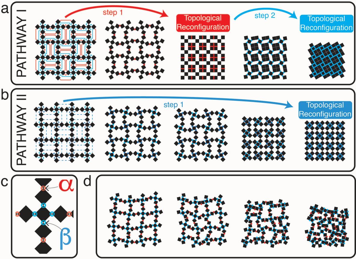
To address this challenge, we consider two-dimensional metamaterials consisting of diluted lattices of freely hinged squares. We design a unit cell that consist of a cross-shaped pattern of five squares, leading to a multi-modal metamaterial of squares, which allows for the formation of self-contacts between initially separated elements and features zero energy modes (Fig. 1 and Methods). Crucially, this structural design admits a two-step deformation pathway, characterized by the deformation angles and (Fig. 1a,c). In the first step of this pathway I, the -links should fold while the -links should remain fixed until self-contacts, which change the topology of the material, are formed. This topological reconfiguration spawns a daughter structure at finite compression. In the second step, the -links should remain fixed and the -links should fold until the system is fully compacted (Fig. 1a). This is but one possible deformation path, however, and our structure admits a myriad of other pathways, some highly structured (Fig. 1b and Methods), most disordered (Fig. 1d).
To obtain a specific deformation path in response to global compression, we augment this structural design with suitably tailored mechanical interactions, connecting the squares with beam-like links of varying thickness and (Methods). This replaces the zero energy modes by soft modes, whose energetics are controlled by the links. Crucially, these beams also introduce a well defined critical compressive load above which the non-linear buckling instability causes spontaneous bending of the corresponding link28. Intuitively, pathway I requires that , whereas pathway II requires (Fig. 1). The mode structure in the corresponding asymptotic limits reveals an important qualitative difference: whereas the undeformed metamaterial has a single soft mode for , it has many (precisely ) soft modes for , as the numerous soft links can deform in myriad manners in this case (Methods). This counting argument suggests that pathway I will be much easier to realize than pathway II: we refer to pathway I as a natural pathway.
To rationally design the links to obtain either pathway I or II, we have analysed the modes and instabilities of a representative volume element, a so-called super cell consisting of a grid of unit cells, as function of and (Methods). This modal analysis substantiates our counting-based argument. First, we find that the ratio , rather than the individual thicknesses, plays the crucial role. Moreover, for small , the first buckling mode corresponds to the first step in pathway I, with other modes strongly suppressed. Finally, for large , even though the first buckling mode coincides with the first step in pathway II, other modes remain in competition. Based on the details of this analysis we extract specific design guidelines for the rational design of the link parameters (Methods).
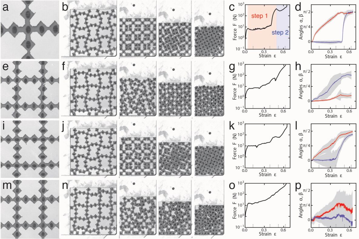
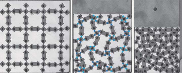
We illustrate our approach experimentally. We used a waterjet cutter to fabricate reconfigurable metamaterials with squares of size mm out of rubber sheets that are mm thick (this prevents out of plane buckling). We then actuated their deformation pathways by applying a uniform equi-biaxial strain while tracking the compressive force, the motion of each element and the evolution of the folding angles and (see Methods). We focus on four different samples that share the same structural design, but differ in their and links, which are designed to obtain one of four specific pathways (Fig. 2a,e,i,m).
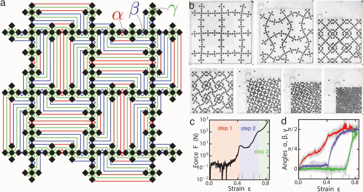
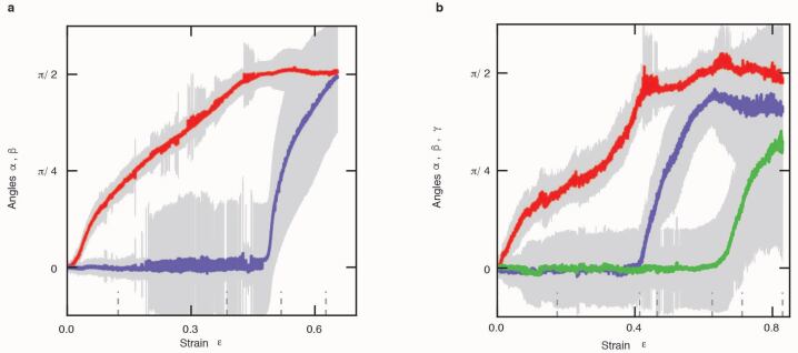
We first design a metamaterial that follows the two-step pathway I. Here, following our design guidelines (Methods) we take mm and mm (Fig. 2a). Under compression, the -links buckle at a strain of , triggering the counter-rotation mode 22 and the first step of the reconfiguration pathway (Fig. 2b). Further compression does not significantly increase the force 28, preventing buckling of the stronger links, until self-contacts are formed at a strain of . The ensuing topological reconfiguration gives rise to a daughter structure with only one soft mode governed by the -links. Further compression leads to a steep rise in the compressive force which triggers the buckling of the -links, initiating the second reconfiguration step, which continues until the structure is fully compressed (Fig. 2b). The compressive force clearly evidences the plateaus associated with buckling and the rapid increase associated with the formation of self-contacts (Fig. 2c). This multi-step pathway is fully consistent with the theoretical pathway I, as further shown by the distinct evolution of the angles and as function of strain (Fig. 2d and Methods). Different geometries can be designed that show similar multi-step pathways under uniaxial compression (Methods). Hence, the combination of self-contacts, buckling, and topological reconfiguration enables multi-step sequences where buckling initiates bending, sufficient bending—or folding—creates self-contacts and topological reconfigurations, which in turn trigger more buckling events.
Successful execution of a structured pathway requires error-correcting mechanisms, that compensates for distortions caused by boundary frustration and manufacturing imperfections. We note that while the scatter in and grows significantly during each deformation step, it sharply reduces upon reaching self-contact (Fig. 2d). This reduction results from the self-alignment of the flat interfaces of contacting squares, and underlies the remarkable feature of our metamaterials that the fully compressed structure is highly ordered. Hence, self-contacts have a crucial error-correcting role, thus ensuring a robust execution of a pathway.
Pathway II is harder to realize experimentally. Even for large we observe that while the deformation is qualitatively similar to pathway II, it is still quite disordered, which we attribute to the issue of competition of multiple modes (Methods).
To address this issue, we now demonstrate that symmetry breaking perturbations can suppress the undesired modes and promote pathway II. We introduce a new design parameter , and laterally offset the -links over a distance with alternating chirality (Fig. 2e and Methods). The design guideline that we have extracted from our numerical analysis suggests that such symmetry breaking offsets are sufficient to favour pathway II already for (Methods). We thus created a second sample with such offsets, took mm mm, and find that under compression, the slender -links bend, the thicker -links remain essentially straight, and a single-step path towards a different end state ensues (Fig. 2e-h).
We note that offsets can also be used to modify and probe pathway I. Fixing with constant chirality (Fig. 2i,m) and gradually increasing , we find experimentally that up to , the broken symmetry causes blurring of the pathway and larger scatter in the bending angles, but pathway I still ensues and the fully folded state is still reached, illustrating the robustness of the natural pathway against perturbations (Fig. 2i-l; mm, mm). For even larger , we observe a disordered pathway (Fig. 2m-p, where mm, mm). These examples with offset links demonstrate that symmetry breaking provides an efficient strategy to steer the deformation pathway.
Finally, the hierarchical nature of our structural design can be leveraged to create metamaterials with a three-step natural pathway. Our two-step design results from replacing each square in a rotating square mechanism21 with a cross pattern of five smaller squares (Methods). To obtain a three-step sequence, we replace each square in the unit cell of the two-step design by a smaller cross-shaped subpattern (Methods). The resulting unit cell consists of 25 small squares that form a generation-2 box fractal; we create a metamaterial out of nine of these unit cells which, in the limit of perfect hinges, has 216 zero modes (Fig. 3a and Methods). We aim to obtain a three-step pathway by sequential folding of the , and links, which leads to an intricate web of self-contacts (Fig. 3a and Methods). We tailor the three classes of links to set up such pathway by taking mm mm mm. Upon biaxial compression, we observe a three-step sequence of reconfigurations, leading to a fully closed, highly ordered structure (See Fig. 3b and Supplementary Video 2). The compressional force and bending angles further evidence the three distinct steps of this reconfiguration pathway (Fig. 3c-d), demonstrating that our design strategy can naturally be used to achieve complex, multiple-step pathways that are remarkably robust.
To conclude, we have shown that hierarchical structures dressed with mechanical switches based on buckling and self-contacts feature self-guided topological reconfigurations that are robust to imperfections. Our designs are purely geometric and can thus be applied over a range of scales, and they are passive, thus alleviating the need for external control. We expect our approach to considerably enhance the potential of, e.g., reconfigurable materials13; 29; 30; 9, soft robotics8, origami metamaterials10; 11; 12, and stretchable electronics13; 14.
Acknowledgements. We thank J. Mesman and D. Ursem for outstanding technical support. We acknowledge Z. Zeravcic and A. Murugan for discussions. We acknowledge funding from the Netherlands Organization for Scientific Research through grants VICI No. NWO-680-47-609 (M.v.H.) and VENI NWO-680-47-445 (C.C).
Author Contribution. All authors conceived the project. C.C. and M.v.H. developed the theoretical models and C.C. performed the numerical simulations. C.C., A.S. and F.V. designed and carried out the experiments. C.C. and M.v.H. wrote the manuscript.
References
- Dobson (2003) C. M. Dobson, “Protein folding and misfolding,” Nature 426, 884–90 (2003).
- Winfree et al. (1998) E. Winfree, F. Liu, L. A. Wenzler, and N. C. Seeman, “Design and self-assembly of two-dimensional dna crystals,” Nature 394, 539–44 (1998).
- Wei et al. (2012) B. Wei, M. Dai, and P. Yin, “Complex shapes self-assembled from single-stranded dna tiles,” Nature 485, 623–6 (2012).
- Chen et al. (2011) Q. Chen, S. C. Bae, and S. Granick, “Directed self-assembly of a colloidal kagome lattice,” Nature 469, 381–4 (2011).
- Zeravcic and Brenner (2014) Z. Zeravcic and M. P. Brenner, “Self-replicating colloidal clusters,” Proc. Natl. Ac. Sc. U. S. A. 111, 1748–1753 (2014).
- Zykov et al. (2005) V. Zykov, E. Mytilinaios, B. Adams, and H. Lipson, “Robotics: self-reproducing machines,” Nature 435, 163–4 (2005).
- Shepherd et al. (2011) R. F. Shepherd et al., “Multigait soft robot,” Proc. Natl. Ac. Sc. U. S. A. 108, 20400–3 (2011).
- Felton et al. (2014) S. Felton, M. Tolley, E. Demaine, D. Rus, and R. Wood, “Applied origami. a method for building self-folding machines,” Science 345, 644–6 (2014).
- Overvelde et al. (2017) J. T. Overvelde, J. C. Weaver, C. Hoberman, and K. Bertoldi, “Rational design of reconfigurable prismatic architected materials,” Nature 541, 347–352 (2017).
- Waitukaitis et al. (2015) S. Waitukaitis, R. Menaut, B. G. Chen, and M. van Hecke, “Origami multistability: from single vertices to metasheets,” Phys. Rev. Lett. 114, 055503 (2015).
- Pinson et al. (2017) M. B. Pinson et al., “Self-folding origami at any energy scale,” Nat. Comm. 8, 15477 (2017).
- Stern et al. (2017) M. Stern, M. Pinson, and A. Murugan, “The difficulty of folding self-folding origami,” Phys. Rev. X 7, 041070 (2017).
- Cho et al. (2014) Y. Cho et al., “Engineering the shape and structure of materials by fractal cut,” Proc. Natl. Ac. Sc. U. S. A. 111, 17390–5 (2014).
- Xu et al. (2015) S. Xu et al., “Materials science. assembly of micro/nanomaterials into complex, three-dimensional architectures by compressive buckling,” Science 347, 154–9 (2015).
- Rogers et al. (2016) J. Rogers, Y. Huang, O. G. Schmidt, and D. H. Gracias, “Origami mems and nems,” MRS Bulletin 41, 123–129 (2016).
- Bertoldi et al. (2017) K. Bertoldi, V. Vitelli, J. Christensen, and M. van Hecke, “Flexible mechanical metamaterials,” Nat. Rev. Mater. 2, 17066 (2017).
- Bertoldi et al. (2010) K. Bertoldi, P. M. Reis, S. Willshaw, and T. Mullin, “Negative poisson’s ratio behavior induced by an elastic instability,” Adv. Mater. 22, 361–366 (2010).
- Huber (2016) S. D. Huber, “Topological mechanics,” Nat. Phys. 12, 621–623 (2016).
- Coulais et al. (2017a) C. Coulais, D. Sounas, and A. Alù, “Static non-reciprocity in mechanical metamaterials,” Nature 542, 461–464 (2017a).
- Coulais et al. (2016) C. Coulais, E. Teomy, K. de Reus, Y. Shokef, and M. van Hecke, “Combinatorial design of textured mechanical metamaterials,” Nature 535, 529–531 (2016).
- Grima and Evans (2000) J. N. Grima and K. E. Evans, “Auxetic behavior from rotating squares,” J. Mater. Sc. Lett. 19, 1563–1565 (2000).
- Mullin et al. (2007) T. Mullin, S. Deschanel, K. Bertoldi, and M. C. Boyce, “Pattern transformation triggered by deformation,” Phys. Rev. Lett. 99, 084301 (2007).
- Coulais et al. (2017b) C. Coulais, C. Kettenis, and M. van Hecke, “A characteristic lengthscale causes anomalous size effects and boundary programmability in mechanical metamaterials,” Nat. Phys. 14, 40-44 (2018).
- Gatt et al. (2015) R. Gatt et al., “Hierarchical auxetic mechanical metamaterials,” Sci. Rep. 5, 8395 (2015).
- Tang et al. (2015) Y. Tang et al., “Design of hierarchically cut hinges for highly stretchable and reconfigurable metamaterials with enhanced strength,” Adv. Mater. 27, 7181–90 (2015).
- Mousanezhad et al. (2015) D. Mousanezhad et al., “Hierarchical honeycomb auxetic metamaterials,” Sci. Rep. 5, 18306 (2015).
- Overvelde et al. (2016) J. T. Overvelde et al., “A three-dimensional actuated origami-inspired transformable metamaterial with multiple degrees of freedom,” Nat. Comm. 7, 10929 (2016).
- Coulais et al. (2015) C. Coulais, J. T. B. Overvelde, L. A. Lubbers, K. Bertoldi, and M. van Hecke, “Discontinuous buckling of wide beams and metabeams,” Phys. Rev. Lett. 115, 044301 (2015).
- Blees et al. (2015) M. K. Blees et al., “Graphene kirigami,” Nature 524, 204–7 (2015).
- Zhang et al. (2015) Y. Zhang et al., “A mechanically driven form of kirigami as a route to 3d mesostructures in micro/nanomembranes,” Proc. Natl. Ac. Sc. U. S. A. 112, 11757–64 (2015).
- Coulais (2016) C. Coulais, “Periodic cellular materials with nonlinear elastic homogenized stress-strain response at small strains,” Int. J. Solids Struct. 97-98, 226-238 (2016).
I Methods
I.1 Hierarchical Design
The architecture of our metamaterials is based on an rotating square mechanism (Extended Data Fig. ED1a). We see this as the first rank in a hierarchy, and for increasing rank, replace each square building block by a sub-pattern of five smaller squares; this construction is known as generating a so-called box fractal (Extended Data Fig. ED1b-d). For an pattern of units of rank , the number of squares equals . These are connected by -links that connect different unit cells. For there are in addition internal -links per unit, and for there are in addition internal -links. In general, going from rank to rank yields additional internal links. For general , this yields connections.
I.2 Hinged Tessellations
Hinged tessellations are freely hinging structures that can be folded into a fully area filing structure. The rotating square mechanism is an example of a hinged tessellation (Extended Data Fig. ED2a). Considering pathways in our hierarchical metamaterials, we also encounter variations on the rotating square mechanism with unequal squares (Extended Data Fig. ED2b) and crosses (Extended Data Fig. ED2c); both are hinged tessellations and can form area filling structures with multiple self-contacts.
I.3 Zero Modes
When the links between the squares are completely flexible, a simple Maxwell counting argument allows to determine the number of zero modes. We start from three degrees of freedom per square (translation and rotation), and subtract two constraints for each connection, as well as three global degrees of freedom (global translation and rotation). This yields a simple expression for , the number of internal degrees of freedom:
| (1) |
It can readily be verified that for , , yielding 61 internal zero modes for the , hierarchy 2 structures that we show in Fig. 1 and 2 of the main text, and that for , , yielding 216 internal zero modes for our , hierarchy 3 structure, shown in Fig. 3 of the main text.
To count the number of soft modes for the limit , one can consider the case that the -links are stiff, the -links are floppy, resulting in a structure which is equivalent to a rotating square mechanism with one degree of freedom21. To count the number of soft modes for the limit , for the case, one can consider the case that the -links are floppy and the -links are stiff; these links now impose instead of 2 constraints, so that an additional constraints must be subtracted from Eq. (1), yielding floppy modes.
I.4 Rational Design of Linkages
In the metamaterial, we dress -links and -links with elastic beams of thicknesses and . Such link thicknesses control the critical buckling strains and buckling modes, with the relative thickness, , playing a crucial role. Our aim is to design these link parameters such that for each step of the pathway, the required mode dominates the deformations; for the specific pathways I and II, this requires to tune and to obtain the required first buckling mode that initiates the deformation sequence under compression.
To gain insight in the role of the link thicknesses, we take the following general design approach. First, we calculate the spectrum of soft modes at zero strain as function of and , and decompose the spatial structure of the lowest energy mode onto a basis of “motions”, which correspond to desired (and undesired) pathway steps. Although a pathway consists of highly nonlinear deformations, we will see that such a linear analysis already provides important insights on the role of the link parameters. Second, we perform a nonlinear analysis to determine the critical strain and spatial structure of the first buckling mode, as function of the link parameters. Altogether, this analysis leads to rational design of the links to generate a desired deformation pathway.
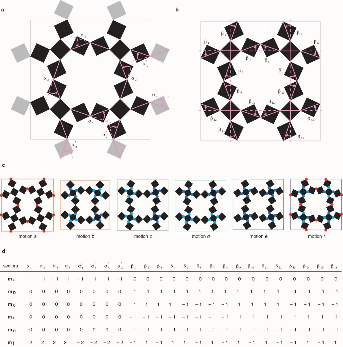
Motions: To focus on the essential physics, we define a system consisting of four unit cells, organized in a super-cell placed in a uniformly compressed square box with periodic boundary conditions. In a general system, periodic boundaries tie the nodes at the left (bottom) boundary to the nodes at the right (top) boundary, leading to constraints. To remain compatible with the experimental boundary conditions, we require that the super-cell fits in a square box: the edges at each side are required to be aligned, leading to an additional constraints, and the horizontal and vertical dimensions are required to be equal, leading to a single additional constraint. Hence, in the limit of flexible hinges, the number of zero modes with square periodic boundary conditions becomes:
| (2) |
For an , super-cell with square periodic boundary conditions we thus find six zero modes. We define a vector describing the bending of the links (See Extended Data Figure ED3(a-b)) and construct an appropriate orthogonal basis , which we refer to as motions (See Extended Data Figure ED3(c-d)). We choose motion and to coincide with the first step of pathways I (Fig. 1a) and II (Fig. 1b), and use the motions to characterize the soft modes and buckling modes.
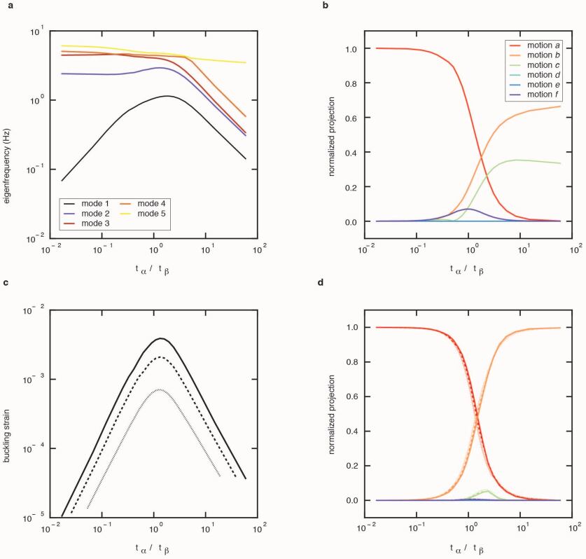
Linear Modes: We have calculated the softest eigenmodes at zero strain as function of and using a finite element method (See section ”Numerical simulations” below). We fix at 1, 2 and 3 mm and focus on the role of , as we find that the sum plays a very minor role for the mode structures. We find that for small values of , one mode is significantly softer than all others, while for larger values of , several modes are in close competition (Extended Data Figure ED4(a)). Consistent with our counting argument, this can be understood by noting that when , only motion is soft, whereas when , motions are all soft, with the eigenmodes mixing these motions.
By characterizing the spatial structure of the softest mode by projecting it onto the motions , we obtain the following scenario. First, there is a broad crossover regime where multiple motions are important, with the crossover centered around , consistent with the fact that there are more -links than -links. Second, for small values of , motion dominates, while at large values of , motion and both play a role (Extended Data Figure ED4(b)). Together, this analysis suggests that for sufficiently small , where the lowest mode is well isolated and closely corresponds to motion , pathway I can be robustly obtained, whereas the situation for large is more complex, with multiple modes and motions in competition.
Buckling Modes: To fully understand the role of , we have performed a stepwise nonlinear analysis and calculated the critical strain at which the first mode becomes unstable, and similarly project the corresponding nonlinear buckling mode onto the six motions (Extended Data Figure ED4(c-d)). This data confirms the picture of a crossover at . We note that the buckling modes can almost completely be expressed as a combination of motion and , with other motions suppressed and essentially irrelevant.
I.5 Symmetry broken links
Execution of pathway II is more difficult than pathway I presumably because of the large number of competing modes and motions with deformations of the -links. However, it is possible to select pathway II, even for moderate values of the thickness ratio , by introducing a symmetry breaking lateral offset in the -links. We fix the offset magnitude of this additional design parameter at (so the symmetry breaking is either on or off) and focus on offset patterns consistent with motion . We then run full nonlinear simulations on a super cell with square periodic boundary conditions for a range of values of the ratio while fixing mm. To illustrate the general scenario, we show snapshots of the undeformed and deformed system for and in Extended Data Figure ED5 (a-b). In both cases there is no instability and the deformation is smooth. At large strains we observe the deformed state corresponding to motion for , illustrating that motion is favoured for small even in the presence of offsets that promote motion . However, for larger the large strain deformation corresponds to motion , illustrating that a combination of symmetry breaking offsets and large allows to initiate pathway II (Extended Data Figure ED5(c-d)).
I.6 Design guidelines and experimental validation
We now turn our numerical observations on the crossovers between different behaviours as function of , with and without offsets, into practical design guidelines, noting that there are no sharp boundaries. First, we expect that pathway I should be observed without offsets whenever , with increasing fidelity for smaller ratio’s - for example, for , the overlap between the buckling mode and motion is more than 90% (Extended Data Figure ED4(d)). Second, to obtain pathway II, we suggest to combine an offset and large values of . For the specific offset magnitude used in this paper, , and an offset pattern of alternating chirality, i.e. concomitant with motion , our data shows that for , motion dominates; for example, for , the overlap between the nonlinear mode and motion is already 75% (Extended Data Figure ED5(c-d)). Finally we note that, experimentally, link thicknesses significantly less than 1 mm are not feasible, and link thicknesses larger than a few mm become comparable with the size of the square elements, thus providing practical constraints on our design space.
Experimental Validation Pathway I: We have performed experiments without offset, and with (shown in Fig. 2a-d), and (not shown) that both show a clear Pathway I, as well as with that shows a disordered Pathway (not shown). Moreover, earlier experiments with less accurately manufactured 3D printed samples also showed clear Pathway I deformations—Pathway I is robust for . In addition, we have performed experiments with an offset pattern of constant chirality, i.e. consistent with motion , for and ; the former two lead to smoothed versions of pathway I, the latter three to disordered pathways (Fig. 2).
Experimental Validation Pathway II: We have attempted to experimentally obtain pathway II without offset and . Despite the fact that a large part of the sample follows motion these samples also display a significant amount of disorder, seemingly nucleating near the boundaries, that prevent a successful execution of pathway II (Extended Data Figure ED6). We therefore have performed experiments with an offset with an alternating chirality consistent with motion (Fig. 2). We find that pathway II can be obtained for a moderate value of (not shown) and (Fig. 2).
I.7 Numerical simulations
For the finite elements simulations of a representative metamaterial element we use the commercial software Abaqus/Standard.
Model definition. We model super cells of our metamaterials varying the parameters , and the offset (Extended Data Figure ED7) using a neo-Hookean energy density as a material model, using a shear modulus, G = MPa and bulk modulus, K = GPa (or equivalently a Young’s modulus E = MPa and Poisson’s ratio ) in plane stress conditions with hybrid quadratic triangular elements (Abaqus type CPS6). We construct the mesh such that the thinnest parts of the samples with at least two elements across. As a result, the metamaterial unit cells have approximately triangular elements.
Boundary conditions. To implement periodic square boundary conditions, we define constraints on the displacements of all the nodes at the horizontal and vertical boundaries of the unit cell 31. In addition, we ensure that the periodic boundary condition remain square-shaped.
We perform three types of analysis:
Linear eigenmodes analysis: We calculate the lowest eigenmodes and their eigenfrequencies (Extended Data Figure ED4 (a-b)).
Nonlinear bifurcation analysis:
We perform a stepwise nonlinear stability analysis to determine the bifurcation point with a relative accuracy of (Extended Data Figure ED4 (c-d)).
Nonlinear compression using imperfection:
To study metamaterials whose -links have an offset , we compress the structure up to a strain (Extended Data Figure ED5).
I.8 Experimental techniques
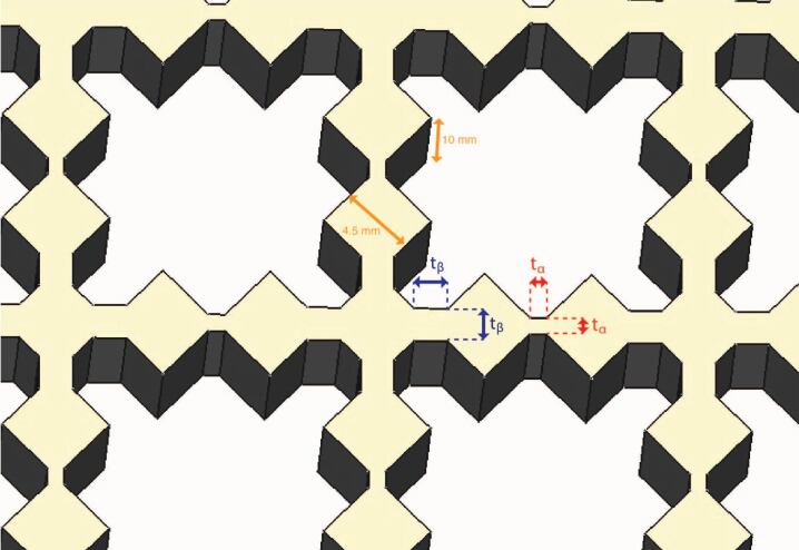
We used 10 mm-thick cast sheets of silicone rubber (shore 80A, Silex Silicones LTD, Young’s modulus MPa), that is sufficiently stiff to ensure minimal affection by gravity, and exhibits minimal viscous and creeping effects. We fabricated the samples using a waterjet cutter, gluing the rubber to 10 mm thick plywood boards to ensure precise cutting. We then marked each internal square (side mm) of the sample with an ellipse ( mm mm) for detection purposes.
The hinges between each square consist of rectangular cuboid beams of height mm (same at the sheet thickness) and of lateral thickness , or . We note that, irrespective of the beams, the (virtual) corners of the squares precisely meet in a point — the beams add material to this idealized design (Fig.ED7). The thicknesses of , , range from mm to mm, depending on the nature of the link (, or ) and on the sample (see main text and Methods for specifications). In some runs, we laterally offset the beams by , leading to triangular shaped links. The rank II (rank III) metamaterials shown in Figs. 1,2 (Fig. 3) consist of () unit cells, namely () internal squares.
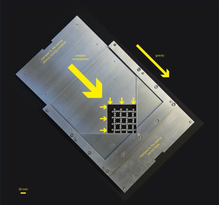
The samples were tested under equi-biaxial compression. To this end, we used a custom made aluminium V-shaped press (See Extended Data Fig. ED8) that was carefully positioned and aligned in a universal testing machine (Instron 3366) equipped with a N load cell, thus allowing to impose a compressive displacement within a m accuracy and to record the force within a N accuracy. We used fine powder to reduce the friction at the boundaries as much as possible.
The pictures were recorded using a high-resolution CMOS camera ( px px, Basler acA3800-14um) equipped with a 75 mm (50 mm) prime lens (KOWA, LM50HC 1” and LM75HC 1”, respectively) for the rank two (rank three) metamaterials paired with custom made LED-based front and back light systems. In order to minimise reflections from the front light, the V-press glass windows are coated against reflections.
I.9 Image tessellation techniques
The images were processed through standard image tessellation and tracking techniques to extract the positions of the squares as well as the bending angles of the links connecting the squares. In particular, through a semi-automatic custom-made tracking algorithm, special attention was devoted to obtain space-time trajectories of nearly all squares and bending angles (See Supplementary Videos). Inevitable detection errors occurred close to the edges of the compression cell or when squares come in contact and led to flickering of the square positions and orientation and therefore of the measurement of the bending angles. To tackle this issue, events where the angles fluctuates more than between two consecutive frames have been filtered out. We verified that the value of the filtering threshold has a minor effect on the data only.
In addition, as discussed in the main text, friction and frustration at the boundary inevitably cause distortions and misfoldings, whose description goes beyond the scope of this work. Therefore, in order to compute the bending angles shown in Figs. 2d,h,l,p (Fig. 3), we restrict our attention to a region of interest comprising the 28 (29) most central squares for the rank II (rank three) metamaterial. In Fig. ED9 we show the same data, now calculated over a much wider area, comprising 64 (respectively 165 squares)—even though the scatter is larger, the main trends and multi-step nature are also apparent in this data.
I.10 Sequential pathways with alternative topologies
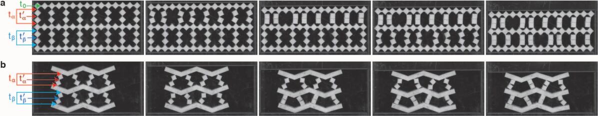
To demonstrate that sequential pathways are not limited to the hierarchical structures under biaxial compression shown in the main text, we have constructed two alternative geometries that show a two-step pathway under uniaxial compression, using the same rubber and water-jetting technique as for the samples shown in the main text (see Extended Data Figure ED10). The basic idea is to couple two groups of links with different buckling thresholds in series, so that under compression these two types of links buckle in sequence. In one geometry, we use a diluted square lattice consisting of two rows of coupled columns with different link thicknesses (Extended Data Figure ED10(a)). Under compression, we observe that the columns with the thinnest links buckle first, then fold up until self-contacts are created, and then trigger the buckling of the other columns with thicker links. We note that as this structure is soft to lateral shear, we use lateral sliding boundaries. In the second geometry, we use a variation that removes the soft shear modes, so that no lateral boundaries are required; also here, a clear two-step sequence is observed (Extended Data Figure ED10(b)). These alternative designs demonstrate that the combination of buckling and self contacts can generate sequential pathways in a variety of structures.
Data and code availability. The data and codes that support the plots within this paper and other findings of this study are available from the corresponding author upon request.
II Extended Data