Date of publication xxxx 00, 0000, date of current version xxxx 00, 0000. 10.1109/ACCESS.2019.2925680.DOI
This work was partially supported by KAUST-KSU Special Initiative (KKI2) Program, REP/1/3803-01-01.
Corresponding author: El-Mehdi Amhoud (e-mail: mehdi.amhoud@kaust.edu.sa).
OAM Mode Selection and Space-Time Coding for Atmospheric Turbulence Mitigation in FSO Communication
Abstract
Orbital angular momentum (OAM) multiplexing has recently received considerable interest in free space optical (FSO) communications. Propagating OAM modes through free space may be subject to atmospheric turbulence (AT) distortions that cause intermodal crosstalk and power disparities between OAM modes. In this article, we are interested in multiple-input multiple-output (MIMO) coherent FSO communication systems using OAM. We propose a selection criterion for OAM modes to minimize the impact of AT. To further improve the obtained performance, we propose a space-time (ST) coding scheme at the transmitter. Through numerical simulations of the error probability, we show that the penalty from AT is completely absorbed for the weak AT regime and considerable coding gains are obtained in the strong AT regime.
Index Terms:
Orbital angular momentum (OAM), atmospheric turbulence, mode selection, space-time coding.=-15pt
I Introduction
In analogy to mode division multiplexing (MDM) in optical fibers where several spatial modes are used for multiplexing, orbital angular momentum (OAM) multiplexing is proposed as a versatile technique to transmit multiple signals over free space channels [1, 2]. OAM modes are orthogonal which makes them suitable to co-propagate and carry independent data streams in free space. Laboratory demonstrations have shown beyond 1 Pbit/s free space transmission with a spectral efficiency exceeding 100 bit/s/Hz using 26 modes [3]. However, in real-life communication scenarios, OAM beams are subject to atmospheric turbulence (AT) in which the refractive index of the air experiences spatial variations. The propagation of OAM beams in the turbulent atmosphere leads to phase-front distortions as well as beam spread and wandering. Moreover, the power of a signal carried by a particular OAM mode is spread to other modes which results in intermodal crosstalk. Furthermore, different OAM modes suffer from different channel losses known as mode-dependent loss (MDL) that causes performance degradation at the system level [4].
The mitigation of the effects of atmospheric turbulence can be done either at the beam level using adaptive optics (AO) compensation, or by using digital signal processing (DSP) techniques such as channel coding or equalization. AO aims at correcting the deformations of an incoming wavefront by deforming a mirror, or by controlling a liquid crystal array in order to compensate for aberrations. In [5, 6], a real-time AO compensation with wavefront sensors was used to correct the phase distortions. AO can be also used without wavefront sensors as in [7]. For DSP approaches,
MIMO equalization associated with heterodyne detection was shown to mitigate turbulence-induced crosstalk for 4-OAM beams carrying 20 Gbit/s QPSK signals in [8]. Also, pre-channel combining phase patterns allowed to reduce the crosstalk by 18-dB for a 2-OAM modes transmission in [9].
Moreover, coding techniques such as channel coding [7] and coded modulation [10] were also proposed to mitigate atmospheric turbulence in OAM FSO transmissions. Furthermore, In [11], the authors proposed a half-rate Alamouti space-time (ST) code and a vertical Bell labs layered ST (V-BLAST) code along with a sub-optimal zero-forcing channel equalization. The previously proposed AO and DSP solutions were shown to significantly improve the bit-error rate (BER) in the presence of AT. Nonetheless, in all the previous studies, MDL was not taken into consideration. Though even after compensation OAM modes still have different performances.
In the present contribution, we focus on the effect of MDL caused by atmospheric turbulence. We show that the amount of MDL depends on the OAM modes considered for multiplexing. Therefore, the BER can be improved by selecting the OAM modes that minimize the MDL. At the receiver, a maximum likelihood (ML) detection is used for optimal decoding performance. The proposed selection method completely absorbs the signal to noise ratio (SNR) penalty in weak turbulence conditions. For the strong turbulence regime, and in order to further enhance the obtained performance, full-rate full-diversity ST coding at the transmitter is proposed and the performance is evaluated for higher MIMO dimensions. The ST coding scheme brings more than 2.4 dB gain.
This article is organized as follows: In section II, spatial multiplexing using OAM in free space transmission and the atmospheric turbulence effect are described. In Section III, the OAM MIMO communication system model is presented. In Section IV, the mode selection strategy is proposed, and the achieved error probability performance is presented. In Section V, a space-time coding scheme is added at the transmitter to further enhance the obtained performance. In Section VI, we conclude and set forth future work perspectives.
II Orbital Angular Momentum Multiplexing
A lightwave carrying an OAM of is a wave having a helical phase-front induced by an azimuthally varying phase term , where is the topological charge, is the azimuth and is the reduced Planck constant. ‘Orbital’ angular momentum should not be confused with ‘spin’ angular momentum which is related to circular polarization and could have two possible states ‘right-handed’ and ‘left-handed’ circularly polarized. To realize OAM multiplexing, single and superpositions of orthogonal beams that have a well-defined vorticity can be used including Hermite-Gaussian (HG) beams [12], Ince-Gaussian beams [13], Bessel-Gaussian beams [14], and Laguerre-Gauss (LG) beams [15]. Here, we consider OAM carrying beams derived from LG modes. The field distribution of the LG beams is given by [16]:
| (1) |
where refers to the radial distance, is the azimuth angle, is the propagation distance. is the beam radius at the distance , where is the beam waist of the Gaussian beam, is the Rayleigh range, and is the optical wavelength carrier [16]. is the wavenumber. is the generalized Laguerre polynomial, where and represent the radial and angular mode numbers. OAM modes correspond to the subset of LG modes having and which makes OAM multiplexing not optimal fo achieving the capacity limits of FSO communication systems [17, 18].
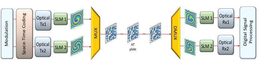
A representation of a MIMO OAM FSO transmission system is shown in Fig. 1.
Generation of OAM beams in practice can be realized thanks to different techniques including spiral phase plates (SPP) [19], q-plates [20], metamaterials [21], computer-generated holograms (CGHs) loaded on spatial light modulators (SLMs) [22], and integrated compact devices [23]. An SPP is an optical element having the form of spiral staircases that shapes an incident Gaussian beam into a twisted beam having a helical phase-front. A single SPP allows the generation of a unique OAM mode with a particular topological charge in a stable and efficient manner for a particular wavelength which similar to q-plates that is usually made with liquid crystals with strong wavelength dependence. Metamaterials-based devices and integrated devices are still limited to a low number of OAM modes. However, an SLM can be dynamically addressed to change a digital hologram displayed on a liquid crystal display (LCD) to generate single and superposition of OAM beams in a wide wavelength range from a Gaussian incident beam. SLMs are the most commonly used devices in communication experiments involving OAM beams in different wavelength ranges. At the receiver side, the inverse operation can be performed using the same device to transform an incoming OAM mode back to a Gaussian beam. The idea is to apply an optical scalar product measurement between the incident OAM beam and a CGH with the conjugate phase at the image plane of a Fourier transforming lens [24]. The only inconvenience of using such devices is the diffraction losses at the transmission and reception due to the efficiency of the LCD. The produced Gaussian beam can then be injected into a photodetector to recover the originally encoded signal.
The vorticity of OAM beams propagating in a FSO media without atmospheric turbulence is preserved and OAM beams maintain orthogonality as they propagate which can be described by:
| (2) |
where refers to the normalized field distribution of OAM mode of order at distance and refers to the radial position vector.
OAM Propagation in Turbulence
The propagation of OAM modes can be affected by atmospheric turbulence induced distortions [4, 5, 8, 11]. Atmospheric turbulence is caused by pressure and temperature fluctuations in the atmosphere which results in a random behavior of the atmospheric refractive index. Due to AT, the power of an initially transmitted OAM mode leaks to other modes including the ones unused for multiplexing. This phenomenon causes signal overlapping as well as power disparities between OAM modes.
To emulate atmospheric turbulence, random phase screens are placed along the FSO channel (see Fig. 1). These phase screens are generated based on the modified version of the Kolmogorov spectrum given by [25]:
| (3) |
where . is the refractive index structure parameter, is the outer scale of the turbulence, , with is the inner scale of the turbulence. The turbulence strength in an FSO channel is given by the Rytov variance defined as , where is the carrier wavelength and is the propagation distance. We note that for (), the system is operating under a weak (strong) turbulence regime. The beam waist at the transmitter for all beams is set to cm to ensure a minimal beam waist at the receiver plane. On the other hand, we assume that the optical receiver is large enough to collect all received OAM beams. To create the desired OAM modes, SLMs with LCD of dimension pixels are used. The propagation distance is set to km, the inner and outer scales of turbulence are set to mm and m, respectively. AT is emulated by placing random phase screens each m. Each phase screen is evaluated as the Fourier transform of a complex random distribution with zero mean and variance equal to , where is the array length and mm is the grid spacing assumed to be equal in both dimensions and . Propagation through the turbulent atmosphere is simulated using the commonly used split-step Fourier method at wavelength nm. For weak (strong) turbulence, we set (), respectively.
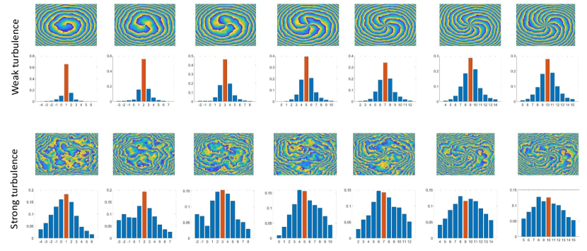
The phase-front of OAM beams with topological charges and their corresponding mode purity graphs are presented in Fig. 2 for different atmospheric turbulence regimes after 1 km of propagation. For the weak turbulence regime, the phase-front of OAM modes is affected but can still be recognizable. In this case, the spread of optical power to other OAM modes is relatively low (blue bars) and more power is conserved in the originally launched mode (red bars). However, for a strong turbulence regime, we can clearly see that the phase of OAM beams is severely impacted. This results in a wide spread and a considerable power leakage to other OAM modes. Moreover, we also notice that due to beam spread, OAM modes with higher topological charges suffer from more important power spread (see mode purity graphs in Fig. 2) which impacts the OAM capacity and system outage as shown in [26].
In addition to crosstalk, the break of the orthogonality between OAM states due to AT causes transmitted modes to have different losses. MDL creates an SNR imbalance of the received signals, and since the overall system performance is averaged over all received signals, then the performance is limited by the signal with the most degraded SNR.
MDL was intensively studied for few-mode fibers, and multi-core fibers optical communications [27, 28, 29] and was shown to be the main performance limiting factor. In OAM FSO communications, the impact of MDL was only investigated in the case of laterally displaced OAM beams [12].
In the next section, we show that MDL also reduces the performance of OAM FSO systems. Moreover, the selected OAM modes for multiplexing determines the level of MDL of the MIMO system.
III System Model
The transmission of OAM beams in the turbulent FSO channel can be described by an MIMO system as:
| (4) |
where is a vector of modulated symbols. is the received symbols vector. denotes the noise assumed to be additive white Gaussian with variance per complex dimension. The transmission matrix is a square matrix of dimension . It represents the turbulent FSO channel, where each diagonal element is the efficiency of channel which represents the amount of power that remains in OAM state . The crosstalk between OAM states due to turbulence is represented by the channel inputs and can be expressed as follows:
| (5) |
The crosstalk fading was demonstrated in [30] to obey a Johnson distribution. However, the latter distribution is analytically intractable which makes theoretical derivations not feasible. After propagating through the turbulent atmosphere, symbols carried by OAM beams are subject to transmission errors. To retrieve the original signals, at the receiver side, we can estimate the symbols using a maximum likelihood (ML) decoder. The latter gives the optimal decoding performance and hence, can be considered as a powerful DSP technique to recover signals after being distorted by AT [31]. The ML criterion estimates the transmitted symbols vector by minimizing the following Euclidean distance:
| (6) |
where is the estimated symbols vector and is the set of all possible symbols. The ML detection can be realized by an exhaustive search over all combination possibilities in the set . However, it is often considered not to be feasible in practice due to the exponential computational complexity that scales with , where is the constellation size. To overcome this issue, reduced search lattice decoders can also return the ML solution at a reduced complexity. By applying a complex to real transformation to Eq. (4), the ML decoding metric can be rewritten as:
| (7) |
Consequently, the problem of minimizing the quadratic error becomes a search problem for the closest point in the lattice generated by the equivalent real matrix .
In our work, we consider the sphere decoder (SD) [32] for decoding the received signals. The SD searches for the optimal point in a finite sphere centered on the received point . Consequently, the complexity is reduced, and more importantly becomes independent from the constellation size and is approximately equal to [33].
The error probability of the transmission is given by [34, chap. 4]:
| (8) |
where the sum is over all possible transmitted symbol vectors .
IV OAM Mode Selection
Mode-dependent loss is given by the decibel ratio of the maximum to the minimum eigenvalues of the channel matrix as [28, 29]:
| (9) |
where (resp. ) is the maximum (resp. minimum) eigenvalue of the channel matrix.
Let be the set of available OAM modes for multiplexing, we aim to select the set of OAM modes that gives the best performance in terms of the error probability.
In [26], the authors found the set of OAM modes that maximizes the asymptotic average transmission rate when all OAM modes were considered as independent channels in an IM/DD system. However, maximizing the overall channel capacity does not guarantee the optimal reliability performance of the system. Hence, different BERs are observed for each OAM mode which impacts the average BER of the system. In this work, a joint detection of all OAM modes based on ML decoding is considered. In the presence of modal crosstalk only and without MDL, the ML decoder is capable of uncoupling all channels and achieves the same BER performance as a crosstalk-free transmission. However, in the presence of MDL, the performance of the ML decoder degrades. Consequently, to obtain the optimal BER performance, we focus on minimizing the MDL of the MIMO channel.
Moreover, the MDL of the channel does not depend on the SNR but only depends on the power ratio between the maximum and minimum received powers. Hence, we aim to find the optimal set of modes that satisfies the following condition:
| (10) |
where spans all the possible subsets of .
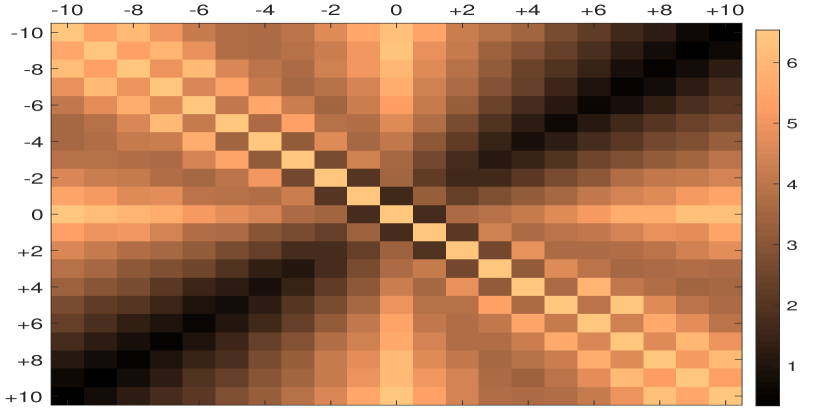
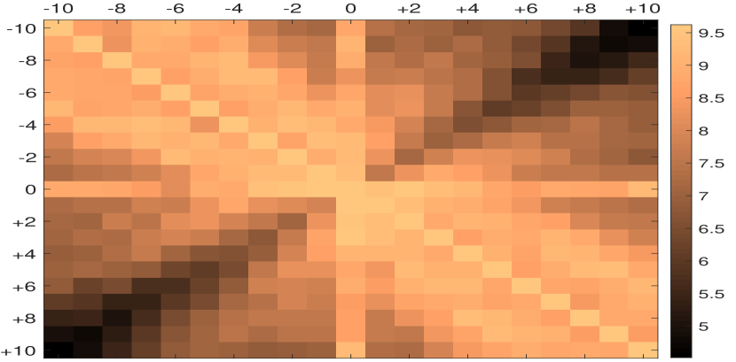
To have an insight on the MDL levels for different sets of OAM modes, we consider a MIMO transmission. We compute the MDL averaged over channel realizations by considering the same simulation parameters of the previous section.
In Fig. 3(a) and 3(b), the MDL is shown for all possible combinations of OAM modes with topological charges and spanning the set . For both the weak and strong AT regimes, the minimum values of the MDL were found for OAM modes having opposite topological charges () (see anti-diagonal elements in Fig. 3). Moreover, for OAM modes satisfying the previous condition, the MDL decreases as the topological charge increases. Hence, the lowest MDL corresponds to the set . Another important observation is that a pair of modes with a low level of crosstalk does not necessarily achieve a low level of MDL. For example the set have more crosstalk than because OAM mode will spread more power to than to which is much further. Nonetheless, the MDL of the set is lower than the set .
Furthermore, we have resolved the minimization problem of Eq. (10) and found the optimal sets of OAM modes that minimize MDL for higher MIMO dimensions. In Table I, the optimal sets are given for different AT strengths given by the values of the refractive index structure parameter. As shown from the table, further OAM modes having opposite topological charges allow obtaining the lowest MDL.
| MIMO | Refractive index structure parameter | Optimal OAM set |
|---|---|---|
To examine the efficiency of the proposed mode selection approach on the error probability performance, we consider the transmission of OAM modes in a and MIMO configurations.
At the transmitter, bits are modulated to form QPSK symbols that are sent on the propagating modes. At the receiver, a sphere decoder is implemented. We measure the BER performance using Monte-Carlo simulations, and for each simulated point, we record a minimum of 100 bit errors.
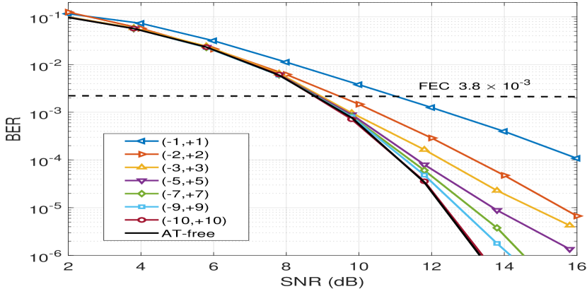
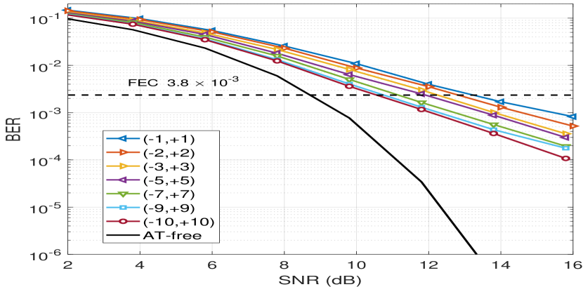
In Fig. 4, we consider a MIMO system, we plot the BER as a function of SNR for different sets of OAMs in the weak and strong turbulence regimes. The atmospheric turbulence-free case using the Gaussian beam is also plotted as a reference. From Figs. 4(a) and 4(b), we notice that as the topological charge increases the BER decreases and the optimal performance is reached for the set . For weak atmospheric turbulence, (as depicted in Fig. 4(a)), excepting the set , all other sets of OAM modes reached the same performance as the AT-free channel at the forward error correction (FEC) limit of . These results, clearly show that the choice of the OAM modes based on the minimization of the MDL is an accurate criterion to obtain the lowest error probability performance. However, as can be seen from Fig. 4(b), in the strong turbulence regime, the optimal OAM set could not completely compensate for AT.
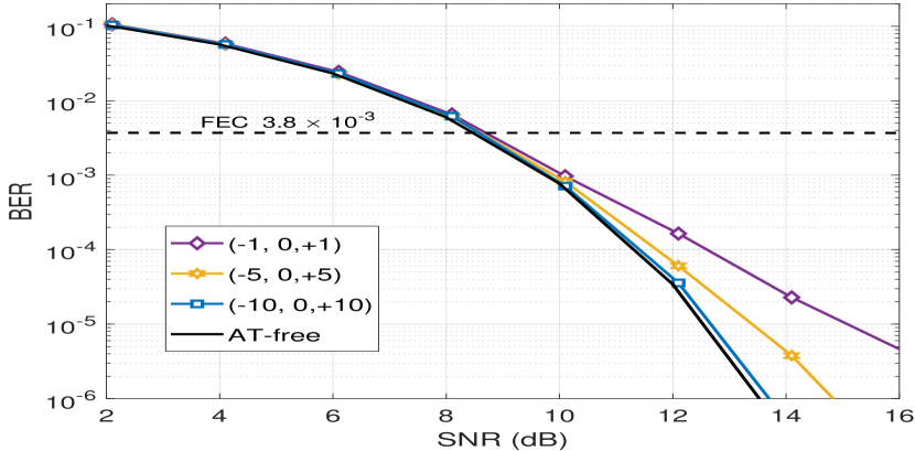
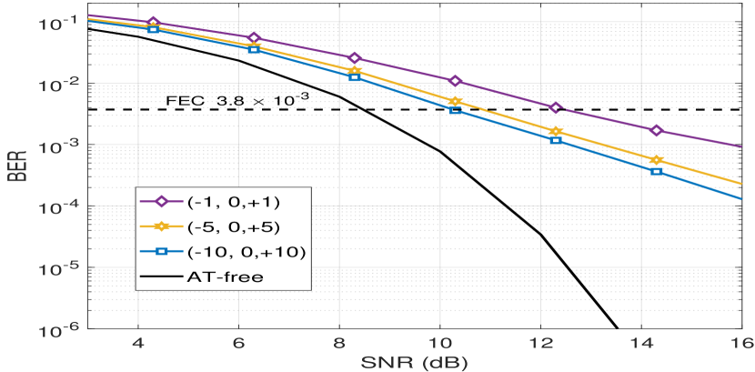
In Fig. 5, we consider a MIMO system. For both the weak and strong AT regimes, we notice that the lowest BER is achieved by the OAM set . For the weak turbulence regime (as depicted in Fig. 5(a)) the latter set of modes achieves the performance of the AT-free channel at BER below the FEC limit. For strong atmospheric turbulence (see Fig. 5(b)) the optimal set of OAM modes also achieves the lowest BER. Nonetheless, the performance degrades significantly due to the severity of the turbulence. To further enhance, the obtained performance, we propose to add a space-time coding scheme at the transmitter.
V Space-Time Coding
Space-time coding was initially designed for MIMO wireless communication to bring coding gain and achieve a full-diversity at the transmitter side in a constantly varying channel. Recently, ST coding was also investigated for optical communication and was demonstrated to be efficient in mitigating non-unitary effects in polarization multiplexed systems [35] and also in few-mode fibers [27, 28]. The ST coding principle consists in transmitting a coded linear combination of modulated signals during several channel uses. At the receiver side, the ML detector estimates the data from the different copies present on all modes which allows giving a better estimate. Different ST code families have been designed for wireless MIMO channels such as ST block codes (STBC) [36], and ST trellis codes (STTC) [37]. We particularly focus here on the STBC.
For a MIMO channel, and during two channel uses, a ST codeword matrix uses 4 modulated symbols to achieve a full-rate transmission. In our analysis, we use the Golden code [38] and the Silver code [39] which are known to be the two best ST codes satisfying a full-rate, full-diversity and optimal coding gain.
In addition to a full-rate and full-diversity, the Golden code [38] achieves the best coding gain for Rayleigh fading channels given by its minimum determinant equal to . The design of the Golden code is based on the Golden number used for the code construction. The codeword matrix is given by:
| (11) |
where , , , , and are the modulated QPSK symbols.
The Silver code has also a full-rate and full-diversity for MIMO Rayleigh fading channels. Its minimum determinant is equal to , which explains the slightly lower performance than the Golden code. However, the Silver code has a reduced decoding complexity [40].
The Silver codeword matrix is given by:
| (12) | ||||
| (13) |
with and are given by:
Furthermore, for the MIMO system, we consider a threaded algebraic ST code (TAST) [41]. The main advantage of the TAST code family is that it can achieve a full-rate and full-diversity for any MIMO scheme [41]. The TAST codeword matrix for a MIMO channel is given by Eq. (14).
| (14) |
where , , and are QPSK symbols.
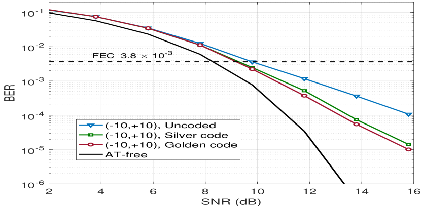
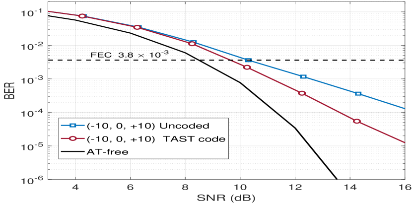
To have an insight on the performance of ST coding on OAM FSO transmission over a turbulent channel, we compare ST coded transmissions using the Golden and Silver codes to the uncoded transmission. A QPSK constellation is used to construct the codewords of the ST codes. We measure the BER performance using Monte-Carlo simulations, and for each simulated point, we record a minimum of 100 bit errors. In Fig. 6(a), we plot the BER curves versus the SNR for the strong AT regime for a MIMO system using the OAM set . From the figure, we notice that the ST coded scheme provides an important coding gain compared to the uncoded transmission. The Golden code outperforms the Silver code, and the coding gain obtained at BER= by the Golden code is 2.2 dB compared to the uncoded scheme. Hence the SNR gap to the turbulence-free channel is reduced to 2.6 dB. In Fig. 6(b), we consider a MIMO system using the OAM set in the strong atmospheric turbulence regime. From the figure, we notice that at a BER= the TAST code provides 2.2 dB gain compared to the uncoded scheme. Consequently, the obtained results, show that ST coding is an efficient DSP coding technique capable of mitigating atmospheric turbulence in OAM FSO systems.
VI Conclusion
In summary, we have shown that an optimal selection of OAM modes is relevant to improve the performance of OAM FSO systems over the turbulent atmosphere. The selection criterion is based on the minimization of the MDL without any algorithm required to update the set of optimal OAM modes. Hence, it is a low-cost complexity solution that can be integrated into real-time systems. In our simulations, we have considered an ML decoding strategy to obtain optimal performances. Nonetheless, sub-optimal decoders with lower complexity can be also used. To further mitigate the atmospheric turbulence effect on FSO transmission, we proposed a ST coding scheme at the transmitter. We showed that AT was completely mitigated in the weak turbulence regime and important coding gains were obtained in the strong turbulence regime. Future work will extend to experimental validation of the proposed techniques. The use of OAM modes with non-null radial index will be equally considered.
References
- [1] G. Gibson et al. “Free-space information transfer using light beams carrying orbital angular momentum” In Optics express 12.22 Optical Society of America, 2004, pp. 5448–5456
- [2] A. Trichili et al. “Communicating Using Spatial Mode Multiplexing: Potentials, Challenges and Perspectives” In accepted for publication in IEEE Communications Surveys & Tutorials, 2019
- [3] J. Wang et al. “N-dimentional multiplexing link with 1.036-Pbit/s transmission capacity and 112.6-bit/s/Hz spectral efficiency using OFDM-8QAM signals over 368 WDM pol-muxed 26 OAM modes” In European Conference on Optical Communication (ECOC), 2014, pp. 1–3
- [4] Y. Ren et al. “Atmospheric turbulence mitigation in an OAM-based MIMO free-space optical link using spatial diversity combined with MIMO equalization” In Optics Letters 41.11 Optical Society of America, 2016, pp. 2406–2409
- [5] M. Li, M. Cvijetic, Y. Takashima and Z. Yu “Evaluation of channel capacities of OAM-based FSO link with real-time wavefront correction by adaptive optics” In Optics express 22.25 Optical Society of America, 2014, pp. 31337–31346
- [6] Y. Ren et al. “Adaptive-optics-based simultaneous pre-and post-turbulence compensation of multiple orbital-angular-momentum beams in a bidirectional free-space optical link” In Optica 1.6, 2014, pp. 376–382
- [7] Z. Qu and I. B. Djordjevic “500 Gb/s free-space optical transmission over strong atmospheric turbulence channels” In Optics letters 41.14 Optical Society of America, 2016, pp. 3285–3288
- [8] H. Huang et al. “Crosstalk mitigation in a free-space orbital angular momentum multiplexed communication link using 44 MIMO equalization” In Optics Letters 39.15 Optical Society of America, 2014, pp. 4360–4363
- [9] H. Song et al. “Experimental Mitigation of Atmospheric Turbulence Effect using Pre-Channel Combining Phase Patterns for Uni-and Bidirectional Free-Space Optical Links with Two 100-Gbit/s OAM-Multiplexed Channels” In Optical Fiber Communication Conference, 2019, pp. Th4C–4 Optical Society of America
- [10] Z. Qu and I. B. Djordjevic “Two-stage cross-talk mitigation in an orbital-angular-momentum-based free-space optical communication system” In Optics letters 42.16, 2017, pp. 3125–3128
- [11] Y. Zhang et al. “Performance analysis of an OAM multiplexing-based MIMO FSO system over atmospheric turbulence using space-time coding with channel estimation” In Optics Express 25.17 Optical Society of America, 2017, pp. 19995–20011
- [12] B. Ndagano, N. Mphuthi, G. Milione and A. Forbes “Comparing mode-crosstalk and mode-dependent loss of laterally displaced orbital angular momentum and Hermite–Gaussian modes for free-space optical communication” In Optics Letters 42.20 Optical Society of America, 2017, pp. 4175–4178
- [13] M. A Bandres and J. C. Gutiérrez-Vega “Ince–Gaussian beams” In Optics letters 29.2, 2004, pp. 144–146
- [14] F. Gori, G. Guattari and C. Padovani “Bessel-gauss beams” In Optics communications 64.6, 1987, pp. 491–495
- [15] L. Allen, M. W Beijersbergen, R. Spreeuw and J. P. Woerdman “Orbital angular momentum of light and the transformation of Laguerre-Gaussian laser modes” In Physical Review A 45.11 APS, 1992, pp. 8185
- [16] T. Doster and A. T. Watnik “Laguerre–Gauss and Bessel–Gauss beams propagation through turbulence: Analysis of channel efficiency” In Applied Optics 55.36 Optical Society of America, 2016, pp. 10239–10246
- [17] N. Zhao, X. Li, G. Li and J. M. Kahn “Capacity limits of spatially multiplexed free-space communication” In Nature photonics 9.12, 2015, pp. 822
- [18] M. Chen, K. Dholakia and M. Mazilu “Is there an optimal basis to maximise optical information transfer?” In Scientific reports 6, 2016, pp. 22821
- [19] M.W. Beijersbergen, R.P.C. Coerwinkel, M. Kristensen and J.P. Woerdman “Helical-wavefront laser beams produced with a spiral phaseplate” In Optics Communications 112.5-6, 1994, pp. 321–327
- [20] L. Marrucci, C. Manzo and D. Paparo “Optical spin-to-orbital angular momentum conversion in inhomogeneous anisotropic media” In Physical Review Letters 96.16, 2006, pp. 163905
- [21] Z. Zhao, J. Wang, S. Li and A. E. Willner “Metamaterials-based broadband generation of orbital angular momentum carrying vector beams” In Optics letters 38.6, 2013, pp. 932–934
- [22] N.R. Heckenberg, R. McDuff, C.P. Smith and A.G. White “Generation of optical phase singularities by computer-generated holograms” In Optics Letters 17.3, 1992, pp. 221–223
- [23] Xinlun Cai et al. “Integrated compact optical vortex beam emitters” In Science 338.6105, 2012, pp. 363–366
- [24] I. A. Litvin, A. Dudley, F. S. Roux and A. Forbes “Azimuthal decomposition with digital holograms” In Optics Express 20.10 Optical Society of America, 2012, pp. 10996–11004
- [25] L C. Andrews “An analytical model for the refractive index power spectrum and its application to optical scintillations in the atmosphere” In Journal of Modern Optics 39.9 Taylor & Francis, 1992, pp. 1849–1853
- [26] S. Huang, G. R. Mehrpoor and M. Safari “Spatial-mode diversity and multiplexing for FSO communication with direct detection” In IEEE Transactions on Communications 66.5 IEEE, 2018, pp. 2079–2092
- [27] E-M. Amhoud et al. “Experimental Demonstration of Space-Time Coding for MDL Mitigation in Few-Mode Fiber Transmission Systems” In IEEE European Conference on Optical Communication (ECOC), 2017, pp. 1–3
- [28] E. Awwad, G. Rekaya and Y Jaouen “Space-Time Coding Schemes for MDL-Impaired Mode-Multiplexed Fiber Transmission Systems” In Journal of Lightwave Technology 33.24, 2013, pp. 5084–5094
- [29] P. J. Winzer and G. J. Foschini “MIMO capacities and outage probabilities in spatially multiplexed optical transport systems” In Optics Express 19.17 Optical Society of America, 2011, pp. 16680–16696
- [30] G. Funes, M. Vial and J. A. Anguita “Orbital-angular-momentum crosstalk and temporal fading in a terrestrial laser link using single-mode fiber coupling” In Optics Express 23.18 Optical Society of America, 2015, pp. 23133–23142
- [31] B. Gupta and D. S. Saini “BER performance improvement in MIMO systems using various equalization techniques” In IEEE International Conference on Parallel, Distributed and Grid Computing, 2012, pp. 190–194 IEEE
- [32] E. Viterbo and J. Boutros “A universal lattice code decoder for fading channels” In IEEE Transactions on Information theory 45.5 IEEE, 1999, pp. 1639–1642
- [33] O. Damen, A. Chkeif and J.-C. Belfiore “Lattice code decoder for space-time codes” In IEEE Communications letters 4.5 IEEE, 2000, pp. 161–163
- [34] J. G. Proakis and M. Salehi “Digital Communications” McGraw-Hill, 2008
- [35] E. Awwad, Y. Jaouen and G. Rekaya “Polarization-time coding for PDL mitigation in long-haul PolMux OFDM systems” In Optics Express 21.19 Optical Society of America, 2013, pp. 22773–22790
- [36] A. F. Naguib, N. Seshadri and A. R. Calderbank “Applications of space-time block codes and interference suppression for high capacity and high data rate wireless systems” In Conference Record of Thirty-Second Asilomar Conference on Signals, Systems and Computers 2, 1998, pp. 1803–1810
- [37] V. Tarokh, N. Seshadri and A. R. Calderbank “Space-time codes for high data rate wireless communication: Performance criterion and code construction” In IEEE Transactions on Information Theory 44.2 IEEE, 1998, pp. 744–765
- [38] J.-C. Belfiore, G. Rekaya and E. Viterbo “The golden code: a 22 full-rate space-time code with non-vanishing determinants” In IEEE Transactions on Information Theory 51.4, 2005, pp. 5084–5094
- [39] O. Tirkkonen and A. Hottinen “Improved MIMO performance with non-orthogonal space-time block codes” In IEEE Global Telecommunications Conference 2, 2001, pp. 1122–1126
- [40] E. Biglieri, Y. Hong and E. Viterbo “On fast-decodable space–time block codes” In IEEE Transactions on Information Theory 55.2 IEEE, 2009, pp. 524–530
- [41] H. El Gamal and M. O. Damen “Universal space-time coding” In IEEE Transactions on Information Theory 49.5 IEEE, 2003, pp. 1097–1119