Supplementary Material to: Passive Controller Realization of a Biquadratic Impedance with Double Poles and Zeros as a Seven-Element Series-Parallel Network for Effective Mechanical Control
Abstract
This report presents some supplementary material to the paper entitled “Passive controller realization of a biquadratic impedance with double poles and zeros as a seven-element Series-parallel network for effective mechanical control” [1].
Keywords: Passive mechanical control, passive network synthesis, inerters, biquadratic impedances, series-parallel networks.
I Introduction
This report presents some supplementary material to the paper entitled “Passive controller realization of a biquadratic impedance with double poles and zeros as a seven-element Series-parallel network for effective mechanical control” [1], which are omitted from the paper for brevity.
II Preliminaries of Passive Network Synthesis
A two-terminal electrical network is defined to be passive if for all and for all admissible current and voltage [2]. A real-rational function is positive real if is analytic and for any [9]. An impedance (resp. admittance) is defined to be (resp. ), where and are voltages and currents of the port of a two-terminal network, where the network is said to realize (or is a realization of) its impedance (resp. admittance). A two-terminal electrical network is passive if and only if its impedance (resp. admittance) is positive real, and any positive-real impedance (resp. admittance) is realizable as a two-terminal passive network [9]. Any positive-real impedance (resp. admittance) is realizable as a two-terminal passive network. A reactive element is an inductor or capacitor, and a resistor is also called as a resistive element.
III Definitions of the network duality and the frequency inverse
Any two-terminal passive network can be regarded as a one-terminal-pair labeled graph with two distinguished terminal vertices (see [13, pg. 14]), in which the labels designate passive circuit elements regardless of element values, namely resistors, capacitors, and inductors, which are labeled as , , and , respectively.
Two natural maps acting on the labeled graph are defined as follows:
-
1.
Graph duality, which takes the one-terminal-pair graph into its dual (see [13, Definition 3-12]) while preserving the labeling.
-
2.
Inversion, which preserves the graph but interchanges the reactive elements, that is, capacitors to inductors and inductors to capacitors with their labels to and to .
Consequently, one defines
Consider a network whose one-terminal-pair labeled graph is . Denote as the network whose one-terminal-pair labeled graph is , resistors are of the same values as those of , and inductors (resp. capacitors) are replaced by capacitors (resp. inductors) with reciprocal values, which is called the frequency inverse network of . Denote as the network whose one-terminal-pair labeled graph is and elements are of the reciprocal values to those of , which is called the frequency inverse dual network of . Denote as the network whose one-terminal-pair labeled graph is , resistors are of reciprocal values to those of , and inductors (resp. capacitors) are replaced by capacitors (resp. inductors) with same values, which is called the dual network of .
It can be proved that (resp. ) is realizable as the impedance (resp. admittance) of a network whose one-terminal-pair labeled graph is , if and only if (resp. ) is realizable as the impedance (resp. admittance) of whose one-terminal-pair labeled graph is , if and only if (resp. ) is realizable as the admittance (resp. impedance) of whose one-terminal-pair labeled graph is , and if and only if it is realizable as the admittance (resp. impedance) of whose one-terminal-pair labeled graph is . Therefore, if a necessary and sufficient condition is derived for to be realizable as the impedance (resp. admittance) of a two-terminal network whose one-terminal-pair labeled graph is , then the corresponding condition for can be obtained from that for through conversion and for (the principle of frequency inversion). The corresponding condition for can be obtained from that for through conversion for (the principle of frequency-inverse duality). Furthermore, the corresponding condition for can be obtained from that for through conversion for (the principle of duality).
Specifically, based on the principle of frequency inversion, a necessary and sufficient condition for in the form of (1) with , , to be realizable as the impedance of a two-terminal network whose one-terminal-pair labeled graph is can be obtained from that for through and . Based on the principle of frequency-inversion duality, a necessary and sufficient condition for in the form of (1) with , , to be realizable as the impedance of a two-terminal network whose one-terminal-pair labeled graph is can be obtained from that for through and . Based on the principle of duality, a necessary and sufficient condition for in the form of (1) with , , to be realizable as the impedance of a two-terminal network whose one-terminal-pair labeled graph is can be obtained from that for through .
IV Realizability as Series-Parallel Networks with No More Than Five Elements
Theorem IV.1
A biquadratic impedance in the form of (1), that is,
where , , and , cannot be realized with fewer than four elements.
Proof:
Let , , , , , and for . This theorem can be proved from the realizability conditions of a general biquadratic impedance in the form of (2), that is,
| (IV.1) |
where , , , , , , with at most three elements in [15]. ∎
Theorem IV.2
A biquadratic impedance in the form of (1), where , , and , is realizable as a four-element series-parallel network if and only if or .
Proof:
Let , , , , , and for . This condition can be derived from the realizability conditions of a general biquadratic impedance in the form of (2) where , , , , , as a four-element network in [15], where it is obvious that any four-element network must be series-parallel. ∎
Theorem IV.3
A biquadratic impedance in the form of (1), where , , and , is realizable as a five-element series-parallel network if and only if , , or .
Proof:
Let , , , , , and for . This condition can be derived from the realizability conditions of a general biquadratic impedance in the form of (2) where , , , , , as a five-element series-parallel network in [10]. ∎
V Some Basic Lemmas
Lemma V.1
Consider a biquadratic impedance in the form of
| (V.1) |
where , , , and . Then, is realizable as a three-element series-parallel network if and only if at least one of the following conditions holds: 1. ; 2. and ; 3. and ; 4. and ; 5. .
Proof:
Since it is obvious that in the form of (V.1) is not a reactance function [3, Definition 3.1], there is at least one resistor, which means that there are at most two reactive elements.
When the number of reactive elements is at most one, the degree [2, Section 3.6] of cannot exceed one by [2, Theorem 4.4.3]. Therefore, there must exist at least one common factor between and , which holds if and only if Condition 5 is satisfied.
When the number of reactive elements is two, there is one resistor. Based on the method of enumeration, one can obtain Conditions 1–4. ∎
Lemma V.2
Consider a biquadratic impedance in the form of (V.1), where , , , , assuming that the condition of Lemma V.1 does not hold. Then, is realizable as a four-element series-parallel network if and only if at least one of the six conditions holds: 1. and ; 2. and ; 3. , , and ; 4. , , , , and or holds; 5. , , , , and or holds; 6. , , and . Moreover, if one of the above six conditions holds, then is realizable as a two-reactive four-element series-parallel network.
Proof:
Let , , , , , and for any . A necessary and sufficient condition for in the form of (2) with , , , , , to be positive real is [4, 7]. Since any positive-real biquadratic impedance with zero coeffients is realizable as a two-reactive four-element series-parallel network [10, Lemma 8], one obtains Conditions 1 and 2 together with Lemma V.1. Now, it remains to considering the case of , , . By [15, Theorem 5], one obtains Conditions 3–6.
By the covering configurations in [15, Figs. 4–6], the number of reactive elements for realizations is two. ∎
Lemma V.3
Consider a biquadratic impedance in the form of (V.1), where , , , , and neither the condition of Lemmas V.1 nor the condition of Lemma V.2 holds. Then, is realizable as a two-reactive five-element series-parallel network if and only if at least one of the following conditions holds: 1. and ; 2. and ; 3. and ; 4. and .
Proof:
A necessary and sufficient condition for in the form of (2) where , , , , , to be realizable as a two-reactive five-element series-parallel network is presented in [10, Theorem 1]. Letting , , , , , and for any , this lemma can be proved together with the assumption that neither the condition of Lemma V.1 nor the condition of Lemma does not hold. ∎
VI Supplementary Lemmas of Three-Reactive Seven-Element Series-Parallel Realizations for the Proof of Lemma 2
Lemma VI.1
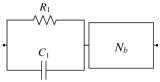
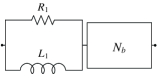
Consider a biquadratic impedance in the form of (IV.1) with , , , , , that cannot be realized as a series-parallel network containing fewer than seven elements. If is realizable as a three-reactive seven-element series-parallel network as shown in Fig. 2(a), where is a three-element series-parallel network and is a four-element series-parallel network, then is also realizable as shown in Fig. VI.1, where is a two-reactive five-element series-parallel network.
Proof:
By [15, Lemma 2], cannot be realized as the series connection of two networks, one of which only contains reactive elements. Therefore, must contain one or two reactive elements. If contains two reactive elements, then contains one reactive element. Therefore, the degree [2, Section 3.6] of cannot exceed one by [2, Theorem 4.4.3], where denotes the impedance of . By the discussion in [15], is realizable as a one-reactive three-element series-parallel network, which implies that is realizable with a series-parallel network containing fewer than seven elements. This contradicts the assumption. If contains one reactive element, then the degree [2, Section 3.6] of cannot exceed one by [2, Theorem 4.4.3], where denotes the impedance of . By the discussion in [15], is realizable as a one-reactive three-element series-parallel network, which is equivalent to one of configurations in Fig. VI.2. Regarding the series connection of and as , this lemma is proved. ∎
VII Complete Proof of Lemma 2
Assume that is realizable as in Fig. VI.1(a), where is a two-reactive five-element series-parallel network. Let , where is the impedance of the parallel connection of and and is the impedance of . It is clear that can be written in the form of
where . Since the condition of Theorem 1 does not hold, cannot be equivalent to a network containing fewer than five elements. Therefore, can be expressed in the form of
where , , , and the condition of Lemma V.3 holds. Since
it follows that . Therefore,
| (VII.1) |
Since , , it follows from (VII.1) that
| (VII.2) |
If satisfies Condition 1 of Lemma V.3, then and . Together with (VII.1), one obtains
| (VII.3) | ||||
| (VII.4) |
If , then it is obvious that the condition of Theorem 1 holds. If or , then it follows from (VII.4) that . Together with (VII.2), one obtains , which implies . Therefore, the condition of Theorem 1 holds.
If satisfies Condition 2 of Lemma V.3, then and . Together with (VII.1), one obtains (VII.3) and
| (VII.5) |
It follows from (VII.5) that . If , then it is obvious that the condition of Theorem 1 holds. If , then (VII.3) implies that
| (VII.6) |
From (VII.2) and (VII.6), it follows that , which implies . Therefore, the condition of Theorem 1 holds.
If satisfies Condition 3 of Lemma V.3, then and . Together with (VII.1), one obtains
| (VII.7) | ||||
| (VII.8) |
It follows from (VII.8) that . Therefore, the condition of Theorem 1 holds.
If satisfies Condition 4 of Lemma V.3, then and . Together with (VII.1), one obtains (VII.7) and
| (VII.9) |
It follows from (VII.9) that . Therefore, the condition of Theorem 1 holds.
This means that cannot be realized as in Fig. VI.1(a), where is a two-reactive five-element series-parallel network. It is clear that any network in Fig. VI.1(b) can be a frequency inverse network of another one in Fig. VI.1(a). Therefore, by the principle of frequency inverse (Section III), cannot be realized as in Fig. VI.1(b), where is a two-reactive five-element series-parallel network.
By Lemma V.3, cannot be realized as a three-reactive seven-element series-parallel network as shown in Fig. 2(a), where is a three-element series-parallel network and is a four-element series-parallel network. Since any network in Fig. 2(b), where is a three-element series-parallel network and is a four-element series-parallel network, can be a dual network of the case of Fig. 2(a), by the principle of duality (Section III), this lemma can be proved.
VIII Supplementary Lemmas of Four-Reactive Seven-Element Series-Parallel Realizations for the Proof of Lemma 3
Lemma VIII.1
Consider the four-reactive seven-element series-parallel network in Fig. 2, realizing a biquadratic impedance in the form of (IV.1) with , , , , , , where is a two-reactive three-element series-parallel network and is a two-reactive four-element series-parallel network. If cannot be realized as a series-parallel network containing fewer than seven elements, then must be one of the configurations in Fig. VIII.1.

Proof:
Let denote the cut-set [13, pg. 28] separating a one-terminal-pair labeled graph of a network into two connected subgraphs containing two terminal vertices and , respectively. By [15, Lemma 1], for any realization of there is no cut-set corresponding to only one kind of reactive elements, where and denote two terminals. Since contains three elements, all the possible network graphs [5] of are listed as in Fig. VIII.2. By the method of enumeration, this lemma can be proved. ∎
Lemma VIII.2
A biquadratic impedance cannot be realized as in Fig. 2(a), where is the configuration in Fig. VIII.1(a) and is a two-reactive four-element series-parallel network.
Proof:
By calculation, the impedance of the configuration in Fig. VIII.1(a) is obtained as
Since by assumption the condition of Theorem 1 does not hold, cannot be equivalent to a series-parallel network containing fewer than four elements. If is realizable as in Fig. 2(a), where is the configuration in Fig. VIII.1(a) and is a two-reactive four-element series-parallel network, then the impedance of is in the form of
where , and the impedance of is in the form of
| (VIII.1) |
where , , , and moreover the condition of Lemma V.2 holds. Since , it follows that
| (VIII.2) | ||||
| (VIII.3) |
Since , , satisfies neither Condition 1 nor Condition 2 of Lemma V.2.
If satisfies Condition 3 of Lemma V.2, then . Together with (VIII.3), it follows that , which contradicts the assumption.
If satisfies Condition 4 of Lemma V.2, then and either or holds. For the case of , together with (VIII.2) and (VIII.3), one obtains , , and , which implies by , , . Thus, the condition of Theorem 1 holds. For the case of , together with (VIII.2) and (VIII.3), one obtains
| (VIII.4) |
or
| (VIII.5) |
Because , , , it follows from (VIII.4) that , which satisfies the condition of Theorem 1. Substituting (VIII.5) into yields , which is impossible.
If satisfies Condition 5 of Lemma V.2, then and either or holds. For the case of , together with (VIII.2) and (VIII.3), one obtains , , and , which implies because , , . Thus, the condition of Theorem 1 holds. For the case of , together with (VIII.2) and (VIII.3), one obtains
| (VIII.6) |
or
| (VIII.7) |
It follows from (VIII.6) that by , , . Thus, the condition of Theorem 1 holds. Substituting (VIII.7) into yields , which is impossible.
If satisfies Condition 6 of Lemma V.2, then . Together with (VIII.2) and (VIII.3), one obtains , , and or , , and , which contradicts the assumption that , , .
As a conclusion, this lemma is proved. ∎
Lemma VIII.3
Proof:
First, the case where is a configuration in Fig. VIII.1(b) and is a two-reactive four-element series-parallel network will be discussed.
It is calculated that the impedance of the configuration in Fig. VIII.1(b) is in the form of
| (VIII.8) |
Since it is assumed that the condition of Theorem 1 does not hold, cannot be equivalent to a series-parallel network containing fewer than four elements. If is realizable as in Fig. 2(a), where is the configuration in Fig. VIII.1(b) and is a two-reactive four-element series-parallel network, then the impedance of is in the form of
where , and the impedance of is in the form of (VIII.1), where , , , and the condition of Lemma V.2 holds. Since , it follows that
| (VIII.9) | ||||
| (VIII.10) |
If satisfies Condition 1 of Lemma V.2, then , , , and . Together with (VIII.9) and (VIII.10), one obtains
| (VIII.11) |
which implies by , . Substituting (VIII.11) into yields . This implies , which satisfies the condition of Lemma 1.
If satisfies Condition 2 of Lemma V.2, then , , , and . Together with (VIII.9) and (VIII.10), one obtains
| (VIII.12) |
which implies by , . Substituting (VIII.12) into yields . This further implies . Therefore, the condition of Lemma 1 holds.
If satisfies Condition 3 of Lemma V.2, then , , and . Together with (VIII.9) and (VIII.10), one obtains , , and , which contradicts the assumption.
If satisfies Condition 4 of Lemma V.2, then , , , , and either or . For the case of , together with (VIII.9) and (VIII.10), one obtains
| (VIII.13) |
Substituting (VIII.13) into yields , which implies together with (VIII.13) by , , . Thus, the condition of Lemma 1 holds. For the case of , together with (VIII.9) and (VIII.10), one obtains
| (VIII.14) |
or
| (VIII.15) |
By , , , (VIII.14) is impossible. It is implied from (VIII.15) that , which satisfies the condition of Lemma 1.
If satisfies Condition 5 of Lemma V.2, then , , , , and either or . For the case of , together with (VIII.9) and (VIII.10), one obtains
| (VIII.16) |
Substituting (VIII.16) into yields , which implies together with (VIII.16) by , , . For the case of , together with (VIII.9) and (VIII.10), one obtains
| (VIII.17) |
or
| (VIII.18) |
It is obvious that (VIII.17) contradicts the assumption that , , . Moreover, it is implied from (VIII.18) that , which satisfies the condition of Theorem 1.
If satisfies Condition 6 of Lemma V.2, then , , and . Together with (VIII.9) and (VIII.10), one obtains
| (VIII.19) |
or
| (VIII.20) |
Consider the solutions in (VIII.19). Assume that . Then, since and . This contradicts the assumption. Assume that . Then, since and . This also contradicts the assumption. Consider the solutions in (VIII.20). Assume that . Then, because of . This contradicts the assumption. Assume that . Then, because of . This also contradicts the assumption.
Therefore, it can be proved that if a biquadratic impedance is realizable as in Fig. 2(a), where is one of the configurations in Fig. VIII.1(b) and is a two-reactive four-element series-parallel network, then the condition of Lemma 1 holds.
Then, it turns to the case where is a configurations in Figs. VIII.1(c) and is a two-reactive four-element series-parallel network.
It is calculated that the impedance of the configuration in Fig. VIII.1(c) is in the form of
| (VIII.21) |
Since it is assumed that the condition of Theorem 1 does not hold, cannot be equivalent to a series-parallel network containing fewer than four elements. If is realizable as in Fig. 2(a), where is the configuration in Fig. VIII.1(c) and is a two-reactive four-element series-parallel network, then the impedance of is in the form of
where , and the impedance of is in the form of (VIII.1), where , , , and the condition of Lemma V.2 holds. Since , it follows that
| (VIII.22) | ||||
| (VIII.23) |
If satisfies Condition 1 of Lemma V.2, then , , , and . Together with (VIII.22) and (VIII.23), one obtains
| (VIII.24) |
which implies by . Substituting (VIII.24) into yields , which further implies together with (VIII.24). Thus, the condition of Lemma 1 holds.
Since , cannot satisfy Condition 2 of Lemma V.2.
If satisfies Condition 3 of Lemma V.2, then , , and . Together with (VIII.22) and (VIII.23), one obtains
which implies by , , . Thus, the condition of Lemma 1 holds.
If satisfies Condition 4 of Lemma V.2, then , , , , and either or . For the case of , together with (VIII.22) and (VIII.23), one obtains
which implies or by , , . Thus, the condition of Lemma 1 holds. For the case of , together with (VIII.22) and (VIII.23), one obtains
| (VIII.25) |
or
| (VIII.26) |
where or must hold to guarantee the existence of the solutions. Consider the solutions in (VIII.25). Substituting (VIII.25) into yields
| (VIII.27) |
It is further implied from (VIII.27) that . Moreover, since , it is implied that , which satisfies the condition of Theorem 1. Consider the solutions in (VIII.26). The assumption that , implies or . Assume that . Then, since and . This contradicts the assumption.
If satisfies Condition 5 of Lemma V.2, then , , , , and either or . For the case of , together with (VIII.22) and (VIII.23), one obtains
| (VIII.28) |
or
| (VIII.29) |
where must hold to guarantee the existence of the solutions. Assume that . It is implied from (VIII.28) and (VIII.29) that , which contradicts the assumption. Assume that . For (VIII.28), it is derived that since . This contradicts the assumption. For (VIII.29), it is derived that , , since , , and . This also contradicts the assumption.
If satisfies Condition 6 of Lemma V.2, then , , and . Together with (VIII.22) and (VIII.23), one obtains
| (VIII.30) |
or
| (VIII.31) |
It is obvious that (VIII.30) is impossible. For (VIII.31), one implies by , , . Thus, the condition of Lemma 1 holds.
Therefore, it can be proved that if a biquadratic impedance is realizable as in Fig. 2(a), where is one of the configurations in Fig. VIII.1(c) and is a two-reactive four-element series-parallel network, then the condition of Lemma 1 holds.
It is clear that any network in Fig. 2(a), where is a configuration in Fig. VIII.1(d) and is a two-reactive four-element series-parallel network can be a frequency inverse network of the case where is a configuration in Fig. VIII.1(c). By the principle of frequency inverse, if a biquadratic impedance is realizable as in Fig. 2(a), where is one of the configurations in Fig. VIII.1(d) and is a two-reactive four-element series-parallel network, then the condition of Lemma 1 holds. ∎
Lemma VIII.4
Consider the four-reactive seven-element series-parallel network in Fig. 2(a), realizing a biquadratic impedance in the form of (IV.1) with , , , , , , where is a one-reactive three-element series-parallel network and is a three-reactive four-element series-parallel network. If cannot be realized as a series-parallel network containing fewer than seven elements, then will be equivalent to one of the configurations in Fig. VIII.3, and will be equivalent to one of the configurations in Fig. VIII.4.
Proof:
For any realization of , there is no cut-set corresponding to one kind of reactive elements, where and denote two terminal vertices, by [15, Lemma 1]. The possible network graphs for subnetworks and are listed as in Figs. VIII.2 and VIII.5, respectively. Based on the method of enumeration and the equivalence in [10, Lemma 11], can be equivalent to one of configurations in Fig. VIII.3, and can be equivalent to one of configurations in Fig. VIII.4. ∎
Lemma VIII.5
Proof:
By calculation, the impedance of the configuration in Fig. VIII.4(a) is obtained as
| (VIII.32) |
If is realizable as in Fig. 2(a), where is the configuration in Fig. VIII.3(a) and is the configuration in Fig. VIII.4(a), then the impedance of is in the form of
| (VIII.33) |
where , , and
| (VIII.34) |
holds, and moreover the impedance of is in the form of
| (VIII.35) |
where , . Then, it follows from (VIII.32) and (VIII.35) that
| (VIII.36) | ||||
| (VIII.37) | ||||
| (VIII.38) | ||||
| (VIII.39) | ||||
| (VIII.40) |
From (VIII.36), one obtains
| (VIII.41) |
It follows from (VIII.38) and (VIII.41) that
| (VIII.42) |
By (VIII.37), (VIII.39), and (VIII.41), one obtains
| (VIII.43) |
By (VIII.37), (VIII.41), and (VIII.43), one obtains
| (VIII.44) |
Substituting (VIII.41)–(VIII.44) into (VIII.40) gives
| (VIII.45) |
The assumption that and gives
| (VIII.46) |
Based on (VIII.33) and (VIII.35), calculation yields
| (VIII.47) |
Comparing (1) with (VIII.47), one obtains
| (VIII.48) | ||||
| (VIII.49) | ||||
| (VIII.50) | ||||
| (VIII.51) |
Then, (VIII.48) and (VIII.50) together yield
| (VIII.52) |
By (VIII.48), (VIII.49), and (VIII.52), one obtains
| (VIII.53) |
By (VIII.48) and (VIII.51), one obtains
| (VIII.54) |
Together with (VIII.48) and (VIII.52)–(VIII.54), condition (VIII.34) is equivalent to , and (VIII.45) and (VIII.46) are equivalent to
| (VIII.55) | ||||
| (VIII.56) |
respectively. Then, it follows from (VIII.55) and (VIII.56) that , which is impossible.
Therefore, cannot be realized as in Fig. 2(a), where is the configuration in Fig. VIII.3(a), and is the configurations in Fig. VIII.4(a).
It is calculated that the impedance of the configuration in Fig. VIII.4(c) is
| (VIII.57) |
If is realizable as in Fig. 2(a), where is the configuration in Fig. VIII.3(a) and is the configuration in Fig. VIII.4(c), then the impedance of is in the form of (VIII.33), where , , and (VIII.34) holds, and the impedance of is in the form of
| (VIII.58) |
where , . Then, it follows from (VIII.57) and (VIII.58) that
| (VIII.59) | ||||
| (VIII.60) | ||||
| (VIII.61) | ||||
| (VIII.62) | ||||
| (VIII.63) |
It follows from (VIII.59) that
| (VIII.64) |
By (VIII.62) and (VIII.64), one obtains
| (VIII.65) |
By (VIII.60), (VIII.61), and (VIII.64), one obtains
| (VIII.66) |
Then, (VIII.60), (VIII.64), and (VIII.66) yield
| (VIII.67) |
Then, it follows from (VIII.63)–(VIII.67) that
| (VIII.68) |
The assumption that and gives
| (VIII.69) |
By (VIII.33) and (VIII.58), is calculated as
| (VIII.70) |
Comparing (1) with (VIII.70), one obtains
| (VIII.71) | ||||
| (VIII.72) | ||||
| (VIII.73) | ||||
| (VIII.74) |
Then, (VIII.74) yields
| (VIII.75) |
By (VIII.71), (VIII.72), and (VIII.75), one obtains
| (VIII.76) |
It follows from (VIII.71), (VIII.73), and (VIII.75) that
| (VIII.77) |
Together with (VIII.71) and (VIII.75)–(VIII.77), condition (VIII.34) is equivalent to , and (VIII.68) and are equivalent to
| (VIII.78) |
and
| (VIII.79) |
respectively. Combining (VIII.78) and (VIII.79), one obtains , which is impossible.
Therefore, cannot be realized as in Fig. 2(a), where is the configuration in Fig. VIII.3(a), and is the configurations in Fig. VIII.4(c).
It is calculated that the impedance of the configuration in Fig. VIII.4(d) is
| (VIII.80) |
If is realizable as in Fig. 2(a), where is the configuration in Fig. VIII.3(a) and is the configuration in Fig. VIII.4(d), then the impedance of is in the form of (VIII.33), where , , and (VIII.34) holds, and the impedance of is in the form of (VIII.58) where , . Then, it follows from (VIII.58) and (VIII.80) that
| (VIII.81) | ||||
| (VIII.82) | ||||
| (VIII.83) | ||||
| (VIII.84) | ||||
| (VIII.85) |
It follows from (VIII.81) that
| (VIII.86) |
By (VIII.82), (VIII.83), and (VIII.86), one obtains
| (VIII.87) |
Then, (VIII.83), (VIII.85), and (VIII.86) yield
| (VIII.88) |
It follows from (VIII.84), (VIII.86), and (VIII.88) that
| (VIII.89) |
By (VIII.83) and (VIII.89), one obtains
| (VIII.90) |
By (VIII.33) and (VIII.58), is calculated as (VIII.70). Then, one obtains (VIII.71)–(VIII.77). Furthermore, it follows from conditions (VIII.34) and (VIII.87) that , which satisfies the condition of Theorem 1.
Therefore, cannot be realized as in Fig. 2(a), where is the configuration in Fig. VIII.3(a), and is the configurations in Fig. VIII.4(d).
It is calculated that the impedance of the configuration in Fig. VIII.4(e) is
| (VIII.91) |
If is realizable as in Fig. 2(a), where is the configuration in Fig. VIII.3(a) and is the configuration in Fig. VIII.4(e), then the impedance of is in the form of (VIII.33), where , , and (VIII.34) holds, and the impedance of is in the form of
| (VIII.92) |
where , , . Then, it follows from (VIII.91) and (VIII.92) that
| (VIII.93) | ||||
| (VIII.94) | ||||
| (VIII.95) | ||||
| (VIII.96) | ||||
| (VIII.97) | ||||
| (VIII.98) |
It follows from (VIII.93) that
| (VIII.99) |
By (VIII.94), (VIII.96), and (VIII.99), one obtains
| (VIII.100) |
By (VIII.94), (VIII.99), and (VIII.100), one obtains
| (VIII.101) |
Then, (VIII.95), (VIII.99), and (VIII.100) yield
| (VIII.102) |
It follows from (VIII.97), (VIII.100), and (VIII.102) that
| (VIII.103) |
Moreover, substituting (VIII.99)–(VIII.102) into (VIII.98) yields
| (VIII.104) |
The assumption that , , and gives
| (VIII.105) |
By (28) and (VIII.92), is calculated as
| (VIII.106) |
Comparing (1) with (VIII.106), one obtains
| (VIII.107) | ||||
| (VIII.108) | ||||
| (VIII.109) | ||||
| (VIII.110) |
Then, (VIII.107) and (VIII.108) yield
| (VIII.111) |
By (VIII.103) and (VIII.110), one obtains
| (VIII.112) |
By (VIII.111) and (VIII.112), one obtains
| (VIII.113) |
and
| (VIII.114) |
Then, (VIII.107), (VIII.109), and (VIII.114) yield
| (VIII.115) |
It follows from (VIII.110) and (VIII.114) that
| (VIII.116) |
Based on (VIII.107) and (VIII.114), one implies that (VIII.1) is equivalent to
| (VIII.117) |
which implies . Since the condition of Theorem 1 does not hold, one only needs to consider to the case of . Furthermore, (VIII.105) is equivalent to
| (VIII.118) |
by (VIII.113) and (VIII.115). Combining (VIII.117) and (VIII.118), one obtains
which implies . Therefore, the condition of Theorem 1 holds.
Lemma VIII.6
Proof:
It is calculated that the impedance of the configuration in Fig. VIII.4(b) is
| (VIII.119) |
If is realizable as in Fig. 2(a), where is the configuration in Fig. VIII.3(a) and is the configuration in Fig. VIII.4(b), then the impedance of is in the form of (VIII.33), where , , and (VIII.34) holds, and the impedance of is in the form of
| (VIII.120) |
where , . Then, it follows from (VIII.119) and (VIII.120) that
| (VIII.121) | ||||
| (VIII.122) | ||||
| (VIII.123) | ||||
| (VIII.124) | ||||
| (VIII.125) |
By (VIII.121), (VIII.124), and (VIII.125), one obtains
| (VIII.126) |
Then, (VIII.121), (VIII.123), and (VIII.126) yield
| (VIII.127) |
By (VIII.124) and (VIII.127), one obtains
| (VIII.128) |
Then, (VIII.121), (VIII.122), (VIII.127), and (VIII.128) yield
| (VIII.129) |
By (VIII.33) and (VIII.120), is calculated as
| (VIII.130) |
Comparing (1) with (VIII.130), one obtains
| (VIII.131) | ||||
| (VIII.132) | ||||
| (VIII.133) | ||||
| (VIII.134) |
By (VIII.134), one obtains
| (VIII.135) |
Then, (VIII.132) and (VIII.135) yield
| (VIII.136) |
By (VIII.131) and (VIII.136), one obtains
| (VIII.137) |
It follows from (VIII.133), (VIII.135), and (VIII.136) that
| (VIII.138) |
Together with (VIII.135)–(VIII.138), condition (VIII.34) is equivalent to , and (VIII.129) and are equivalent to
| (VIII.139) |
and
| (VIII.140) |
respectively. Combining (VIII.139) and (VIII.140), one obtains , which satisfies the condition of Lemma 1.
Therefore, if a biquadratic impedance is realizable as in Fig. 2(a), where is the configuration in Fig. VIII.3(a) and is one of the configurations in Figs. VIII.4(b), then the condition of Lemma 1 holds.
It is calculated that the impedance of the configuration in Fig. VIII.4(f) is
| (VIII.141) |
If is realizable as in Fig. 2(a), where is the configuration in Fig. VIII.3(a) and is the configuration in Fig. VIII.4(f), then the impedance of is in the form of (VIII.33), where , , and (VIII.34) holds, and the impedance of is in the form of (VIII.92), where , , . Then, it follows from (VIII.92) and (VIII.141) that
| (VIII.142) | ||||
| (VIII.143) | ||||
| (VIII.144) | ||||
| (VIII.145) | ||||
| (VIII.146) | ||||
| (VIII.147) |
It follows from (VIII.142) that
| (VIII.148) |
Then, (VIII.144), (VIII.146), and (VIII.148) yield
| (VIII.149) |
By (VIII.145) and (VIII.149), one obtains
| (VIII.150) |
Then, it follows from (VIII.144), (VIII.148), and (VIII.149) that
| (VIII.151) |
By (VIII.143) and (VIII.148)–(VIII.150), one obtains
| (VIII.152) |
The assumption that , , and gives
| (VIII.153) |
Then, (VIII.147)–(VIII.151) yield
| (VIII.154) |
By (28) and (VIII.92), is calculated as
| (VIII.155) |
Comparing (1) with (VIII.155), one obtains
| (VIII.156) | ||||
| (VIII.157) | ||||
| (VIII.158) | ||||
| (VIII.159) |
Then, it follows from (VIII.152) and (VIII.156)–(VIII.158) that
| (VIII.160) | ||||
| (VIII.161) |
By (VIII.159) and (VIII.161), one obtains
| (VIII.162) |
Then, (VIII.152) and (VIII.160) yield
| (VIII.163) |
Together with (VIII.156) and (VIII.161), condition (VIII.34) is equivalent to , which satisfies the condition of Lemma 1.
Lemma VIII.7
Proof:
The realizability condition of a general biquadratic impedance in the form of (IV.1) as a configuration that is equivalent to Fig. 3(a) is available in [11, Table I]. Letting , , , , , and for , the realizability condition for such a specific biquadratic impedance can be derived.
The element values can be derived as , , , , , , and , where , , , and is a positive root of . ∎
Lemma VIII.8
Proof:
By calculation, the impedance of the configuration in Fig. VIII.4(h) is obtained as
| (VIII.166) |
If is realizable as in Fig. 2(a), where is the configuration in Fig. VIII.3(a) and is the configuration in Fig. VIII.4(h), then the impedance of is in the form of (VIII.33), where , , and (VIII.34) holds, and moreover the impedance of is in the form of
| (VIII.167) |
where , , . Consequently, it follows from (VIII.166) and (VIII.167) that
| (VIII.168) | ||||
| (VIII.169) | ||||
| (VIII.170) | ||||
| (VIII.171) | ||||
| (VIII.172) | ||||
| (VIII.173) |
Thus, (VIII.169) yields
| (VIII.174) |
By (VIII.170) and (VIII.173), one obtains
| (VIII.175) |
It follows from (VIII.168), (VIII.170), and (VIII.174) that
| (VIII.176) |
By (VIII.168), (VIII.171), (VIII.175), and (VIII.176), one obtains
| (VIII.177) |
It follows from (VIII.172), (VIII.174), and (VIII.175) that
| (VIII.178) |
Based on (VIII.33) and (VIII.167), calculation yields
| (VIII.179) |
Comparing (1) with (VIII.179), one obtains
| (VIII.180) | ||||
| (VIII.181) | ||||
| (VIII.182) | ||||
| (VIII.183) |
It follows from (VIII.183) that
| (VIII.184) |
Thus, (VIII.178), (VIII.181), (VIII.182), and (VIII.184) together yield
| (VIII.185) |
and
| (VIII.186) |
By (VIII.180) and (VIII.186), one obtains
| (VIII.187) |
It follows from (VIII.178) and (VIII.185) that
| (VIII.188) |
Together with (VIII.184) and (VIII.186), condition (VIII.34) is equivalent to (VIII.164). Together with (VIII.185), (VIII.187), and (VIII.188), condition (VIII.177) is equivalent to
| (VIII.189) |
From (VIII.186), it follows that is equivalent to , which, in turn, is equivalent to , together with (VIII.164) and (VIII.189). Therefore, the condition of Lemma VIII.7 must hold. ∎
IX Supplementary Lemmas of Five-Reactive Seven-Element Series-Parallel Realizations for the Proof of Lemma 4
Lemma IX.1
Consider the five-reactive seven-element series-parallel network in Fig. 2(a), realizing a biquadratic impedance in the form of (IV.1) with , , , , , , where is a three-element series-parallel network and is a four-element series-parallel network. If cannot be realized as a series-parallel network containing fewer than seven elements, then is one of the configurations in Figs. VIII.1(b)–VIII.1(d) and will be equivalent to one of the configurations in Fig. VIII.4.
Proof:
By [15, Lemma 2], cannot be realized as the series connection of two networks, one of which contains only reactive elements. Therefore, can only contain two reactive elements. For any realization of , there is no cut-set corresponding to one kind of reactive elements, where and denote two terminals, by [15, Lemma 1]. The possible network graphs for subnetworks and are listed in Figs. VIII.2 and VIII.5, respectively. Based on the method of enumeration and the equivalence in [10, Lemma 11], is one of the configurations in Figs. VIII.1(b)–VIII.1(d) and can be equivalent to one of the configurations in Fig. VIII.4. ∎
Lemma IX.2
Proof:
It has been shown that the impedance of the configuration in Fig. VIII.1(b) is in the form of
| (IX.1) |
and the impedance of the configuration in Fig. VIII.4(a) is in the form of (VIII.32). Since it is assumed that the condition of Lemma 3 does not hold, cannot be realized with fewer than five reactive elements. If is realizable as in Fig. 2(a), where is the configuration in Fig. VIII.1(b) and is the configuration in Fig. VIII.4(a), then the impedance of is of degree two and is in the form of
| (IX.2) |
where , , , and the impedance of is of degree three and is in the form of (VIII.35), where , , and (VIII.45) and (VIII.46) hold. Furthermore,
| (IX.3) |
Comparing (1) with (IX.3), one obtains
| (IX.4) | ||||
| (IX.5) | ||||
| (IX.6) | ||||
| (IX.7) |
| (IX.8) |
By (IX.4), (IX.7), and (IX.8), one obtains
| (IX.9) |
It follows from (IX.8) and that , which further implies that by (IX.9). This is impossible.
Therefore, cannot be realized as in Fig. 2(a), where is the configuration in Fig. VIII.1(b) and is the configuration in Fig. VIII.4(a).
It is clear that any network in Fig. 2(a), where is the configuration in Fig. VIII.1(b) and is the configuration in Fig. VIII.4(b), can be a frequency inverse dual network of another one in Fig. 2(a), where is the configuration in Fig. VIII.1(b) and is the configuration in Fig. VIII.4(a). Based on the principle of frequency inverse, cannot be realized as such a network.
It has been shown that the impedance of the configuration in Fig. VIII.1(b) is in the form of (IX.1), and the impedance of the configuration in Fig. VIII.4(c) is in the form of . If is realizable as in Fig. 2(a), where is the configuration in Fig. VIII.1(b) and is the configuration in Fig. VIII.4(c), then the impedance of is of degree two and is in the form of (IX.2), where , , , and the impedance of is of degree three and is in the form of , where , . Furthermore,
| (IX.10) |
Comparing (1) with (IX.10), one obtains and , which further implies . This contradicts the assumption.
Therefore, cannot be realized as in Fig. 2(a), where is the configuration in Fig. VIII.1(b) and is the configuration in Fig. VIII.4(c).
It is clear that any network in Fig. 2(a), where is the configuration in Fig. VIII.1(b) and is the configuration in Fig. VIII.4(d), can be a frequency inverse dual network of another one in Fig. 2(a), where is the configuration in Fig. VIII.1(b) and is the configuration in Fig. VIII.4(c). Based on the principle of frequency inverse, cannot be realized as such a network.
It has been shown that the impedance of the configuration in Fig. VIII.1(b) is in the form of (IX.1), and the impedance of the configuration in Fig. 8(f) is in the form of (VIII.141). If is realizable as in Fig. 2(a), where is the configuration in Fig. VIII.1(b) and is the configuration in Fig. 8(f), then the impedance of is of degree two and is in the form of (IX.2), where , , and the impedance of is degree three and is in the form of (VIII.92), where , , and (VIII.152)–(VIII.154) hold. Furthermore, one obtains (IX.18)–(IX.25). Substituting (IX.19) and (IX.23)–(IX.25) into (VIII.152)–(VIII.154) yields
| (IX.11) | |||
| (IX.12) | |||
| (IX.13) |
respectively. By (IX.11), (IX.13) can be further equivalent to
| (IX.14) |
It is calculated that the resultant of (IX.11) and (IX.14) in is . Since the condition of Lemma 3 does not hold, there exists at least one common root between (IX.11) and (IX.14) in if and only if
| (IX.15) |
holds with , which implies that the condition of Lemma 3 holds. One further implies . By (IX.11), it is implied that (IX.12) is equivalent to
| (IX.16) |
By (IX.14), (IX.16) is further equivalent to , which is verified to be satisfied.
It is clear that any network in Fig. 2(a), where is the configuration in Fig. VIII.1(b) and is the configuration in Fig. VIII.4(h), can be a frequency inverse dual network of another one in Fig. 2(a), where is the configuration in Fig. VIII.1(b) and is the configuration in Fig. VIII.4(f). Based on the principle of frequency inverse, cannot be realized as such a network either. ∎
Lemma IX.3
A biquadratic impedance not satisfying the condition of Lemma 3 is realizable as in Fig. 2(a), where is the configuration in Fig. VIII.1(b) and is the configuration in Fig. VIII.4(e) (that is, the configuration in Fig. 4(a) whose one-terminal-pair labeled graph is ), if and only if
| (IX.17) |
and (it can be verified that there is only one distinct root of the equation for ).
Proof:
Necessity. It has been shown that the impedance of the configuration in Fig. VIII.1(b) is in the form of (IX.1), and the impedance of the configuration in Fig. VIII.4(e) is in the form of (VIII.91). Since it is assumed that the condition of Lemma 3 does not hold, cannot be realized with fewer than five reactive elements. If is realizable as in Fig. 2(a), where is the configuration in Fig. VIII.1(b) and is the configuration in Fig. VIII.4(e), then the impedance of is of degree two and is in the form of (IX.2), where , , , and the impedance of is of degree three and is in the form of (VIII.92), where , and (VIII.103)–(VIII.105) hold. Furthermore, one obtains
| (IX.18) |
Comparing (1) with (IX.18), one obtains
| (IX.19) | ||||
| (IX.20) | ||||
| (IX.21) | ||||
| (IX.22) |
Then, (IX.19) and (IX.20) yield
| (IX.23) |
By (IX.19) and (IX.21), one obtains
| (IX.24) |
It follows from (IX.19) and (IX.22) that
| (IX.25) |
Substituting (IX.19) and (IX.23)–(IX.25) into (VIII.103)–(VIII.105) yields
| (IX.26) |
| (IX.27) |
| (IX.28) |
respectively. It is calculated that the resultant of (IX.26) and (IX.27) in is . Since the condition of Lemma 3 does not hold, there exists at least one common root between (IX.26) and (IX.27) in if and only if (6) holds with . One implies . By (IX.26), it is implied that (IX.28) is equivalent to
| (IX.29) |
Based on (IX.27), one implies that (IX.29) is equivalent to , which can be verified to be satisfied.
Sufficiency. Based on the discussion in the necessity part, there exists such that (IX.26)–(IX.28) hold. Let , , , and satisfy (IX.19) and (IX.23)–(IX.25), which obviously implies that , , , . Therefore, (VIII.103)–(VIII.105) and (IX.20)–(IX.22) hold. Therefore, can be written in the form of (IX.18). Decompose as , where is in the form of (IX.2) where , , and is in the form of (VIII.92) where , . By letting , , and , is realizable as in Fig. VIII.1(b). Let , , , and satisfy (VIII.99)–(VIII.102). Since (VIII.105) holds, , , , . Based on the discussion in the proof of Lemma 11, it follows that (VIII.93)–(VIII.98) hold because (VIII.103) and (VIII.104) are satisfied. Therefore, can be realized as in Fig. VIII.4(e). The sufficiency part is proved. ∎
Lemma IX.4
Proof:
It has been shown that the impedance of the configuration in Fig. VIII.1(c) is in the form of , and the impedance of the configuration in Fig. VIII.4(a) is in the form of (VIII.32). Since it is assumed that the condition of Lemma 3 does not hold, cannot be realized with fewer than five reactive elements. If is realizable as in Fig. 2(a), where is the configuration in Fig. VIII.1(c) and is the configuration in Fig. VIII.4(a), then the impedance of is in the form of
| (IX.30) |
where , , and , and the impedance of is in the form of (VIII.35), where , , and moreover (VIII.45) and (VIII.46) hold. Furthermore,
| (IX.31) |
Comparing (1) with (IX.31), one obtains
| (IX.32) | ||||
| (IX.33) | ||||
| (IX.34) | ||||
| (IX.35) |
Then, it follows from (IX.32) and (IX.33) that
| (IX.36) |
Substituting (IX.32), (IX.35), and (IX.36) into (VIII.45), (VIII.46), and (IX.34) yields
| (IX.37) |
| (IX.38) |
| (IX.39) |
respectively. By (IX.36), the assumption of implies
| (IX.40) |
By calculation, the resultant of (IX.38) and (IX.39) in is . Since the condition of Lemma 3 does not hold, there exists at least one common root in between (IX.38) and (IX.39) if and only if
| (IX.41) |
holds with , which implies that the condition of Lemma 3 holds. This further implies that . From (IX.39), it follows that (IX.37) is equivalent to
| (IX.42) |
By (IX.38), one has that (IX.42) is further equivalent to , which can indeed be verified to be true.
It has been shown that the impedance of the configuration in Fig. VIII.1(c) is in the form of (VIII.21), and the impedance of the configuration in Fig. 8(f) is in the form of (VIII.141). If is realizable as in Fig. 2(a), where is the configuration in Fig. VIII.1(c) and is the configuration in Fig. VIII.4(f), then the impedance of is in the form of (IX.30), where , , and , and the impedance of is in the form of (VIII.92), where , , and (VIII.152)–(VIII.154) hold. Furthermore, one obtains (IX.50)–(IX.54). It follows from (VIII.154) and (IX.54) that
| (IX.43) |
Then, (VIII.152) and (IX.43) yield
| (IX.44) |
Substituting (IX.51), (IX.54), (IX.55), and (IX.44) into (VIII.153), (IX.52), and (IX.53) gives
| (IX.45) | ||||
| (IX.46) | ||||
| (IX.47) |
respectively. It is obvious that (IX.45) holds. It is calculated that the resultant of (IX.46) and (IX.47) in is . Since the condition of Lemma 3 does not hold, it is implied that there exists at least one common root between (IX.46) and (IX.47) if and only if
| (IX.48) |
holds with , which implies that the condition of Lemma 3 holds. This further implies that . ∎
Lemma IX.5
A biquadratic impedance not satisfying the condition of Lemma 3 is realizable as in Fig. 2(a), where is the configuration in Fig. VIII.1(c) and is the configuration in Fig. VIII.4(e) (that is, the configuration in Fig. 5(a) whose one-terminal-pair labeled graph is ), if and only if
| (IX.49) |
and (it can be verified that the equation has only one distinct root for ).
Proof:
Necessity. It has been shown that the impedance of the configuration in Fig. VIII.1(c) is in the form of (VIII.21), and the impedance of the configuration in Fig. VIII.4(e) is in the form of (VIII.91). Since it is assumed that the condition of Lemma 3 does not hold, cannot be realized with fewer than five reactive elements. If is realizable as in Fig. 2(a), where is the configuration in Fig. VIII.1(c) and is the configuration in Fig. VIII.4(e), then the impedance of is in the form of (IX.30), where , , and , and the impedance of is in the form of (VIII.92), where , , and (VIII.103)–(VIII.105) hold. Furthermore, one obtains
| (IX.50) |
Combining (1) with (IX.50), one obtains
| (IX.51) | ||||
| (IX.52) | ||||
| (IX.53) | ||||
| (IX.54) |
It follows from (VIII.103) and (IX.54) that
| (IX.55) |
By (VIII.104), (IX.54), and (IX.55), one obtains
| (IX.56) |
Substituting (IX.51) and (IX.54)–(IX.56) into (VIII.105), (IX.52), and (IX.53) gives
| (IX.57) | ||||
| (IX.58) |
and
| (IX.59) |
respectively. It is obvious that (IX.57) holds. It is calculated that the resultant of (IX.58) and (IX.59) in is . Since the condition of Lemma 3 does not hold, it is implied that there exists at least one common root between (IX.58) and (IX.59) if and only if (IX.49) holds with . This further implies that .
Sufficiency. Based on the discussion in the necessity part, there exists such that (IX.57)–(IX.59) hold. Let , , , and satisfy (IX.51) and (IX.54)–(IX.56), which implies , , , . Therefore, (VIII.103)–(VIII.105), (IX.52), and (IX.53) hold. Therefore, can be written in the form of (IX.50). Decompose as , where is in the form of (IX.30) with , , and , and is in the form of (VIII.92) with , , . By letting , , and , is realizable as in Fig. VIII.1(c). Let , , , and satisfy (VIII.99)–(VIII.102). Since (VIII.105) hold, , , , . Based on the discussion in the proof of Lemma 11, (VIII.93)–(VIII.98) hold. Therefore, can be realized as the configuration in Fig. VIII.4(e). The sufficiency part is proved. ∎
References
- [1] K. Wang, M. Z. Q. Chen, C. Li, and G. Chen, “Passive controller realization of a biquadratic impedance with double poles and zeros as a seven-element series-parallel network for effective mechanical control,” IEEE Trans. Automatic Control, vol. 63, no. 9, pp. 3010–3015, 2018.
- [2] B. D. O. Anderson and S. Vongpanitlerd, Network Analysis and Synthesis: A Modern Systems Theory Approach. NJ: Prentice Hall, 1973.
- [3] H. Baher, Synthesis of Electrical Networks. New York: Wiley, 1984.
- [4] M. Z. Q. Chen and M. C. Smith, “A note on tests for positive-real functions,” IEEE Trans. Automatic Control, vol. 54, no. 2, pp. 390–393, 2009.
- [5] M. Z. Q. Chen, K. Wang, Z. Shu, and C. Li, “Realizations of a special class of admittances with strictly lower complexity than canonical forms,” IEEE Trans. Circuits and Systems-I: Regular Papers, vol. 60, no. 9, pp. 2465–2473, 2013.
- [6] M. Z. Q. Chen, Y. Hu, C. Li, and G. Chen, “Performance benefits of using inerter in semiactive suspensions,” IEEE Trans. Control Systems Technology, vol. 23, no. 4, pp. 1571–1577, 2015.
- [7] R. M. Foster, “Academic and theoretical aspects of circuit theory,” Proceedings of the IRE, vol. 50, no. 5, pp. 866–871, 1962.
- [8] F. R. Gantmacher, The Theory of Matrices. New York: Chelsea, 1980, vol. II.
- [9] E. A. Guillemin, Synthesis of Passive Networks. New York: Wiley, 1957.
- [10] J. Z. Jiang and M. C. Smith, “Regular positive-real functions and five-element network synthesis for electrical and mechanical networks,” IEEE Trans. Automatic Control, vol. 56, no. 6, pp. 1275–1290, 2011.
- [11] J. Z. Jiang and S. Y. Zhang, “Synthesis of biquadratic impedances with a specific seven-element network,” in Proceedings of 2014 UKACC International Conference on Control, Loughborough, U.K., 2014, pp. 139–144.
- [12] C. Papageorgiou and M. C. Smith, “Positive real synthesis using matrix inequalities for mechanical networks: Application to vehicle suspension,” IEEE Trans. Control Systems Technology, vol. 14, no. 3, pp. 423–435, 2006.
- [13] S. Seshu and M. B. Reed, Linear Graphs and Electrical Networks. Boston: Addison-Wesley, 1961.
- [14] M. C. Smith and F.-C. Wang, “Performance benefits in passive vehicle suspensions employing inerters,” Vehicle System Dynamics, vol. 42, no. 4, pp. 235–257, 2004.
- [15] K. Wang, M. Z. Q. Chen, and Y. Hu, “Synthesis of biquadratic impedances with at most four passive elements,” Journal of the Franklin Institute, vol. 351, no. 3, pp. 1251–1267, 2014.