captionUnsupported document class (or package) detected
Bipedal Walking with Corrective Actions in the Tilt Phase Space
Abstract
Many methods exist for a bipedal robot to keep its balance while walking. In addition to step size and timing, other strategies are possible that influence the stability of the robot without interfering with the target direction and speed of locomotion. This paper introduces a multifaceted feedback controller that uses numerous different feedback mechanisms, collectively termed corrective actions, to stabilise a core keypoint-based gait. The feedback controller is experimentally effective, yet free of any physical model of the robot, very computationally inexpensive, and requires only a single 6-axis IMU sensor. Due to these low requirements, the approach is deemed to be highly portable between robots, and was specifically also designed to target lower cost robots that have suboptimal sensing, actuation and computational resources. The IMU data is used to estimate the yaw-independent tilt orientation of the robot, expressed in the so-called tilt phase space, and is the source of all feedback provided by the controller. Experimental validation is performed in simulation as well as on real robot hardware.
I Introduction
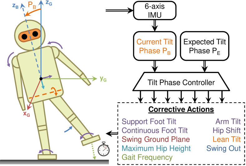
Many feedback strategies exist by which a robot can seek to maintain its balance while walking bipedally. Often considered is the online adjustment of step size and timing, e.g. [1]. While these are quite effective strategies if done right, numerous other forms of feedback beyond just ankle torque, such as for example arm motions and swing leg trajectory adjustments, can also be employed to significantly increase the stability of the robot, especially in a broader spectrum of walking situations. For instance, step size feedback cannot help when a robot is about to tip over the outside of one of its feet, or effectively correct for systematic biases in the robot. It also has little effect until the next step is actually taken, meaning that there is an inherent dead time until disturbances can be counteracted. Furthermore, changing the target step size modifies the footholds, and thus directly leads to the non-realisation of footstep plans. As such, step size feedback is envisioned as a valuable tool for gait stabilisation, but one that ideally only activates for large disturbances, when there really is no other option. The corrective actions presented in this paper (see Fig. 1) aim to address all of these issues, in addition to solving the more general problem of how to achieve balanced push-resistant walking, with minimal changes to the walking intent of the robot.
In the interest of reducing the required tuning effort and making the gait applicable to low-cost robots with cheap sensors and actuators, the use of physical models in the feedback path is avoided. Physical models usually require extensive model identification and tuning to sufficiently resemble the behaviour of a robot, and even then, cheap actuators lead to significant nonlinearities that can often cause such models to have poor results or fail. Physical models are also frequently quite sensitive to small changes in the robot, leading to frequent retuning being necessary. The implementation difficulty and cost of good sensors also limits the type and accuracy of sensors that can be incorporated into a humanoid robot. So to facilitate the greatest possible portability of the developed gait between robots of different builds and proportions—a design decision that is supported by the chosen model-free nature of the gait—only the presence of a 6-axis IMU sensor is assumed. Apart from that, no additional sensors, joint positions, robot masses or inertias are assumed at all for the feedback controller. The only further ‘assumptions’ that are made are trivial notions, such as for example that tilting the foot in one direction makes the robot tend to tilt in the other.
The main contributions of this paper lie in the methods of calculation of the various feedback components, which are extensions of previous work [2] only for the PD, leaning and timing components, and otherwise novel. Several corrective actions are also completely new, with the remaining ones being extended to a full 3D treatment, so as in particular not to treat the sagittal and lateral directions independently. This is aided by the novel use of the tilt phase space for truly axisymmetric orientation feedback. While the controller for the individual corrective actions is discussed in detail, how these actions are combined to form a single resulting joint trajectory is beyond the scope of this paper. The presented feedback controller has been released open source in C++ [3]. Ultimately, this paper seeks to demonstrate that not overly complex feedback mechanisms with very limited information of the robot suffice to produce a very stable gait, capable of rejecting significant disturbances.
II Related Work
Many different approaches to the stabilisation of bipedal walking can be found in literature. Methods that are effective in actively rejecting large disturbances, yet do not use a physical model and only use a single inertial measurement unit (IMU) for feedback, are however infrequently encountered. A large proportion of walking methods, especially those for stiffer and higher quality robots, depend on zero-moment point (ZMP) based gait generation and/or feedback. Usually this involves optimising for a future centre of mass (CoM) trajectory based on certain targets and constraints, and then trying to execute this as closely as possible with a lower level controller. Examples of this include in the settings of model predictive control [4], preview control [5] [6], and an indirect generalisation in the form of differential dynamic programming (DDP) [7]. Tedrake et al. [8] also proposed a closed-form solution to the full continuous-time ZMP LQR problem over large horizons, while Kajita et al. [9] use spatially quantised dynamics (SQD), as opposed to temporal quantisation, with a mix of reference ZMP trajectory generation and divergent component of motion (DCM) dynamics to generate a gait that was able to utilise fully stretched knees.
The main problem with implementing ZMP-based methods on low-cost robots is that such methods generally assume that actuator tracking is quite good, and that if theoretically stable motions are planned, then executing them will be essentially stable. ZMP reference tracking controllers aim to increase the margin of convergence and stability, but ZMP approaches frequently are just not designed to operate to the limits of stability, where for example a robot is completely tilted about one of the edges or even vertices of its feet, with significant energy and deviation from upright. ZMP tracking controllers also usually require direct sensing of the centre of pressure, which is usually not robustly available for limited sensing robots. The reliance on complex optimisation-based methods also means that computational requirements are high, as compared to the alternative of analytic computation.
The most closely related work to this paper is the work of the authors on direct fused angle feedback mechanisms [2]. The main differences and improvements of this paper are explicitly outlined in the aforementioned list of contributions.
III The Tilt Phase Space
One significant difference between [2] and this paper is the full 3D treatment given to the corrective actions, made possible in part by the use of the tilt phase space [10] instead of fused angles [11]. While fused angles work very well for separate treatments of the sagittal and lateral planes, the tilt phase space has advantages for concurrent treatments, in particular in relation to magnitude axisymmetry [10]. This is important to ensure that feedback magnitudes are the same scale no matter what continuous direction the robot is tilted in. Furthermore, the tilt phase parameters share all of the critical advantages [12] that fused angles have over lesser options, such as for example Euler angles, mainly due to the tight relationship between the two representations. Further advantages of the tilt phase space include that it can naturally represent and deal with tilt rotations of more than 180∘, and that using it, tilt rotations can be unambiguously commutatively added. Both of these are useful features in feedback scenarios where rotation deviation feedback components are scaled by gains and need to be combined.
If are the tilt angles parameters of a rotation, where is the fused yaw, is the tilt axis angle and is the tilt angle [11], the corresponding 3D tilt phase is
| (1) |
Omitting the yaw component, the 2D tilt phase representation of the resulting tilt rotation component is given by
| (2) |
Compare this to the following expressions for fused angles,
| (3) |
More details on all of the used rotation representations can be found in the
respective papers [10] [11] and code
releases.111 C++ Matlab:
https://github.com/AIS-Bonn/rot_conv_lib
https://github.com/AIS-Bonn/matlab_octave_rotations_lib
IV Gait Architecture
IV-A Overview
The gait architecture consists of three layers, evaluated at , spanning from the generation of low level servo commands in the bottom layer, through to the generation of the required joint trajectories in the middle layer, and the calculation of feedback corrective action activation values in the top layer. The individual layers are discussed as follows.
IV-A1 Actuator control scheme
In the lowest layer, the joint targets, joint efforts and support coefficients commanded by the middle layer are converted into raw actuator commands and stiffnesses that are communicated to the actuator hardware. This incorporates an optional feedforward torque component for improved tracking of the required trajectories. The actuator control scheme in use is thoroughly discussed in [2], and is useful to compensate for factors such as joint friction, battery voltage and the expected relative loadings of the legs—all nominally in a position-controlled setting.
IV-A2 Keypoint gait generator
The middle layer of the gait, referred to as the keypoint gait generator, is responsible for generating the required joint trajectories based on activation commands from the top layer. The implementation is something akin to an open-loop gait, albeit with the ability to activate a myriad of corrective actions, such as for example foot motions and hip shifts, which are ingrained into the construction of the gait. A full list is given in Section IV-B. Note that the keypoint gait generator is totally different to the central pattern generated gaits used in previous publications. Also, the implementations of the corrective actions, unlike for example in [2], are given a full explicit 3D treatment, and are handled as proper rotations and transformations in 3D space, as opposed to independent contributions to joint angles based on separate lateral and sagittal contributions. Nevertheless, even with no activations from the top layer, a partially passively stable omnidirectional gait can be achieved.
The keypoint gait generator is analytically computed as a function of the so-called gait phase , which is cyclically incremented over time based on the desired gait frequency. Every gait phase value uniquely corresponds to a particular instant of the stepping gait trajectory, where for example corresponds to the begin of the double support phase transitioning from left support to right support, and corresponds to the nominal moment of foot strike of the left foot. The keypoint gait generator is computed in a target- and constraint-based manner, as opposed to being manually constructed, and explicitly considers that the robot may nominally walk at some pitch angle relative to upright. This pitch angle defines a constant frame {N} and corresponding plane N relative to the body frame {B} of the robot, referred to as the nominal ground plane, that during ideal nominal walking would indicate the planar level of the ground. Although entirely novel, the inner workings of the keypoint gait generator are beyond the scope of this paper.
IV-A3 Higher level controller
The top layer of the presented gait architecture is generically referred to as the higher level controller, but more specifically in this case as the tilt phase controller. Its task is to compute, based on sensory feedback, activations of the corrective actions that robustly stabilise the gait and ensure the robot remains balanced. The sources of sensory feedback can hypothetically include anything, but in this paper are strictly limited to a single 6-axis IMU.
IV-B Corrective Actions
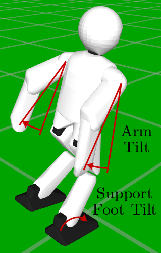
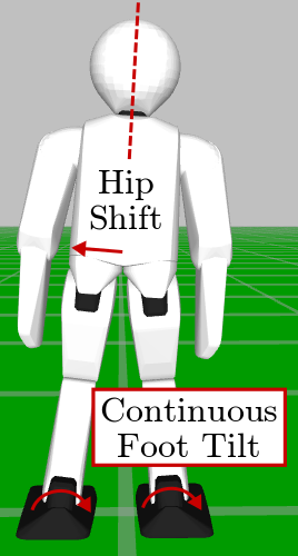
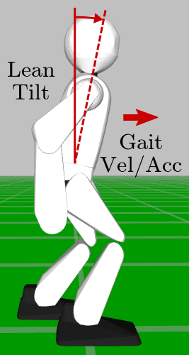
Numerous corrective actions have been implemented in the gait, as shown in Fig. 2. All cartesian actions are expressed in dimensionless form relative to the nominal ground plane N, in units of either the inverse leg scale or tip leg scale of the robot. These are respectively the vertical distances in the zero pose between the hip point and ankle point, and between the hip point and foot geometric centre. All rotation-based actions are expressed in the 2D tilt phase space, as pure tilt rotations relative to N. Pure tilt rotations are rotations with a zero fused yaw component, i.e. pure rotations about an axis in the horizontal xy-plane. The implemented corrective action activations are as follows:
-
•
The arm tilt to apply to the arms, to shift their CoMs and cause corresponding reaction moments.
-
•
The support foot tilt to apply to the feet during their respective support phases, with smooth transitions in the adjoining double support phases.
-
•
The continuous foot tilt to apply to the feet as constant offsets throughout the entire trajectory.
-
•
The dimensionless hip shift to apply to the robot in units of inverse leg scale.
-
•
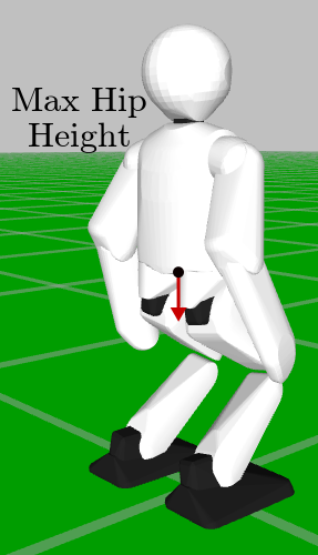
The maximum hip height to allow relative to the feet for the generated gait, in units of leg tip scale.
-
•
The lean tilt to apply to the robot torso, causing the robot to lean primarily via its hip joints.
-
•
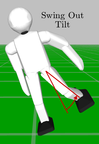
The swing out tilt to smoothly apply to the midpoint of the swing trajectory, to adjust the path taken by the swing leg to its foot strike location.
-
•
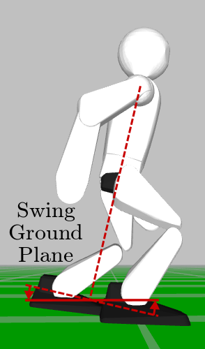
The tilt defining the swing ground plane S relative to the N plane. This is the plane that is used to adjust the relative foot heights and tilts generated by the gait for orientation deviations in the trunk.
-
•
The gait frequency to use, in , as the required instantaneous rate of change for updating the gait phase.
Note that all activations are expressed in a dimensionless manner so that almost exactly the same values can be used for robots of different scales. The configurable constants that are used throughout this gait also follow the same approach.
The corrective actions were not arbitrarily chosen, but were the result of an analysis of the conceivable strategies for balanced bipedal walking. A commanded gait velocity could easily be added to the list of corrective actions if an additional step size adjustment scheme is wished in parallel.
V Tilt Phase Controller
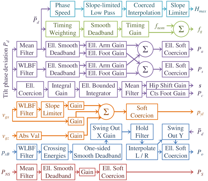
An overview of the feedback pipeline is shown in Fig. 3. The individual actions are presented in detail in this section.
V-A Preliminaries
The tilt phase controller utilises a number of recurring filters and mathematical constructs, discussed as follows.
V-A1 Filters
The mean and weighted line of best fit (WLBF) filters from [2] have been taken and generalised to dimensions. The former computes the moving average of an -dim vector, while the latter performs weighted time-based linear least squares regression to smooth and estimate the derivative of -dim data. The advantages of WLBF filters over alternatives for the numerical computation of derivatives are discussed in depth in [2].
V-A2 Coerced interpolation
Standard linear interpolation can lead to extrapolation outside of the interval domain. Coerced interpolation limits the input variable to ensure that the output cannot be outside the range of the two data points.
V-A3 Soft Coercion
The soft coercion from [2] has been used and extended ellipsoidally to dimensions. Given an input vector , the principal semi-axis lengths of the limiting ellipsoid , and a soft coercion buffer , symmetric soft coercion of buffer is applied radially along to the radius of . This is significantly better than applying soft limits along each axis independently, as the latter would result in unexpectedly large radial limits inbetween the principal axes.
V-A4 Smooth Deadband
The smooth deadband from [2] has been used and extended ellipsoidally to dimensions. Given an input vector and the principal semi-axis lengths of the deadband ellipsoid , scalar smooth deadband is applied radially along with a deadband radius of the radius of .
V-B Deviation Tilt
In the tilt phase controller, most of the activations of the corrective actions depend directly on how the robot is currently tilted relative to what is expected for the current gait phase. Based on the 3-axis accelerometer and gyroscope measurements from the IMU in the trunk of the robot, the tilt phase orientation of the robot is estimated using a 3D nonlinear passive complementary filter [13]. Note that the yaw component is not included here as it does not directly contribute to the local balance state of the robot, and cannot be estimated drift-free based only on the IMU.
The two estimated tilt phase parameters follow an expected periodic pattern during ideal undisturbed walking of the robot, modelled as a map from to . Thus, by evaluation of this map, the expected tilt phase parameters for the body of the robot can be calculated in every cycle. In this work, a sinusoidal map with an offset is used in both dimensions, as it sufficiently describes and generalises the observed data from the tested robots.
The corrective actions in the keypoint gait generator are defined so that they physically act to cause tilts relative to the N plane, just like the definitions of their respective activations (see Section IV-B). Thus, an error term is constructed as a basis for feedback that quantifies the inverse of the unique tilt rotation relative to N that rotates the body frame {B} to have the expected tilt phase parameters . The so-called deviation tilt is calculated using
| (4) |
where is the solution to , and is the fused yaw of , and are the quaternions corresponding to pure y- and z-rotations by , is the nominal ground plane pitch, is the quaternion corresponding to the tilt phase , is the quaternion conjugation operator, and is the 2D tilt phase corresponding to the quaternion .
As an illustratory guide, at this point if the negative of the calculated deviation tilt were for example to be applied as an activation to any of the rotation-based corrective actions, the effect would be to induce a tilt of the robot torso in some way towards its expected tilt phase parameters . Thus, the feedback would act to return the robot towards nominal walking. Note however, that due to sensor noise and scaling issues, such direct feedback would not yet be effective.
V-C PD Feedback: Arm and Support Foot Tilt
The most important thing for the stability of the robot on the short-term is to ensure that transient disturbances, such as for example pushes or steps on larger irregularities in the ground, are swiftly counteracted, and with little delay. 3D rotational proportional (P) and derivative (D) feedback components, activating the arm tilt and support foot tilt corrective actions, are used for this purpose. The arm tilt rotates the CoM of the arms out in the required direction relative to the N plane, so as to bias the CoM of the entire robot, and also to apply a reactive moment on the torso of the robot that helps mitigate the disturbance. At the same time, the support foot tilt applies smooth temporary corrections to the tilt of each foot during its respective single support phase, to push the robot back towards its expected orientation.
In order to reduce signal noise, the P feedback component first mean filters the deviation tilt using a small filter order to give . This tilt phase is then elliptically smooth deadbanded to ensure that P feedback only takes effect when the robot is non-negligibly away from its expected orientation. An elliptically directionally dependent gain is then applied to the resulting tilt phase, once independently for each the arm tilt and the support foot tilt, to get the corresponding P feedback components. The gain in each case is calculated from specifications of the required gains in the sagittal and lateral directions. Importantly, the directions of the final feedback components are both unchanged from —all changes are purely radial.
For the D feedback, a smoothed derivative of is first computed using a 2D WLBF filter. A WLBF filter was chosen for its many advantages, including amongst other things for its favourable balance between robustness to high frequency noise and responsiveness to input transients [2]. The computed derivative is elliptically smooth deadbanded to ensure that D feedback only takes effect if the robot torso has a non-negligible angular velocity relative to its expected orientation. Then, as for the P feedback, independent elliptically directionally dependent gains are applied to get the D feedback components for the two PD corrective actions.
Once the separate P and D components have been calculated, they are combined using tilt vector addition [10] and elliptically soft-coerced to obtain the final activations and (see Section IV-B). Note that although it is not generally acceptable to just add 3D rotations, the special properties of the tilt phase space allow us to do just that in a meaningful, unambiguous, self-consistent and mathematically supported way. In fact, the tilt phase space turns tilt rotations into a well-defined vector space over , explaining why the scaling and addition of tilt phases that is used in this paper is actually mathematically valid and geometrically meaningful [10].
Tuning of the PD feedback is relatively straightforward, as there are only a few gains, and each gain has a clearly visible effect on the robot. The P feedback is tuned first, and then appropriated with D feedback to add damping to the system and limit oscillatory behaviour.
V-D I Feedback: Hip Shift and Continuous Foot Tilt
The implemented PD feedback works well for rejecting the majority of short-term transient disturbances, but if there are continued regular disturbances, or a systematic imbalance in the robot, the PD feedback in combination with other corrective actions will constantly need to act to oppose them. PD feedback can only act however, if there is a non-zero error present. Thus, without integral feedback on the hip shift and continuous foot tilt corrective actions, the system in such a case would at best settle with a steady state deviation to normal walking. The continuous foot tilt applies continuous tilt corrections to the generated orientations of the feet, while the hip shift applies an offset to the generated hip position relative to the feet. Both are applied relative to the N plane, and bias the balance of the robot in the desired direction to overcome systematic errors in the walking of the robot. The implemented I feedback can effectively reduce the need for fine tuning of the robot, and make the gait insensitive to small changes in the hardware or walking surface that would otherwise have been noticeable in the walking quality.
Starting with the deviation tilt , standard elliptical coercion is first applied, the output of which is scaled by a scalar integral gain. A scalar gain is used instead of a directionally dependent one, so as not to distort the ‘aggregated’ direction of instability once integration is applied. The initial coercion is useful to ensure that the integrated value is determined predominantly by small and consistent deviation tilts, rather than large and brief transients, which have little correlation to the finer balance of the robot. The coerced and scaled deviation tilt is passed to an elliptically bounded integrator. This kind of integrator performs updates of 2D trapezoidal integration and elliptical soft coercion in each step. Note that the two steps are interlinked, as the output of the coercion is used as the starting point for the next integral update. Apart from providing the required integral behaviour to eliminate steady state errors and ensuring that the integral remains conveniently bounded, this special kind of integrator also inherently combats integral windup. The initial coercion of reduces the extent to which integrator windup is possible, but the elliptically bounded integrator ensures that the integral can move away from the elliptical boundary as quickly as it can get there, and cannot get stuck there due to over-integration. The dynamic response of the corrective actions is on a much quicker time scale than the integration, so this is the main type of windup concern.
The integrated tilt phase value is passed through a final mean filter to combat ripple, before being separately scaled to get the final corrective action activations and . The order of the mean filter is chosen to correspond exactly to the duration of an even number of steps at the nominal gait frequency. Due to the periodicity and general regularity of the gait, this leads to almost perfect cancellation of ripple. This would not be achievable with an IIR filter, which would also have the downside of not as efficiently forgetting old data.
During tuning, it is attempted to keep at least one of the elliptical integral bounds at 1. This form of normalisation makes the tuning of the integral and corrective action gains relatively simple and intuitive, as the former then inversely relates to the parameters of the initial elliptical coercion, and the latter then corresponds to the desired maximum magnitude of each respective corrective action.
V-E Leaning
Leaning at the hips could be activated based on I feedback, but this would promote suboptimal walking postures of the robot, in part because it directly changes the measured orientation of the trunk without this necessarily ameliorating the overall balance of the robot. Leaning by PD feedback would also be possible, but although maybe not immediately intuitively obvious, neither attempting to lean forwards nor backwards is particularly useful for dissipating energy when for example falling forwards. Pure hip rotations are only useful if they are performed quite significantly, early enough before tipping, and in specific controlled scenarios, e.g. clean push disturbances, purely sagittal direction, not walking or immediately stop after disturbance, and so on. In most other situations, reactive leaning has a negative impact on walking robustness. As such, only feedforward leaning components based on the gait command velocity are implemented. These seek to avoid disturbances due to changes in walking velocity before they even occur. The gait acceleration is first estimated using a WLBF filter followed by a slope limiter. A linear combination of the sagittal velocity , absolute turning velocity and sagittal gait acceleration is then taken and soft-coerced to give (see Section IV-B). This feedforward of sagittal leaning helps in particular during strong turns, and when starting and stopping forwards walking.
V-F Swing Out
The robot is said to be on a lateral crossing trajectory if it has enough lateral momentum that it will tip over the outside of its support foot. This is a difficult situation, as no simple reactive stepping or waiting strategy can prevent the fall. Acting alongside the arm tilt and support foot tilt actions, the swing out tilt was specifically designed to allow recovery from crossing trajectories. When significant lateral energy is detected, the current swing leg is rotated outwards to bias the balance of the robot, and apply a reactive moment that dissipates crossing energy. The lateral tilt phase is first smoothed and differentiated using a WLBF filter. The line of best fit is evaluated at the mean of the recorded data points so that the estimated phase and phase velocity are synchronised in time. Modelling the behaviour of the lateral tilt phase as similar to a nonlinear pendulum gives that
| (5) |
is constant over an undisturbed trajectory, where is or depending on the support foot, is a constant, and
| (6) |
where is the phase at the point of crossing over foot . Adjusting the signs of the kinetic and potential energy components based on whether they are contributing to or hindering crossing, leads to the definition of crossing energy,
| (7) |
is a function of , is zero for lateral tilt phase trajectories that come to rest exactly on the verge of crossing, and is more positive the greater the severity of crossing. One-sided smooth deadband centred at some is then applied to the calculated , i.e. , values. The result is scaled to give an initial measure of how much swing out is required for each direction. The one-sided deadband ensures that the swing out is zero below an energy of , and smoothly transitions to a linear relationship beyond that. A pair of hold filters is applied to ensure that the greatest activation over the most recent time is kept and used for each side. The filtered lateral swing out values are interpolated linearly based on the expected support conditions, via the gait phase. At this point, a sagittal swing out component is added that ensures that the resultant swing out is, within limits, in the direction of . The final resulting swing out tilt is then elliptically soft-coerced to ensure that the swing out stays within reasonable limits. The tuning of swing out is done by examining crossing trajectories of the robot. The values are read from the points of inflection, and is chosen to give the most constant profiles possible of . A suitable value for can then be guessed and trimmed by calculating what stationary value of it should correspond to.
V-G Swing Ground Plane
While nominally the ground coincides with the N plane during walking, with disturbances this is no longer the case. This can cause premature foot strike, which is both destabilising and prevents the robot from taking the step size it should. The swing ground plane S defines the plane that is used to adjust the stepping trajectories to avoid such issues. This is different to most implementations of ‘virtual slope’ [2] [14] in that it does not just linearly slant the foot motion profile—it analytically computes a smooth trajectory that respects the S plane at foot strike, yet intentionally presses into or eases off the ground immediately after, so as to actually apply a restoring moment to the robot. Standard virtual slope implementations can in fact decrease walking robustness, as the more the robot leans forwards for instance, the higher the feet are lifted at the front, and thus the less resistance there actually is to falling forwards.
The S plane is first computed by finding a pure tilt rotation relative to N that makes the N plane coincident with where the N plane would be if the robot had its expected orientation . This pure tilt rotation is calculated using
| (8) |
where the same notation as in (4) is used. Note that when the robot has its expected orientation, i.e. . To reduce noise and prevent S plane adjustments from being made when walking is near nominal, a mean filter followed by elliptical smooth deadband is applied to . A nominally unit gain is then applied to allow the strength of the S plane feedback to be tuned if this helps with passive stability. The resulting tilt phase is then passed through elliptical soft coercion to ensure that it stays within limits. This yields the final activation of the swing plane corrective action.
V-H Timing
Timing is an important feedback mechanism, in particular for other corrective actions like for example swing out to work most effectively. The same timing as used in [2] has been implemented, only reformulated in terms of the lateral deviation tilt instead of the fused roll deviation. This as output computes the required commanded gait frequency to use for updating the value of the gait phase in each cycle.
V-I Maximum Hip Height
It can happen due to repeated disturbances or self-disturbances that the robot enters a semi-persistent limit cycle of oscillations, often sagittal. In such situations, limiting the height of the hips above the feet can help lower the CoM, and thereby increase the passive stability of the robot as greater rotations are then required for tipping. As such, by temporarily restricting the maximum hip height of the robot, unwanted oscillations of the robot can be dissipated.
A measure of the instability of the robot is first computed by applying a slope-limited low pass filter to normed speed values of the mean-filtered deviation tilt , i.e. to
| (9) |
Note that only changes in orientation contribute to . Note also that the low pass filter is nominally chosen to have a relatively long settling time, and that can optionally be masked to only include sagittal components, if desired. Given the quantified instability , coerced interpolation is used to map this to a desired range of maximum hip heights, so that greater levels of instability correspond to smaller allowed hip heights. A final slope limiter ensures that all changes to the resulting occur continuously, and suitably gradually.
The tuning of the hip height feedback essentially reduces to the choice of a settling time for the low pass filter, usually on the order of a few seconds, and the choice of an instability range to use for interpolation. The latter is tuned by artificially disturbing the robot and gauging as of what measured instability hip height feedback would be suitable.
VI Experimental Results
The proposed feedback controller has been implemented in C++ in the open-source igus® Humanoid Open Platform ROS software release [3], which also supports the NimbRo-OP2 robots. The entire controller takes just to execute on a single core. As such, it is expected that the implementation of this method at on even a modest microcontroller would be possible. Such portability is of great advantage in the area of low-cost robotics. Also, given the relative complexity of the gait and the diverse range of corrective actions, the number of important configuration constants has been kept rather low. The constants are in all cases also expressed in a way that they are dimensionless, easy to understand and tune, and more than often just the default values can be used due to these two factors.
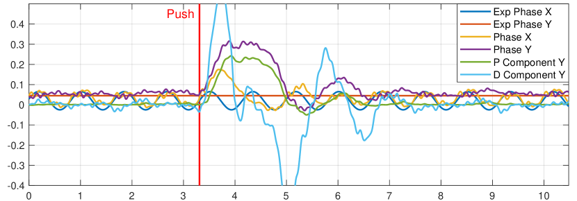
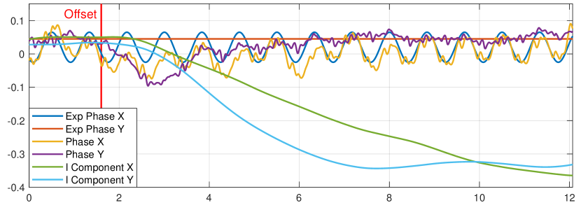
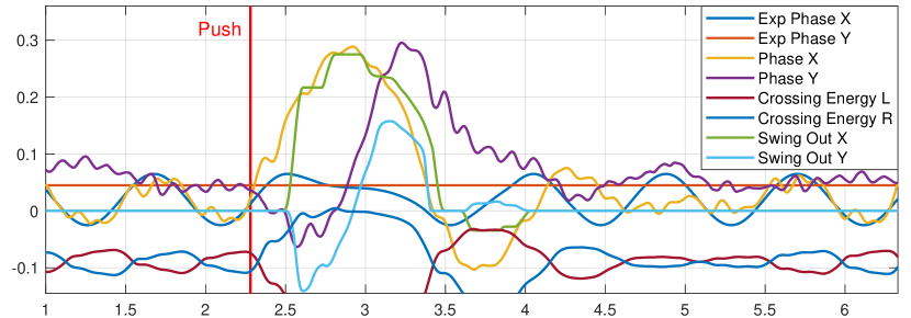
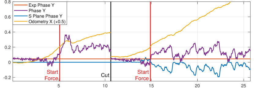
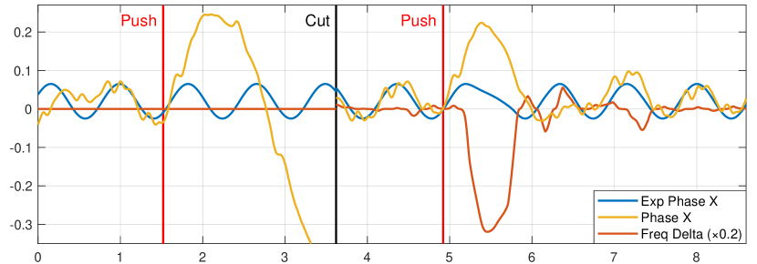
Fig. 4 and Fig. 5 show plots of the tilt phase controller running on a real igus® Humanoid Open Platform. Experiments were performed to isolate and demonstrate the effect of the various corrective actions, in most cases with all other feedback turned off. The physical response of the robot to such disturbances can be seen in an adjoining video.222https://youtu.be/spFqqktZ1s4 In Fig. 4, it can be observed that the tilt phase corresponds closely to the expected waveforms, until a large diagonal push disturbs the robot. The PD activations quickly spike, preventing a forwards fall, and aiding the robot in returning to its expected tilt phase trajectory. Note that when the robot starts returning to upright, the sign of the D feedback changes to dampen the system and prevent excessive overshoot. In Fig. 4, a gait-external offset to the ankle orientations is suddenly applied in software, with only I feedback enabled. Over time, 2D hip shifts and foot tilts are integrated up to negate the effect of the applied offset, and return the robot to nominal walking. In Fig. 4, the robot is made to start walking forwards and then slow down and stop again shortly after. Without the sagittal leaning components the robot falls backwards, but with them the robot leans forwards initially and backwards at the end to add feedforward stability to the walking. In Fig. 4, a large lateral push is applied that puts the robot on a crossing trajectory. Using the counterbalance of its free leg, energy is taken out of the swing, ensuring that the crossing energy does not surpass zero, which would indicate a non-returning trajectory. Note that during the long time spent on the support leg, y components of swing out are used to help prevent sagittal falls.
| Impulse () | 1.2 | 1.5 | 1.8 | 2.0 | 2.2 | 2.4 | 2.6 | 2.8 |
|---|---|---|---|---|---|---|---|---|
| Tilt phase | 20 | 20 | 17 | 16 | 14 | 9 | 7 | 4 |
| Allgeuer [2] | 19 | 20 | 15 | 12 | 11 | 8 | 3 | 4 |
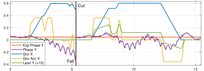
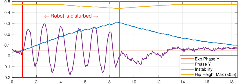
In Fig. 5, a continuous forwards force is applied to the robot during forwards walking that causes the robot to tilt forwards. Without swing ground plane adjustment, the robot tends to walk ‘into the ground’, and gets more stuck than if the swing ground plane is enabled. This is evidenced by the difference in sagittal gait odometry, also plotted. In Fig. 5, lateral pushes are applied to the robot that disrupt its natural walking rhythm. Without timing adjustments, this leads to a lateral fall. With adjustments however, the robot slows down its stepping motion when it detects the disturbance and tries to place its next foot when the lateral tilt is close to zero again. In Fig. 5, the robot is artificially disturbed over multiple seconds to demonstrate an extreme case of how oscillations lead to a higher quantified level of instability, and subsequently a reduction in hip height. In real walking, this is relevant for when the robot gets stuck in a limit cycle of oscillations, a situation that can occur, but is difficult to replicate intentionally. Lowering the hip height increases passive stability and changes the natural frequency of the dynamics of the tilting motions. Both factors often lead to damping of the oscillations.
The tilt phase controller was also evaluated quantitatively in simulation in Gazebo. Maximum forwards walking speed tests were performed over a distance with a run-up. A maximum mean velocity of was achieved, while with [2], was achieved.333https://youtu.be/yY0kpUZpjO4 Sets of 20 pushes in a random direction were also simulated for a robot walking in place, with various different push strengths.444https://youtu.be/6Zfo8Ndt8xQ The number of withstood pushes for each method is shown in Table I. The proposed method achieves clearly better results than [2].
VII Conclusion
Walking does not always require overly complex stabilisation mechanisms to achieve high levels of robustness. In this paper, a feedback controller for robust bipedal walking has been presented that relies solely on measurements from a single 6-axis IMU in the trunk, and is applicable to low-cost robots with noisy sensors, imperfect actuation and limited computing power. No highly tuned or complex physical models are required, and great portability is ensured through the use of dimensionless parameters and configuration constants. The wide variety of corrective actions that are employed cover many different aspects of balanced walking, including both short-term and long-term stability. In summary, although conceptually simple, the tilt phase controller achieves genuinely good results.
References
- [1] P. Kryczka, P. Kormushev, N. Tsagarakis, and D. Caldwell, “Online regeneration of bipedal walking gait optimizing footstep placement and timing,” in Int. Conf. on Intell. Robots and Systems (IROS), 2015.
- [2] P. Allgeuer and S. Behnke, “Omnidirectional bipedal walking with direct fused angle feedback mechanisms,” in Proceedings of 16th Int. Conf. on Humanoid Robots (Humanoids), Cancún, Mexico, 2016.
- [3] NimbRo. (2018, Jul) igus Humanoid Open Platform ROS Software. [Online]. Available: https://github.com/AIS-Bonn/humanoid_op_ros
- [4] P.-B. Wieber, “Trajectory free linear model predictive control for stable walking in the presence of strong perturbations,” in IEEE Int. Conf. on Humanoid Robots (Humanoids), Genova, Italy, 2006.
- [5] S. Kajita, F. Kanehiro, K. Kaneko, K. Fujiwara, K. Harada, K. Yokoi, and H. Hirukawa, “Biped walking pattern generation by using preview control of zero-moment point,” in Int. Conf. on Rob. and Auto., 2003.
- [6] J. Urata, K. Nshiwaki, Y. Nakanishi, K. Okada, S. Kagami, and M. Inaba, “Online decision of foot placement using singular LQ preview regulation,” in IEEE Int. Conf. on Humanoid Robots, 2011.
- [7] S. Feng, X. Xinjilefu, W. Huang, and C. Atkeson, “3D walking based on online optimization,” in Proceedings of 13th IEEE-RAS Int. Conference on Humanoid Robots (Humanoids), Atlanta, USA, 2013.
- [8] R. Tedrake, S. Kuindersma, R. Deits, and K. Miura, “A closed-form solution for real-time ZMP gait generation and feedback stabilization,” in Int. Conf. on Humanoid Robots (Humanoids), Seoul, Korea, 2015.
- [9] S. Kajita, M. Benallegue, R. Cisneros, T. Sakaguchi, S. Nakaoka, M. Morisawa, K. Kaneko, and F. Kanehiro, “Biped walking pattern generation based on spatially quantized dynamics,” in Proceedings of 17th Int. Conf. on Hum. Robots (Humanoids), Birmingham, UK, 2017.
- [10] P. Allgeuer and S. Behnke, “Tilt rotations and the tilt phase space,” in Proceedings of 18th Int. Conf. on Humanoid Robots (Humanoids), Beijing, China, 2018.
- [11] P. Allgeuer and S. Behnke, “Fused Angles: A representation of body orientation for balance,” in IROS Conf., Hamburg, Germany, 2015.
- [12] P. Allgeuer and S. Behnke, “Fused angles and the deficiencies of Euler angles,” in Int. Conf. on Intell. Robots and Systems (IROS), 2018.
- [13] P. Allgeuer and S. Behnke, “Robust sensor fusion for biped robot attitude estimation,” in Proceedings of 14th IEEE-RAS Int. Conference on Humanoid Robotics (Humanoids), Madrid, Spain, 2014.
- [14] M. Missura, “Analytic and learned footstep control for robust bipedal walking,” Ph.D. dissertation, University of Bonn, 2015.