On the Performance of DF-based Power-Line/Visible-Light Communication Systems
Abstract
This paper presents a comprehensive performance analysis of an integrated indoor power line communication (PLC)/visible light communication (VLC) system with the presence of a decode-and-forward (DF) relay. The existing indoor power line networks are used as the backbone for VLCs. The performance of the proposed system is evaluated in terms of the average capacity and the outage probability. A new unified mathematical method is developed for the PLC/VLC system and analytical expressions for the aforementioned performance metrics are derived. Monte Carlo simulations are provided throughout the paper to verify the correctness of the analysis. The results reveal that the performance of the proposed system deteriorates with increasing the end-to-end distance and improves with increasing the relay transmit power. It is also shown that the outage probability of the system under consideration is negatively affected by the vertical distance to user plane.
Index Terms:
Decode-and-forward (DF), power line communications (PLC), signal-to-noise ratio (SNR), visible light communications (VLC).I Introduction and Related Works
Reliable communications can be achieved by integrating different networks such as power line communication (PLC) with visible light communication (VLC) and PLC with wireless communication systems. Such systems have been studied by many researchers and have shown very promising solutions in terms of capacity, security and data rate improvements [1, 2]. Exploiting the existing power line networks in buildings and utility grids makes such networks one of the competitive technologies for broad-band communications in indoor applications. The other technology, which is expected to play an essential role in such applications, is the optical wireless communication (OWC). VLC is one of the indoor OWC technologies which has attracted a considerable attention because of the widespread usage of the LEDs.
Recently, the adoption of other communication technologies for PLC and VLC systems has motivated many researchers to implement different relaying protocols to further enhance the system performance, the most common of which are decode-and-forward (DF), amplify-and-forward (AF), incremental DF and selective DF relaying, see e.g., [3, 4, 5, 6, 7, 8].
The implementation of half duplex time division relaying protocols with indoor PLC applications has been investigated by the authors in [4]. The authors in [9] concluded that the relay deployment in wireless systems is by far more efficient than that in PLC systems. Two-way relaying and one-way relaying were discussed in [3] where the authors reported that there is a significant improvement in system performance by utilizing the former compared to the latter. The authors in [10] investigated the deployment of multi-way relaying in parallel for indoor PLC applications. It was found that the achievable data rates were relatively high compared to those accomplished by single transmission. The study in [1] discussed the hybrid PLC/wireless system performance in the presence of AF relaying where the source of the information simultaneously transmits data via both networks PLC and wireless. It was reported that the integrated PLC/wireless system outperforms the PLC-only and the wireless-only systems. The performance of cooperative free space optics (FSO)-VLC communication system in terms of capacity with a DF relay was investigated in [5]. The FSO link was the backbone of the VLC system and the DF relay was located in-between the two links. It was concluded that this system has high efficiency in terms of data rate. The cooperation between light sources and how it can improve the performance of VLC systems was investigated in [11] where the authors reported that the implementation of DF relaying offers better performance than that of AF relaying.
To the best of the authors knowledge, only few works have studied the performance of cascaded PLC/VLC links in the presence of DF relaying protocols in terms of capacity and outage probability. Therefore, this paper investigates the implementation of DF relaying to connect PLC and VLC links via a DF relay. In the proposed system, the information source first sends the information signal to a DF relay through a PLC link. Secondly, the DF relay decodes and forwards the received signal to the destination node via the VLC channel. The major contribution of this work resides in deriving analytical expressions for the average capacity and the outage probability of the proposed hybrid PLC-VLC DF-based system. Formulating the overall capacity and outage probability of the proposed PLC/VLC system offers the opportunity to examine the effect of various system parameters on the communication performance.
II System Model
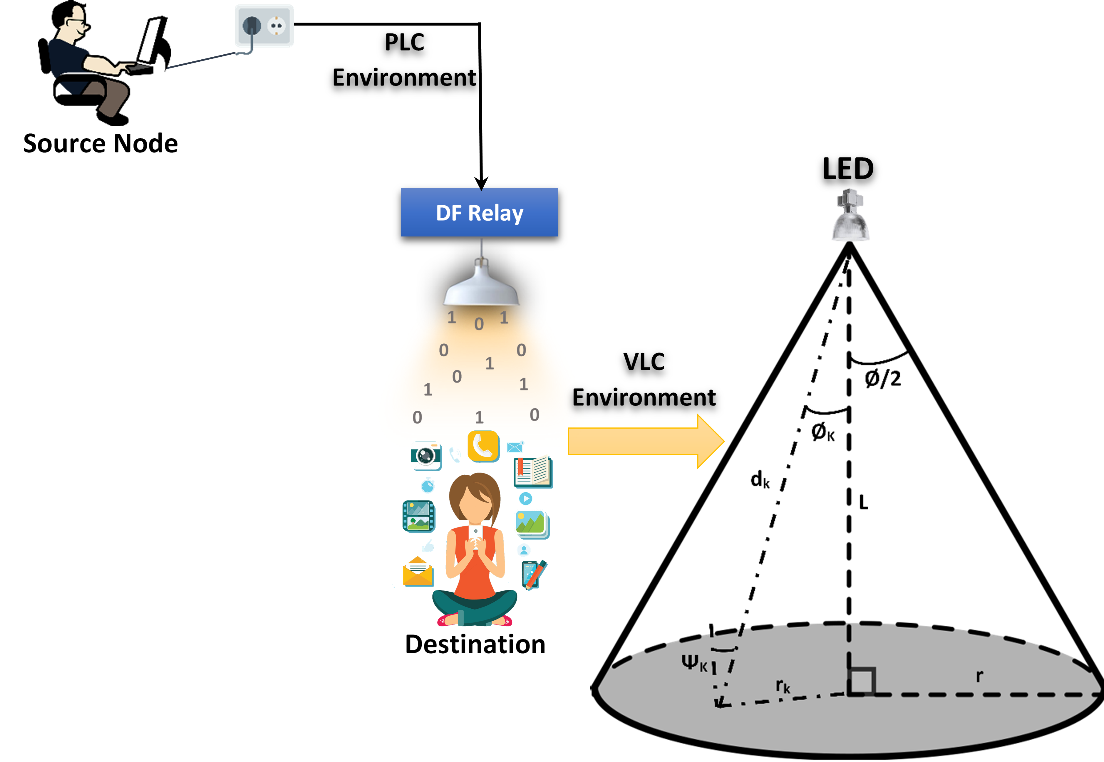
The system model under consideration is shown in Fig. 1 where PLC users can be connected to the network through PLC modems. We assume that the source node and the VLC user are in a different floors. The DF relay receives the data from the source node via the PLC link. The data is then decoded and re-transmitted by the DF relay to the end user through the VLC link. The complex channel gains and represent the source-to-relay, (i.e., the PLC link) and the relay-to-destination, (i.e., the VLC link) channel gains, respectively. Both channels are assumed to be independent and identically distributed. The channel distribution of the PLC link is log-normal distribution [12]. In this study, we consider the line-of-sight (LOS) component of the down-link transmission of the LED only as it represents more than of the total received signal [13]. The LED is located on the ceiling with a vertical distance to the user plane and Euclidean distance to the destination . The VLC channel is subjected to a random distribution which is affected by the uniform distribution of the user‘s location [13]. Because of the nature of the network structure adopted here, it is logical to assume that there is no direct link between the source and destination nodes. It is worth mentioning, for simplicity and without loss of generality, that noise over the two links is assumed to be additive white Gaussian noise (AWGN).
III Performance Analysis
III-A Average Capacity
The instantaneous capacity of the hybrid system is given by the following
| (1) |
where and are the instantaneous capacities of the PLC and VLC links, respectively.
Therefore, each link capacity should be derived in order to find the overall capacity. We start with the PLC link which connects the transmitter with the DF relay and acts as a backhaul to the VLC link. The signal at the relay can be given by
| (2) |
where represents the source transmit power, represents the source-to-relay distance, is the information signal with E[s]=1, is the noise at the relay which is assumed to be complex Gaussian with zero mean and variance , and is the PLC channel attenuation factor given by , where and are constants determined by measurements, is the system operating frequency and denotes the exponent of the attenuation factor [14].
The signal-to-noise ratio (SNR) at the DF relay can be written as follows
| (3) |
Mathematically, we can calculate the average capacity of the PLC link as [14]
| (4) |
where represents the weight factors of the order Hermite polynomial, is the zeros of the same order and
| (5) |
where is the scaling constant and is equal to , and are the log-normal parameters, and
Now we calculate the average capacity of the VLC link. The received signal at the VLC user can be expressed as
| (6) |
where is the information signal with E[s]=1, is the relay transmit power and represents the destination noise with zero mean and variance .
The SNR at the destination can be written as
| (7) |
The average capacity of the VLC link is calculated as
| (8) |
where is the probability density function (PDF) , and .
Considering the random distribution mentioned above for the VLC link and the Lambertian radiation pattern for LED light emission, the VLC channel gain can be written as
| (9) |
where is the detection area of the detector, , represents the the optical filter gain, denotes the optical concentration gain, the responsivity of the photo-detector is represented by , is the total angel of the LED, , and is the order of the Lambertian radiation pattern which is given by
| (10) |
where denotes the semi-angle of the LED.
To simplify our analysis, let us assume that . Hence, (9) can be rewritten as
| (11) |
It is assumed that the location of the users is uniformly distributed with PDF given as
| (12) |
The PDF of the un-ordered channel gain of the VLC link can be driven using the change-of-variable method used in [5] as follows
| (13) |
We can now derive the PDF of the VLC channel gain given by
| (14) |
where is the maximum cell radius of the LOS.
The PDF of can now be obtained as
| (15) |
| (16) |
| (17) |
III-B Outage Probability
The outage probability is simply defined as the probability that the instantaneous SNR of system is less than a certain threshold value, , and is given as
| (18) |
The end-to-end outage probability for the proposed system can be written as
| (19) |
where is outage probability of the first link and is the outage probability of the second link.
The cumulative density function (CDF) of each link represents the outage probability of that link. Therefore, the outage probability of the PLC and VLC links can be calculated as
| (20) |
and
| (21) |
IV Numerical Results
This section presents some numerical results of the derived expressions above. The system parameters under consideration are, unless indicated otherwise, as follows: operating frequency of the system kHz, , , , , the input power W, W, input SNR is 10dB, m, dB, A/W, m, m and [15].
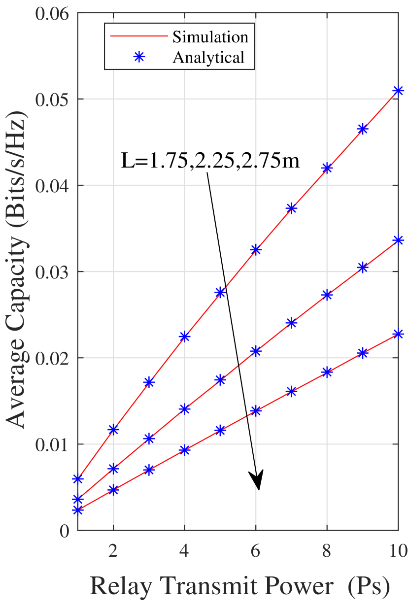
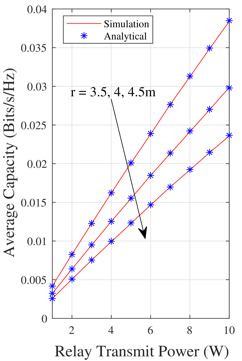
The effect of the relay transmit power and the vertical distance to the user plane on the performance of the proposed hybrid system is presented in Fig. 3. It is clear that the analytical results, obtained from (17), are in perfect agreement with the simulation ones. As it can be seen, the performance improves as the relay transmit power increases and/or the vertical distance of the LED decreases. Fig. 3 illustrates the impact of the maximum cell radius of the LOS on the system performance. It is noticeable that the performance of the system has a noticeable improvement when the maximum cell radius of the LOS decreases, particularly for the high values of the relay transmit power.
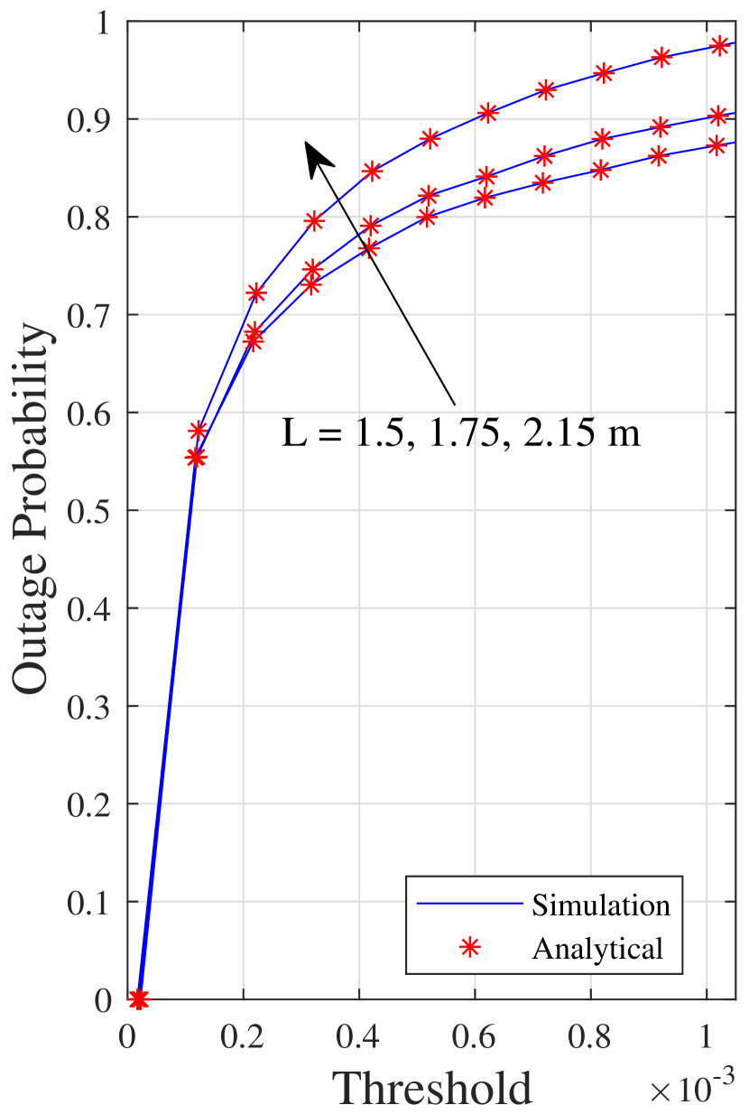
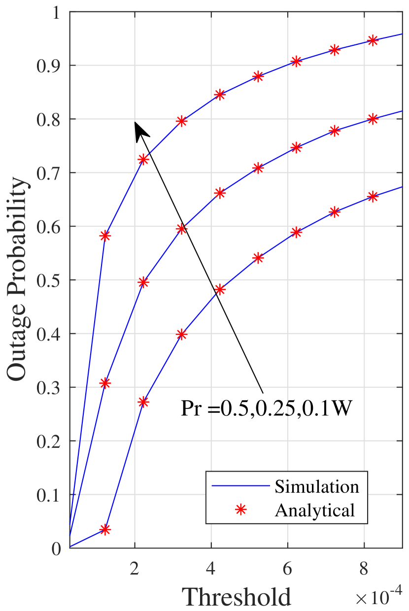
The outage probability of the proposed system is plotted in Figs. 5 and 5 versus the threshold for different values of the height of the LED and the relay transmit power, respectively. Looking at both figures, we can see that the performance is considerably affected by these two factors as it degrades when the relay transmit power increases and the vertical distance decreases. On the other hand, it increases when the relay transmit power declines and the height of the LED increases.
V Conclusions
This paper analyzed the performance of the hybrid PLC/VLC system in terms of the average capacity and outage probability for which analytical expressions were derived and then verified by Monte Carlo simulations. We investigated the effect of different system parameters on the performance of the proposed system. The results revealed that the performance of the proposed hybrid system is affected by various parameters, such as the relay transmit power, the height of the LED and the maximum cell radius of the LOS. It is worth pointing out that the use of such hybrid systems can provide better mobility to the end user than that provided by the PLC-only system.
References
- [1] L. de M. B. A. Dib, V. Fernandes, M. de L. Filomeno, and M. V. Ribeiro, “Hybrid PLC/wireless communication for smart grids and internet of things applications,” IEEE Internet Things. J, vol. PP, no. 99, pp. 1–1, 2017.
- [2] T. Komine and M. Nakagawa, “Integrated system of white LED visible-light communication and power-line communication,” IEEE Trans. Consum. Electron., vol. 49, pp. 71–79, Feb. 2003.
- [3] B. Tan and J. Thompson, “Relay transmission protocols for in-door powerline communications networks,” in IEEE Int. Conf. Commun.(ICC), pp. 1–5, June. 2011.
- [4] S. D’Alessandro and A. M. Tonello, “On rate improvements and power saving with opportunistic relaying in home power line networks,” EURASIP J. Advances. Signal Process., vol. 2012, p. 194, Sept. 2012.
- [5] A. Gupta, N. Sharma, P. Garg, and M. S. Alouini, “Cascaded FSO-VLC communication system,” IEEE Wireless Commun. Lett., vol. 6, pp. 810–813, Dec. 2017.
- [6] K. M. Rabie and B. Adebisi, “Enhanced amplify-and-forward relaying in non-gaussian plc networks,” IEEE Access, vol. 5, pp. 4087–4094, 2017.
- [7] K. M. Rabie, B. Adebisi, H. Gacanin, G. Nauryzbayev, and A. Ikpehai, “Performance evaluation of multi-hop relaying over non-Gaussian PLC channels,” J. Commun. Netw., vol. 19, pp. 531–538, Oct. 2017.
- [8] K. M. Rabie, B. Adebisi, H. Gacanin, and S. Yarkan, “Energy-per-bit performance analysis of relay-assisted power line communication systems,” IEEE Trans. Green Commun. Networking, vol. 2, pp. 360–368, Jun. 2018.
- [9] H. Zou, A. Chowdhery, S. Jagannathan, J. M. Cioffi, and J. L. Masson, “Multi-user joint subchannel and power resource-allocation for powerline relay networks,” in IEEE Int. Conf. Commun.(ICC), pp. 1–5, Jun. 2009.
- [10] M. Noori and L. Lampe, “Multi-way relaying for cooperative indoor power line communications,” IET Commun., vol. 10, no. 1, pp. 72–80, 2016.
- [11] O. Narmanlioglu, R. C. Kizilirmak, and M. Uysal, “Relay-assisted OFDM-based visible light communications over multipath channels,” in 2015 17th Int. Conf. Transparent Optical Netwr. (ICTON), pp. 1–4, Jul. 2015.
- [12] A. M. Tonello, F. Versolatto, B. Bejar, and S. Zazo, “A fitting algorithm for random modeling the PLC channel,” IEEE Trans. Power Del., vol. 27, pp. 1477–1484, Jul. 2012.
- [13] L. Zeng, D. C. O’Brien, H. L. Minh, G. E. Faulkner, K. Lee, D. Jung, Y. Oh, and E. T. Won, “High data rate multiple input multiple output MIMO optical wireless communications using white led lighting,” IEEE Journal Sel. Areas Commun., vol. 27, pp. 1654–1662, December 2009.
- [14] W. Gheth, K. M. Rabie, B. Adebisi, M. Ijaz, G. Harris, and A. Alfitouri, “Hybrid power-line/wireless communication systems for indoor applications,” in 2018 11th Int. Symp. Commun. Syst., Netw. and Digit. Signal Process. (CSNDSP), pp. 1–6, July 2018.
- [15] W. Gheth, K. M. Rabie, B. Adebisi, M. Ijaz, and G. Harris, “Performance analysis of integrated power-line/visible-light communication systems with af relaying,” in IEEE Global Commun. Conf. (GLOBECOM), 2018.