Contributed equally to this work \altaffiliationContributed equally to this work \alsoaffiliationDipartimento di Fisica e Chimica, Universitá degli Studi di Palermo, Via Archirafi 36, I-90123, Palermo, Italy \alsoaffiliationCenter for Computational Quantum Physics (CCQ), The Flatiron Institute, 162 Fifth avenue, New York NY 10010.
Cavity control of Excitons in two dimensional Materials
Abstract
We propose a robust and efficient way of controlling the optical spectra of two-dimensional materials and van der Waals heterostructures by quantum cavity embedding. The cavity light-matter coupling leads to the formation of exciton-polaritons, a superposition of photons and excitons. Our first principles study demonstrates a reordering and mixing of bright and dark excitons spectral features and in the case of a type II van-der-Waals heterostructure an inversion of intra and interlayer excitonic resonances. We further show that the cavity light-matter coupling strongly depends on the dielectric environment and can be controlled by encapsulating the active 2D crystal in another dielectric material. Our theoretical calculations are based on a newly developed non-perturbative many-body framework to solve the coupled electron-photon Schrödinger equation in a quantum-electrodynamical extension of the Bethe-Salpeter approach. This approach enables the ab-initio simulations of exciton-polariton states and their dispersion from weak to strong cavity light-matter coupling regimes. Our method is then extended to treat van der Waals heterostructures and encapsulated 2D materials using a simplified Mott-Wannier description of the excitons that can be applied to very large systems beyond reach for fully ab-initio approaches.
Keywords: Exciton-polaritons, Quantum Cavity, QED, Transition Metal Dichalcogenides, Bethe-Salpeter equation, First-principles.
Introduction
Excitons dominate the optical properties of two-dimensional semiconductors. Single layers of Transition Metal Dichalcogenides (TMDs) have been under intense investigation for their excitonic properties 1, 2, 3. Their weak electronic screening 4, 5, a consequence of the reduced dimensionality, leads to the formation of strongly bound bright and dark excitons which play a fundamental role in a large variety of optoelectronic, spintronic and valleytronic properties 6. Furthermore, single layers of TMDs can be stacked in multilayer heterostructures allowing for device engineering with a high degree of freedom 7, 8, 9. Among other designs, bilayers of TMDs with a type II band alignment enables the creation of interlayer excitons, bound electron-hole pairs where the charges are physically confined in two different layers, which show a great potential in photovoltaic applications 10, 11
Due to their strong coupling to electromagnetic radiation, TMD excitons represent ideal candidates to study strong light-matter coupling in optical cavities 12, 13, 14, 15, 16. In an optical resonator, excitons interact with the quanta of light, generated by the spatial confinement of the cavity, resulting in the formation of new hybrid states with partial matter and partial light character, the exciton-polaritons 17, 18, 19. These states are inherently different from the bare excitonic states in the material and therefore a variety of novel phenomena can be expected. Envisioned examples comprise new topological phases 20, light-induced superconductivity 21, exciton-polariton condensates 22 and superradiance from exciton insulators23.
Here, we present a first-principles theoretical framework, referred to as
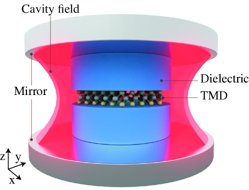
quantum-electrodynamical Bethe-Salpeter Equation (QED-BSE), designed to describe the coupling of excitonic states in solid state materials embedded in a quantum optical cavity. Our approach goes beyond a simple model Hamiltonian description of exciton polariton by providing a quantitative description of exciton-polariton directly comparable to the experiments. The method requires the exact diagonalization of the exciton-photon equation obtained by extending the widely used many-body Bethe-Salpeter (BSE) formalism 24, 25, 26, 27 to QED, under the approximation that the electron-electron interaction is not affected by the photon dressing. This method represents an alternative to the recently proposed quantum-electrodynamical density functional theory28, 29, 30, 31, 17, 32, 18, 19, 33, the latter describing the cavity mediated electron-photon interaction through effective exchange-correlation functionals of the electron and photon densities and currents. Our current method can be used as a starting point to determine such functionals as done in the past for describing the many-body excitonic properties within time-dependent (current) density functional theory27. In this work we demonstrate that by embedding a two-dimensional crystal in a cavity as sketched in Fig. 1, excitonic optical activity and energetic ordering can be controlled through cavity size, light-matter coupling strength and encapsulation in a dielectric material.
While the reordering of excitonic resonances has been qualitatively demonstrated in the case of molecular systems by means of model hamiltonians consisting of coupled oscillators for the photonic and excitonic fields34, 35, here we aim to quantitatively demonstrate similar effects in the context of extended system.
Within dipolar selection rules there are bright excitons (BE), i.e. accessible as direct transition from the groundstate upon photon absorption, and dark excitons (DE) which are instead not accessible in linear optical spectroscopy 36. The difficulty to access DE with standard optical spectroscopy poses a challenge for their detection and recent experimental and theoretical works have proposed sophisticated techniques to access them in TMDs 37, 38. Here we address and control the activity of symmetry-forbidden DE through the coupling of the TMD crystal with a quantum cavity which allows direct transitions from the groundstate.
More complex types of excitons can be obtained if different monolayers of TMDs with a type II band alignment are stacked together in a van der Waals heterostructure (vdWH)39. In particular
these type II heterostructures can host excitons where the electron and the hole are localized in different layers, interlayer excitons, in addition to excitons localized on a single layer, the intralayer ones. Here we show how the coupling to an optical cavity can be used to tune the order of the spectral resonances of the different types of excitons, providing a further knob for the design of optical devices based on vdWHs.
We also show that the ab initio QED-BSE results can be described by an alternative approach based on the Mott-Wannier model, which we refer to as MW-QED, represents a computationally inexpensive method able to simplify the QED-BSE approach by simplifying the description of excitons40, 41, 42. The MW-QED accurately reproduces the results of the QED-BSE opening the way to the modeling of more complex systems, such as 2D heterostructures, Moiré patterned twisted bilayer systems and others, in optical cavities.
Finally we use the MW-QED to characterize the effect produced by a dielectric on the polaritonic spectrum of a single layer of TMD.
Theoretical Framework
The electronic structure of a strongly coupled light-matter system in a cavity requires a non-perturbative treatment of the electron-photon interaction. Fundamentally, light-matter coupling is described by quantum-electrodynamics where the many-body electron and photon state is described by a combined Hamiltonian. Specializing this Hamiltonian to the case of a a single cavity mode of frequency and long-wavelength (dipolar) electron-photon coupling we obtain the first-principles Hamiltonian for perfect loss-less cavity in velocity gauge:
| (1) |
where and are the photon creation and annihilation operators respectively, the many-body electronic Hamiltonian, the electronic creation and annihilation operators (with band indices and wavevectors in the first Brillouin zone), the single particle momentum operator, the number of electrons, the polarization of the photon and is the vector potential amplitude. Since the coupling of photons to the electronic structure occurs via the creation/annihilation of neutral electron-hole pairs, it is natural to approximate the eigenstates of the many-body electronic Hamiltonian by its excitonic eigenstates, i.e. . Within this assumption we can accurately describe a regime where the concentration of excitons is low enough to neglect exciton-exciton interaction, which is the case for non-pumped cavities. Under the approximation that the electron-hole Coulomb interaction that binds the exciton is not affected by the photons in the cavity, i.e. the screened Coulomb interaction is not dressed by the cavity photons, the QED Hamiltonian can be expanded in the excitonic basis as follows:
| (2) |
where are excitonic matrix elements of the bilinear dipole electron-photon coupling and are single particle Bloch functions. In this framework the excitonic states can be expressed as a linear combination of singly excited electronic determinants, where the coefficients of the linear combination are given by the solution of the BSE 25, 26, 27, with the BSE coefficients, or envelope functions and and indices running over conduction and valence bands respectively. The electronic groundstate instead is assumed to be a single determinant of only valence states and we define .
In this work we consider the non-dispersive (momentum independent) excitonic states localized around the K-points of the Brillouin zone of the TMD, which are the most relevant for the optoelectronic properties of TMDs. These excitonic states occur in two spin-orthogonal non-hydrogenic series, each of which is accurately described by a spin-independent two-band BSE, where only a single valence and a single conduction band are taken into account 42. With this simplification the matrix elements appearing in Eq. (2) have one of the two following structures:
| (3) | ||||
| (4) |
The matrix elements in Eq. (3) are those that dictate the dark/bright nature of the excitonic states. Those in Eq. (4), instead, are mixing the character of the excitonic states so that bright to dark or dark to bright transitions can occur.
Below we show first principles results for MoS2 obtained by first solving the BSE with the GPAW code 43, 44 (see supplementary material for calculation details) and subsequently diagonalizing the QED Hamiltonian of Eq. (2) in a mixed exciton-photon product state basis , where are the eigenfunctions of the photonic harmonic oscillator. We then extract energies () and corresponding eigenfunctions () for the exciton-polariton eigenstates. As for the photonic part, we consider the first non-zero photon mode () with out-of-plane wavevector and in-plane electric field which is able to couple to the MoS2 in-plane excitonic dipole. For our quasi-2D cavity configuration the vector potential amplitude is frequency independent, unlike in the 3D case, indeed , where S is the in-plane area of the cavity. Furthermore we stress that the single mode approximation is valid for polaritons with energies lower than the energy of the second photon mode (). In the supplementary material we show that including higher energy modes does not change the conclusions discussed below. We note that diagonalization of Eq. (2) is equivalent to solving a CI-singles in the presence of a photon mode. In particular, excited states of the material are expressed as linear combinations of singly excited determinants starting from the ground state and subsequently coupled, through the diagonalization, to the photonic degrees of freedom.
Results
In order to visualize the experimentally measurable exciton-polariton dispersion, we calculate the matter component of the full optical response applying linear response theory on the polaritonic states33, 19:
| (5) |
where and is a small artificial imaginary broadening. Such a quantity represents the independent particle polarizability of the polariton to a weak external field coupling with the matter component. An equivalent quantity can be also formulated to investigate the photonic counterpart of the polariton. Comparison between the matter and photon spectral functions is presented in Fig. S5 of the Supporting Information.
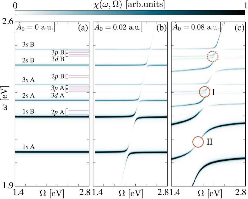
The formation of exciton-polaritons results in a richer optical response as compared to the bare excitonic response. In Fig. 2 we show the cavity polariton spectrum of MoS2 as a function of mode energy and for different coupling strength . Here the coupling strength arises from a microscopical definition while in practice it can be controlled by the cavity geometry and manufacturing parameters 45.
Without any electron-photon coupling (), the spectrum features only the bare BEs as shown in Fig. 2(a), characterized by the common spin-orbit split A and B exciton series (see supplementary material)46. Bound excitons in TMDs have atom like spherical symmetries, following the usual pattern of angular momentum quantum numbers and consequently are subject to atomic like selection rules 37. Only excitons with -type symmetry are accessible from the ground state through direct absorption of photons. The and -type excitons instead can be classified as DEs and are indicated with lines in Fig. 2(a) for reference.
In the weaker coupling regime (c.f. Fig. 2(b)) the formation of an exciton-polariton is accompanied by the characteristic appearance of avoided crossing in the energy dispersion, which results from the hybridization between the linear dispersing photon branch and the non-dispersive exciton branches. For a given cavity frequency within the hybridisation region, this is detectable as a splitting of the exciton peak into two separate peaks – the Rabi splitting. The formation of lower and upper polariton branches results in a reordering of the energy of bright and dark excitonic resonances which can be of technological relevance for stabilizing long-lived dark excitonic states.
For the stronger coupling (c.f. Fig. 2(c)), the interaction between the cavity photon and the DE results in the appearance of new spectral features marked by circles in the figure. Specifically, we can identify additional splittings (I)/interruptions (II) signature of a cavity induced optical modulation. It is important to mention that the mixing between bright and dark excitons discussed here is possible only for DE forbidden by symmetry of the wave function37. Different kind of dark excitons like the ones originating from spin-selection rules or beyond dipole selection rules are not discussed in this work47. In this stronger coupling regime () we performed calculations also for different TMDs (MoSe2, WS2 and WSe2, see supplementary material) observing qualitatively equivalent features. It is worth noting that for the most bound exciton of WS2 we obtain a Rabi splitting of meV in line with experimental values measured by Flatten et al. ( meV)12. While it is hard to asses the exact coupling conditions under which the experiment has been performed, this comparison shows that the coupling values used here are on the lower end of the experimentally accessible values. The coupling values used in the results are also in line with the typical sizes of the cavity used in the experiments, which are in the - range. In particular, using the definition presented above, a coupling value of a.u. and an electron density of 0.114 el/Å2, like in the case of MoS2, corresponds to a cavity area of of about .
Further insight into the structure of these dark polaritons is provided by the analysis shown in Fig. 3. The panels quantify the contribution of the different excitonic states to the optically active polariton states at specific cavity energy along the dispersion branches shown in Fig. 2. The decomposition of the polariton in Fig. 3(a), which is a zoom-in of the circle (I) in Fig. 2(c), shows that it is predominantly the DE that is creating the polaritonic eigenstate. However, it is only because of the photon mediated coupling to the BE that the DE acquires a finite optical cross section. More specifically the coupling between the two states happens within the photon sector meaning that there is not an actual absorption or emission of photons in the mixing process but rather both an absorption and subsequent emission (or vice versa) to and from a virtual -like state in the photon sector. Due to the hydrogenic-like selection rules, there is no possible excitation/relaxation path between a bright -like state and dark -like, i.e. ”d”-like states cannot function as virtual states, one do not get a finite oscillator strength. As demonstrated by the insets in Fig. 3(a) both the lower and upper branch of the DE polariton have a similar composition.
While Fig. 3(a) illustrates how the cavity coupling reveals hidden (dark) states of a material, we observe another peculiarity in the polariton dispersion in Fig. 3(b), which corresponds to the circle (II) in Fig. 2(c). Through the cavity we can induce a quench of the optical activity within the polariton branch connecting two BEs, i.e. the spectral response vanishes completely between two consecutive BE lines. In this case, such a dimming of the polariton branch is not originating from the contribution of DE states, but instead is the result of an interesting destructive interference between the optical transition amplitudes from the exciton lines connected by the photon branch. The destructive interference is demonstrated in the inset of Fig. 3(b) which reports the real and imaginary part of the transition amplitude from the groundstate to the A and B excitonic states, the states that make up most of the polariton state.

The QED-BSE method illustrated above requires considerable computational effort and it is therefore limited to few layers of lattice matched (commensurate) TMDs. The polaritonic physics can be well reproduced by replacing the BSE part in the QED-BSE with the Mott-Wannier (MW) equation, hence considerably reducing the computational cost and more importantly giving access to exciton-polariton physics in more complex materials such as encapsulated 2D crystals and van-der-Waals heterostructures. In this approach the bound excitons are described by an hydrogen like Schrödinger equation that provides the exciton envelope functions and hence allows the evaluation of the exciton-dipole matrix elements of the QED-BSE approach as explained in the supporting information.
We apply the MW-QED to calculate the optical response of a vdWH consisting of MoS2 and WS2 bilayer. MoS2 and WS2 form a type-II heterostructure where the band edges of the two materials are aligned in a staggered fashion and which can host interlayer excitons along with intralayer ones in each of the two layers 39, 48. For this particular bilayer choice, because of quasi-commensurability of the lattice of MoS2 and WS2, the QED-BSE has been used to further confirm the validity of the QED-MW presented in the following. However, for more general non-commensurate vdWHs the only feasible approach for simulating exciton-polariton properties is the QED-MW one. The cavity frequency dependent optical response of such a structure for the most highly bound 1s intra- and inter-layer excitons is reported in Fig. 4. Including higher lying excitons does not affect the results presented here since the corresponding spectral features would appear in a higher energy window. The use of norm-conserving PAW-setups are needed to obtain the correct energy level alignment. Details on the method used to calculate the uncoupled excitonic resonances are discussed in the supplementary.
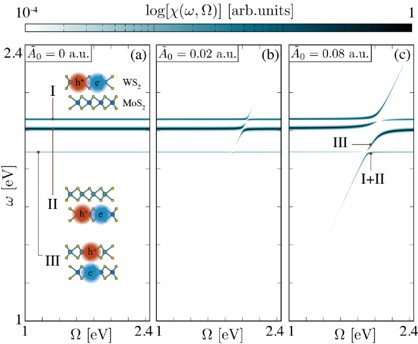
Fig. 4(a) shows the optical spectrum of the vdWH without coupling with the cavity mode. Here, as indicated by the cartoons, the lower energy non-dispersive spectral line represents the optical transitions to the interlayer exciton whereas the higher energy ones are the transition to the intralayer excitons. The oscillator strength of the former is two order of magnitude lower than the one of the intralayer excitons, a direct consequence of the spatial separation of the bound electron-hole pair, justifying the weaker brightness observed in the spectrum. In Fig. 4 the coupling with the cavity mode is switched on and the typical polaritonic branches appear with a sizable Rabi splitting for the intralayer and barely noticeable one for the interlayer one. The difference in Rabi splitting is, once again, a consequence of the weak interlayer exciton-light coupling. Similarly to the case of monolayer MoS2 shown in Fig. 3(b) the interference between the transition to the two intralayer excitons results in a vanishing polariton branch. In the calculations, such an interference arises from the fact that the exciton wavefunctions of the two intralayer excitons appear with the same phase. While it is unsure whether this can be directly realized in experiment because any possible mechanism of dephasing would destroy the effect, one could potentially realize this by using external lasers to fix the relative phase of the different intralayer excitons. Finally, in the stronger coupling regime, shown in Fig. 4(c), the optical response is drastically modified and even the Rabi splitting of the interlayer exciton line is now appreciable. More interestingly, a similar analysis of the polaritonic wavefunctions as the one discussed for Fig. 3(c) shows that the energetic ordering of the transitions to intra and interlayer excitons is modified, as indicated in the panel. In particular the lower polariton branch at transition energies lower than the interlayer exciton resonance has now a non-negligible intralayer exciton composition. We stress that the reordering of the excitonic resonances is possible because of the different light-exciton coupling strength for the different types of excitons. From a practical point of view, the relative light-matter coupling strength for inter and intra-layer excitons can be controlled by (i) bulding active vdW-bilayers out of monolayers with different thicknesses and dielectric properties and (ii) choosing a different embedding material to change the dielectric environment of the cavity. For example a higher coupling strength for the interlayer excitons can be achieved in a vdW-bilayer made of crystals with a lower thickness and lower dielectric screening, whereas a lower coupling strength can be obtained choosing an embedding material with a higher dielectric function. This calculations show the potential of cavity engineering for the optical design of functional devices where either intra-layer or inter-layer excitons can be excited on demand.
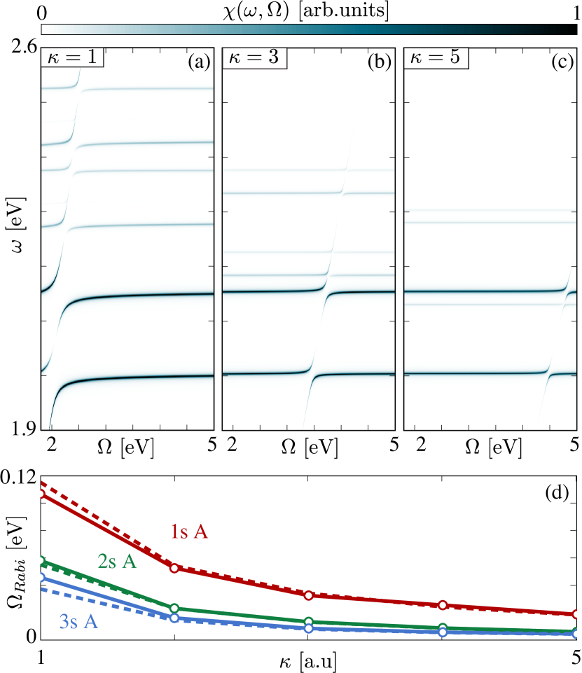
The MW-QED also provides a computationally inexpensive way of assessing the effect of embedding an active 2D materials in a bulk dielectric 42 (as sketched in Fig. 1). The effect of the dielectric environment is accounted for in the MW description through its bulk dielectric constant , c.f. refs. 42, 49 and supplementary material for a detailed description of the method. The effect of environmental screening is threefold: (i) extra-screening of the electron-hole Coulomb interaction, (ii) renormalized photon dispersion () which now propagates in dielectric medium and (iii) by renormalizing the effective vector potential amplitude of the cavity 40.
In Fig. 5(a) we show the polariton dispersion of MoS2 for fixed coupling strength and for various values of dielectric constants for the substrate material . The most striking feature is the change in the slope of the photon line due to the propagation in the cavity dielectric. This shifts the position of the polariton resonances. Furthermore, due to the change of the screened Coulomb interaction, the higher lying excitons are squeezed in energy towards the first excitonic state (cf. supplementary material). Fig. 5(c) shows the dependence of the Rabi-splitting of the first three BEs ( of the A series) as a function of the dielectric constant of the encapsulating material. We compare the splitting of the calculated dispersion with the Rabi splitting of the corresponding Jaynes-Cummings model where only two levels at a time (the groundstate and one of the excitons) are taken into account. Notably, only for small dielectric constants there are deviations from Jaynes-Cummings splitting indicating that for larger effective couplings the two level approximation breaks down.
Conclusion
The QED-BSE formalism we presented here is a first principles approach to the properties of polaritons in optical cavities. We demostrate how it gives rise to complex polaritons dispersions, where hybridizations of polaritons manifest in features originating from DE. We also show how polaritonic interference could result in transparency and could be possibly achieved through laser control. We illustrate how the Mott-Wannier model for bound excitons can be used to obtain the relevant dipole matrix elements that enter the QED equations and thus provide a readily applicable method to compute such polariton properties. This method can be extended to account for the dielectric screening of materials inside the cavity which gives access to a large variety of van-der-Waals layered systems. In particular in the case of a type II vdWH, we demonstrate the possibility of engineering cavity-matter coupling and change the relative energy ordering of intra- and inter-layer excitons. The QED-BSE and MW model presented here are the first ab-initio methods aimed at the design, understanding and control of the optoelectronic properties of materials embedded in quantum cavities.
1 Acknowledgements
We are grateful for helpful discussions with Ch. Schäfer, M. Sentef and M. Ruggenthaler. S. L. acknowledges support from the Alexander von Humboldt foundation. We further acknowledge financial support from the European Research Council(ERC-2015-AdG-694097). The Flatiron Institute is a division of the Simons Foundation.
Supporting Information Available: It contains extensive computational details, convergence tests with respect to the number of excitonic states, number of photons and number of cavity modes included in the calculation, details about the Mott-Wannier methodology and a comparison between the matter and photon spectral functions. This material is available free of charge via the Internet at http://pubs.acs.org.
References
- Manzeli et al. 2017 Manzeli, S.; Ovchinnikov, D.; Pasquier, D.; Yazyev, O. V.; Kis, A. Nat. Rev. Mater. 2017, 2, 17033
- Wang et al. 2018 Wang, G.; Chernikov, A.; Glazov, M. M.; Heinz, T. F.; Marie, X.; Amand, T.; Urbaszek, B. Rev. Mod. Phys. 2018, 90, 021001
- Ugeda et al. 2014 Ugeda, M. M.; Bradley, A. J.; Shi, S.-F.; da Jornada, F. H.; Zhang, Y.; Qiu, D. Y.; Ruan, W.; Mo, S.-K.; Hussain, Z.; Shen, Z.-X. et al. Nat. Mater. 2014, 13, 1091
- Ramasubramaniam 2012 Ramasubramaniam, A. Phys. Rev. B 2012, 86, 115409
- Cudazzo et al. 2011 Cudazzo, P.; Tokatly, I. V.; Rubio, A. Phys. Rev. B 2011, 84, 085406
- Schaibley et al. 2016 Schaibley, J. R.; Yu, H.; Clark, G.; Rivera, P.; Ross, J. S.; Seyler, K. L.; Yao, W.; Xu, X. Nat. Rev. Mater. 2016, 1, 16055
- Kim et al. 2017 Kim, J.; Jin, C.; Chen, B.; Cai, H.; Zhao, T.; Lee, P.; Kahn, S.; Watanabe, K.; Taniguchi, T.; Tongay, S. et al. Science Adv. 2017, 3
- Gao et al. 2012 Gao, G.; Gao, W.; Cannuccia, E.; Taha-Tijerina, J.; Balicas, L.; Mathkar, A.; Narayanan, T. N.; Liu, Z.; Gupta, B. K.; Peng, J. et al. Nano Lett. 2012, 12, 3518–3525
- Geim and Grigorieva 2013 Geim, A. K.; Grigorieva, I. V. Nature 2013, 499, 419
- Hong et al. 2014 Hong, X.; Kim, J.; Shi, S.-F.; Zhang, Y.; Jin, C.; Sun, Y.; Tongay, S.; Wu, J.; Zhang, Y.; Wang, F. Nature nanotechnology 2014, 9, 682
- Jin et al. 2018 Jin, C.; Ma, E. Y.; Karni, O.; Regan, E. C.; Wang, F.; Heinz, T. F. Nature nanotechnology 2018, 13, 994
- Flatten et al. 2016 Flatten, L. C.; He, Z.; Coles, D. M.; Trichet, A. A. P.; Powell, A. W.; Taylor, R. A.; Warner, J. H.; Smith, J. M. Sci. Rep. 2016, 6, 33134
- Chervy et al. 2018 Chervy, T.; Azzini, S.; Lorchat, E.; Wang, S.; Gorodetski, Y.; Hutchison, J. A.; Berciaud, S.; Ebbesen, T. W.; Genet, C. ACS Photonics 2018, 5, 1281–1287
- Slootsky et al. 2014 Slootsky, M.; Liu, X.; Menon, V. M.; Forrest, S. R. Phys. Rev. Lett. 2014, 112, 076401
- Liu et al. 2014 Liu, X.; Galfsky, T.; Sun, Z.; Xia, F.; Lin, E.-c.; Lee, Y.-H.; Kéna-Cohen, S.; Menon, V. M. Nat. Photonics 2014, 9, 30
- Sun et al. 2017 Sun, Z.; Gu, J.; Ghazaryan, A.; Shotan, Z.; Considine, C. R.; Dollar, M.; Chakraborty, B.; Liu, X.; Ghaemi, P.; Kéna-Cohen, S. et al. Nat. Photonics 2017, 11, 491
- Flick et al. 2017 Flick, J.; Ruggenthaler, M.; Appel, H.; Rubio, A. Proc. Nat. Ac. Sci. 2017,
- Flick et al. 2018 Flick, J.; Schäfer, C.; Ruggenthaler, M.; Appel, H.; Rubio, A. ACS Photonics 2018, 5, 992–1005
- Ruggenthaler et al. 2018 Ruggenthaler, M.; Tancogne-Dejean, N.; Flick, J.; Appel, H.; Rubio, A. Nat. Rev. Chem. 2018, 2, 0118
- Sheikhan et al. 2016 Sheikhan, A.; Brennecke, F.; Kollath, C. Phys. Rev. A 2016, 94, 061603
- Sentef et al. 2018 Sentef, M. A.; Ruggenthaler, M.; Rubio, A. Science Advances 2018, 4, eaau6969
- Byrnes et al. 2014 Byrnes, T.; Kim, N. Y.; Yamamoto, Y. Nat. Phys. 2014, 10, 803
- Mazza and Georges 2019 Mazza, G.; Georges, A. Physical Review Letters 2019, 122, 017401
- Salpeter and Bethe 1951 Salpeter, E. E.; Bethe, H. A. Phys. Rev. 1951, 84, 1232–1242
- Rohlfing and Louie 1998 Rohlfing, M.; Louie, S. G. Phys. Rev. Lett. 1998, 81, 2312–2315
- Rohlfing and Louie 2000 Rohlfing, M.; Louie, S. G. Phys. Rev. B 2000, 62, 4927–4944
- Onida et al. 2002 Onida, G.; Reining, L.; Rubio, A. Rev. Mod. Phys. 2002, 74, 601–659
- Tokatly 2013 Tokatly, I. V. Phys. Rev. Lett. 2013, 110, 233001
- Ruggenthaler et al. 2014 Ruggenthaler, M.; Flick, J.; Pellegrini, C.; Appel, H.; Tokatly, I. V.; Rubio, A. Phys. Rev. A 2014, 90, 012508
- Pellegrini et al. 2015 Pellegrini, C.; Flick, J.; Tokatly, I. V.; Appel, H.; Rubio, A. Phys. Rev. Lett. 2015, 115, 093001
- Flick et al. 2015 Flick, J.; Ruggenthaler, M.; Appel, H.; Rubio, A. Proc. Nat. Ac. Sci. 2015, 112, 15285–15290
- Rokaj et al. 2018 Rokaj, V.; Welakuh, D. M.; Ruggenthaler, M.; Rubio, A. J. Phys. B: At. Mol. Opt. Phys. 2018, 51, 034005
- Flick et al. 2018 Flick, J.; Welakuh, D. M.; Ruggenthaler, M.; Appel, H.; Rubio, A. ArXiv e-prints 2018, arXiv:1803.02519
- Du et al. 2018 Du, M.; Martínez-Martínez, L. A.; Ribeiro, R. F.; Hu, Z.; Menon, V. M.; Yuen-Zhou, J. Chem. Sci. 2018, 9, 6659–6669
- Polak et al. 2018 Polak, D.; Jayaprakash, R.; Leventis, A.; Fallon, K. J.; Coulthard, H.; Petty, I., Anthony J.; Anthony, J.; Bronstein, H.; Lidzey, D. G.; Clark, J. et al. arXiv e-prints 2018, arXiv:1806.09990
- Cao et al. 2018 Cao, T.; Wu, M.; Louie, S. G. Phys. Rev. Lett. 2018, 120, 087402
- Ye et al. 2014 Ye, Z.; Cao, T.; O’Brien, K.; Zhu, H.; Yin, X.; Wang, Y.; Louie, S. G.; Zhang, X. Nature 2014, 513, 214–218
- Loh 2017 Loh, K. P. Nature Nanotechnology 2017, 12, 837–838
- Latini et al. 2017 Latini, S.; Winther, K. T.; Olsen, T.; Thygesen, K. S. Nano letters 2017, 17, 938–945
- Grosso and Parravicini 2000 Grosso, G.; Parravicini, G. Solid State Physics; Elsevier Science, 2000
- Keldysh 1979 Keldysh, L. V. JETP Lett. 1979, 29, 658
- Latini et al. 2015 Latini, S.; Olsen, T.; Thygesen, K. S. Phys. Rev. B 2015, 92, 245123
- Mortensen et al. 2005 Mortensen, J. J.; Hansen, L. B.; Jacobsen, K. W. Phys. Rev. B 2005, 71, 035109
- Enkovaara et al. 2010 Enkovaara, J.; Rostgaard, C.; Mortensen, J. J.; Chen, J.; Dułak, M.; Ferrighi, L.; Gavnholt, J.; Glinsvad, C.; Haikola, V.; Hansen, H. A. et al. J. Phys.: Cond. Mat. 2010, 22, 253202
- Flick et al. 2018 Flick, J.; Rivera, N.; Narang, P. Nanophotonics 2018, 7, 1479–1501
- Qiu et al. 2013 Qiu, D. Y.; Felipe, H.; Louie, S. G. Phys. Rev. Lett. 2013, 111, 216805
- Malic et al. 2018 Malic, E.; Selig, M.; Feierabend, M.; Brem, S.; Christiansen, D.; Wendler, F.; Knorr, A.; Berghäuser, G. Phys. Rev. Materials 2018, 2, 014002
- Palummo et al. 2015 Palummo, M.; Bernardi, M.; Grossman, J. C. Nano letters 2015, 15, 2794–2800
- Andersen et al. 2015 Andersen, K.; Latini, S.; Thygesen, K. S. Nano Lett. 2015, 15, 4616–4621
See pages - of supplementary.pdf