CIPANP2018-Lefebvre October \nth1, 2018
Muon Spectrometer Phase-I Upgrade for the ATLAS Experiment: the New Small Wheel project
Benoit Lefebvre
on behalf of the ATLAS Muon Collaboration
Department of Physics
McGill University, 3600 rue University, Montréal (Québec), H3A 2T8, CANADA
The instantaneous luminosity of the Large Hadron Collider at CERN will be increased by up to a factor of five to seven with respect to the design value. To maintain an excellent detection and background rejection capability in the forward region of the ATLAS detector, part of the muon detection system will be upgraded during LHC shutdown periods with the replacement of part of the present first station in the forward regions with the so-called New Small Wheels (NSWs). The NSWs will have a diameter of approximately 10 m and will be made of two detector technologies: Micromegas and small-strip Thin Gap Chambers (sTGC). The physics motivation for this significant upgrade to the ATLAS detector will be presented. The design choices made to address the physics needs will be discussed. Finally, the status of the production of the detector modules will be presented.
PRESENTED AT
Conference on the Intersections of Particle and Nuclear Physics
Palm Springs, USA, May 29 – June 3, 2018
© 2024 CERN for the benefit of the ATLAS Collaboration.
Reproduction of this article or parts of it is allowed as specified in the CC-BY-4.0 license.
1 Introduction
The Large Hadron Collider (LHC) [1] is a particle accelerator located at the CERN laboratory. The initial design luminosity of the LHC is cm-2 s-1 with a center-of-mass energy of 14 TeV during proton-proton collisions. The luminosity has been gradually increased since the start of LHC operations and reached the design value in 2016. A series of upgrades are planned over the next decade during Long Shutdown (LS) periods to further increase the luminosity. In particular, the LHC will be upgraded to its High-Luminosity configuration (HL-LHC) during LS3, starting in 2024, which will bring the instantaneous luminosity up to 5 to 7 times the design value [2]. The LHC is expected to deliver 3000 fb-1 of collision data by its decommissioning in 2037.
An increased LHC luminosity brings more opportunities for physics discoveries to ATLAS [3], one of the particle physics experiments of the LHC. The additional amount of collision data collected will allow for more precise Standard Model measurements and an increased sensitivity to new physics processes. Data taking at high luminosity is, however, a challenge for ATLAS. The planned increase in luminosity will result in increased readout rates and particle fluences on the ATLAS detector systems. In order to fully benefit from the physics opportunities of the upgraded LHC, the Phase-I and Phase-II [4] upgrades of ATLAS will be carried out during LHC shutdown periods. In particular, as part of the Phase-I upgrade, the ATLAS muon identification ability in the forward regions of the detector will be improved. This upgrade project consists of replacing part of the ATLAS muon spectrometer by arrangements of muon detector modules called New Small Wheels [5] (NSWs) which are targeted for installation during LS2.
This article is arranged as follows. A description of the ATLAS muon spectrometer is given in Section 2. Section 3 presents the physics motivation behind the NSWs installation. A description of the NSW design is given in Section 4. A status update of detector construction is presented in Section 5. A short summary of the article is given in Section 6.
2 ATLAS and the muon spectrometer
ATLAS is a multi-purpose detector of cylindrical geometry located at one of the LHC interaction points. The ATLAS detector systems are, in order of distance from the interaction point, the inner detector, the calorimeters and the muon spectrometer. ATLAS is also equipped with magnet systems which include the end-cap toroid magnets and the barrel toroid magnet. The magnetic field generated by the magnet systems bends charged particles such as muons. In the end-cap regions, muons are typically bent in planes of constant 111ATLAS uses a right-handed coordinate system with its origin at the nominal interaction point in the center of the detector and the -axis along the beam direction. The -axis points from the interaction point to the center of the LHC ring; the -axis points upward. Cylindrical coordinates are used in the transverse plane, where is the azimuthal angle around the -axis. The pseudorapidity is defined as , where is the polar angle.. The ATLAS trigger and data acquisition system (TDAQ) controls the flow of data between the detector systems and permanent data storage. The TDAQ system follows a multi-level architecture. The first level, called Level-1, is hardware-based meaning it uses FPGAs222Field-Programmable Gate Array and custom electronics to quickly process detector hits.
The muon spectrometer is the ATLAS detector system responsible for muon measurements. The arrangement of muon detector modules follows an approximate 8-fold azimuthal symmetry. The barrel region has 3 cylindrical shells of detector modules, or stations. The end-cap regions have 3 disk-shaped stations. The innermost end-cap station is located at m.
The detectors making up the muon spectrometer are gaseous ionization chambers. Different detector technologies are used for either Level-1 triggering or for precision measurements. Thin Gap Chambers (TGC) and Resistive Plate Chambers (RPC) are used for triggering. Trigger chambers are characterized by a fast response compared to precision chambers. Hits from trigger chambers are transmitted to the Level-1 trigger processor. A Level-1 trigger is issued if one or more muons in the appropriate transverse momentum range are identified based on hits from the trigger chambers. Monitored Drift Tubes (MDT) and Cathode Strip Chambers (CSC) have an excellent spatial resolution and are used for precision muon track space point measurements. Space points from the precision chambers are used for the measurement of the muon momentum based on the Lorentz curvature of the muon tracks in the magnetic field.
3 Motivation for the New Small Wheel Upgrade
The ATLAS Level-1 trigger rate increases linearly as a function of the LHC instantaneous luminosity [6]. The Level-1 trigger rate exceeds the ATLAS TDAQ data bandwidth when extrapolating to the luminosity expected during Run 3333The ATLAS Level-1 trigger data bandwidth is currently 100 kHz and will be 1 MHz after the ATLAS Phase-II upgrade.. Approximately 80% of Level-1 triggers are associated with single muon candidates from the end-cap regions [5].
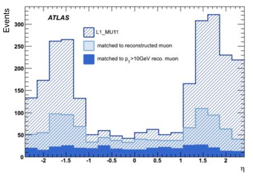
As shown in Fig. 1, 90% of single muon Level-1 triggers originate from reconstructed track segments that cannot be matched offline with muons coming from the interaction point. A large fraction of the spurious Level-1 triggers originates from muon candidates observed in the end-cap regions. The fake muon rate is explained by background radiation incident on the end-cap middle station that is incorrectly identified as muons by the trigger processor. The background radiation consists mostly of neutrons and photons that are generated in the material between the inner and the middle stations where the end-cap toroid magnets are located.
A possible workaround for the excessive trigger rate consists of raising the trigger threshold from 20 GeV, the nominal value, to 40 GeV or in applying trigger prescaling. Both options would successfully reduce the Level-1 trigger rate to an acceptable level, but at the expense of reducing the sensitivity to many physics processes. In particular, a degradation of the muon trigger efficiency at low would be detrimental for Higgs studies because muons are an important signature for many processes involving the Higgs boson.
Apart from issues arising from the excessive Level-1 trigger rate, a performance degradation of muon inner end-cap station detectors is expected due to the high particle fluences. A particle flux reaching up to 15 kHz/cm2 is expected close to the beam pipe during HL-LHC operations. At that level of particle flux, the CSC and MDT chambers will suffer from unacceptable inefficiencies444Inefficiencies are already sizable but reasonable at the nominal LHC luminosity.. The loss of muon precision space points will deteriorate the muon momentum resolution and increase the systematic error of physics studies.
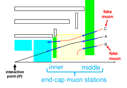
The proposed solution for reducing the trigger rate is to improve the online muon identification in order to recognize and reject fake muons. A schematic diagram of the improved trigger algorithm for muon identification is shown in Fig. LABEL:sub@fig:nsw-algorithm where tracks A, B and C are identified as muons by the middle station. In the new trigger scheme, tracks are identified as muons only if they feature hits in both the inner and middle stations. In addition, the candidate muon track segment reconstructed by the inner station must point to the interaction point and match the middle station measurements. Fake muons (track candidates B and C) typically do not have these features and would be rejected by the algorithm.
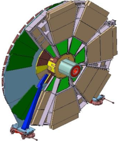
The implementation of this enhanced trigger algorithm necessitates inner station detectors with excellent online track reconstruction abilities with stable performances up to the expected level of particle fluences during HL-LHC operations. The current inner end-cap station detector cannot fullfil these requirements. Therefore, part of the inner end-cap station will be replaced by the New Small Wheels (NSWs), shown in Fig. LABEL:sub@fig:nsw:cut-view and described in the next section.
4 The New Small Wheels
The New Small Wheels (NSWs) are disk-shaped arrangements of 8 large and 8 small pie-slice detector sectors of approximately 10 m in diameter. This geometry was chosen to match the middle station layout. The detector modules, services and shielding of the NSWs must fit in the 1110 mm thick envelope left by the current inner station. The NSW sectors combine the small-strip Thin Gap Chamber (sTGC) [7] and Micromegas555Micro-mesh gaseous structure [8] technologies. Both detector technologies are read out with the VMM ASIC [9] which performs on-detector peak and time measurements of the detector signal.
Individual sectors are assemblies of 2 Micromegas wedges placed between 2 sTGC wedges. Detector wedges are a combination of either 2 Micromegas modules or 3 sTGC modules. Different module types of varying size make up a wedge. The detector modules are quadruplets, meaning they have 4 independent detector layers. This multi-layer configuration was chosen for its robustness and redundancy.
The NSWs are required to have an online angular resolution better than 1 mrad to match the resolution of the middle station required for the run following the Phase-II upgrade. In addition, the muon momentum resolution delivered by the NSWs must be comparable to that of the current inner station aiming for 15% for = TeV muons. Both requirements are satisfied with a spatial resolution better than 100 µm per detector plane. Finally, the NSWs must perform a bunch crossing identification of detector hits which requires, to be achieved, a time jitter better than 25 ns. A number of performance studies, some of which are described in the following, have proven the ability of the chosen NSW detector technologies to satisfy these specifications. Specificities of each detector technology are also described below.
4.1 sTGC technology
Small-strip Thin Gap Chambers (sTGC) are multiwire chambers that operate in the quasi-saturated mode. The design of a sTGC is similar to that of the current muon spectrometer TGC detectors but with an improved spatial resolution and higher particle flux capabilities. The gas volume of a sTGC is contained between two segmented resistive cathodes. In the NSW configuration, each gas volume has one cathode segmented into strips and the other into a pad pattern. Strips are engraved with a pitch of 3.2 mm and are used for the precise measurement of the muon trajectory in the bending plane. Pads are used for the online selection of a specific band of strips to be read out after the passage of a muon thereby reducing the amount of strip data transmitted to the Level-1 trigger processor [10]. The area of pad electrodes varies between approximately 10 and 500 cm2.
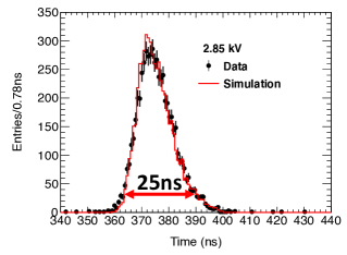
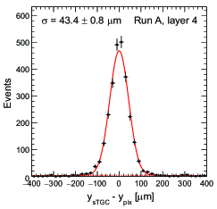
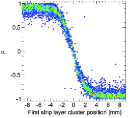
The time jitter of pads was measured in a beam test at CERN in 2012. The measured time distribution, shown in Fig. LABEL:sub@fig:stgc-perf:jitter, demonstrates that more than 80% of the hits are within a time window of 25 ns [5]. The strip spatial resolution and the differential non-linearity bias were measured in a beam test at Fermilab in 2014 [11]. A spatial resolution better than 50 µm was measured with a perpendicular beam and obtained from the distribution of position difference between a reference pixel track and the sTGC measurement shown in Fig. LABEL:sub@fig:stgc-perf:residual. The charge sharing between neighbouring pads was measured in a beam test at CERN 2014 [11]. The measured charge asymmetry, as shown in Fig. LABEL:sub@fig:stgc-perf:asymmetry, demonstrates that charge sharing occurs within a band of 5 mm, which is small compared to the overall dimensions of the pads. Integration studies of the final VMM prototype with sTGC detectors are ongoing at CERN.
4.2 Micromegas technology
Micromegas are micro-pattern gaseous detectors with a thick 5 mm drift gap and a thin 128 µm amplification gap separated by a micro-mesh transparent to electrons. Micromegas operate with a moderate electric field of 600 V/cm in the drift region and a strong electric field of 40 to 50 kV/cm in the amplification region. The ionization electrons created by a muon traversing the drift gap move towards the micro-mesh, and eventually reach the high-field region where electron multiplication takes place. The detector signal is picked up by 300 µm wide copper readout strips located opposite to the micro-mesh and etched on a readout PCB with a pitch of 415 µm. A layer of resistive strips glued over a thin kapton layer is installed above the readout strips aiming to improve the stability of the electric field in the amplification region and reduce the spark probability.
Micromegas quadruplets have two layers equipped with azimuthal strips, called -strips, and two layers equipped with strips arranged in a stereo-strip configuration at an angle of 1.5∘ with respect to the -strips. This strip configuration allows for a precision muon position measurement in the bending plane and a coarse measurement in the coordinate perpendicular to the bending plane.
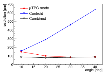
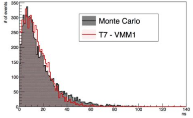
The intrinsic spatial resolution of Micromegas detectors has been measured in several beam test campaigns from 2012 to the present, first using prototypes of small dimensions and then on full-size modules. The spatial resolution as a function of the track incidence angle obtained for small dimension prototypes is shown in Fig. LABEL:sub@fig:mm-perf:spatial-resolution [12]. The spatial resolution obtained when taking the strip charge cluster centroid is better than 90 µm but degrades as a function of the track angle. The resolution obtained using the µTPC mode [12], which uses the timing of strip hits, improves as a function of the angle of incidence. The time distribution of the first strip with a hit, shown in Fig. LABEL:sub@fig:mm-perf:timing was also measured as a way to characterize the online timing performance [5]. Most hits are within a time window of 75 ns.
5 Detector manufacturing
Each NSW combines a total of 96 sTGC and 64 Micromegas quadruplets that are manufactured in member institutes of the ATLAS collaboration. The production of detector components such as the sTGC cathode boards and Micromegas readout boards is carried out in collaboration with industry. The final detector assembly and testing are realized at CERN.
The NSW performs a precise reconstruction of muon track segments which calls for a good control of construction non-conformities during detector manufacturing. In particular, the position of each strip must be known with an accuracy of 40 µm along the precision coordinate and 80 µm along the beam to achieve the target NSW momentum resolution. Stringent tolerances on the geometry of the readout strips are enforced during construction. The alignment between individual strip boards of a quadruplet is achieved using precision pins. Many steps of the assembly process are carried out on a granite table to ensure a good planarity of the detector planes.
This section describes specificities of the sTGC and Micromegas manufacturing. The status of detector production at the time of writing is given.
5.1 sTGC manufacturing
The sTGC production is divided in 5 productions lines, each responsible for manufacturing one or two quadruplet types. In some cases, different steps of the fabrication and quality control process of a production line are shared among different institutes666The sTGC construction sites are PUC (Chile), Shandong (China), TRIUMF, Carleton and McGill (Canada), Technion, TAU and Weizmann (Israel), and PNPI (Russia)..
Series production of sTGC modules is well ongoing in the production lines: several quadruplets have been manufactured and received at CERN. The assembly of the first sTGC wedge will be finished during Fall 2018. The production of cathode boards and other detector components is done in parallel to quadruplet assembly. All sTGC cathode boards will be produced by the end of 2018.
5.2 Micromegas manufacturing
A total of 5 institutes are in charge of Micromegas quadruplet production777The Micromegas construction sites are INFN (Italy), BMBF (Germany), Paris-Saclay (France), JINR (Russia) and Thessaloniki (Greece).. Each institute is responsible for the manufacturing of one quadruplet type. As for the sTGC production, the integration of Micromegas quadruplets to form NSW wedges is done at CERN.
At this stage, 70% of the required readout boards have been manufactured and production will be completed at the beginning of 2019. Series production of drift and readout panels, the main components of Micromegas quadruplets, is ongoing. The assembly of quadruplet is started in all construction sites. First quadruplets have been received at CERN and wedge integration is on the way to start.
6 Summary
The LHC instantaneous luminosity will increase by up to 5 to 7 times the design value following a series of upgrades planned over the next decade. In order to benefit from the physics opportunities offered by an upgraded LHC, the New Small Wheels (NSWs) will replace part of the muon end-cap station of ATLAS as a mean to improve the online muon identification capability.
The NSWs will perform the precise reconstruction of candidate muon track segments and will combine the sTGC and Micromegas detector technologies. Detector construction for the NSWs is a worldwide effort shared among multiple physics institutes. Module manufacturing is well ongoing and wedge assembly has started.
References
- [1] L. Evans and P. Bryant (editors), LHC machine, JINST 3 (2008) S08001.
- [2] G. Apollinari et al., High-Luminosity Large Hadron Collider (HL-LHC): Technical Design Report V. 0.1, CERN-2017-007-M, CERN, Geneva, 2017, URL: https://cds.cern.ch/record/2284929.
- [3] ATLAS Collaboration, The ATLAS Experiment at the CERN Large Hadron Collider, JINST 3 (2008) S08003.
- [4] P. Vankov on behalf of the ATLAS Collaboration, ATLAS Future Upgrade, PoS 273 (2016) 061 proceedings of BEAUTY2016, ATL-UPGRADE-PROC-2016-003.
- [5] ATLAS Collaboration, New Small Wheel Technical Design Report, CERN-LHCC-2013-006, CERN, Geneva, Jun, 2013, URL: https://cds.cern.ch/record/1552862.
- [6] ATLAS Collaboration, Performance of the ATLAS muon trigger in pp collisions at TeV, Eur. Phys. J. C 75 (2015) 120.
- [7] S. Majewski et al., A thin multiwire chamber operating in the high multiplication mode, Nucl. Instrum. Methods Phys. Res. 217 (1983) 265.
- [8] Y. Giomataris et al., Micromegas: a high-granularity position-sensitive gaseous detector for high particle-flux environments, Nucl. Instrum. Meth. A 376 (1996) 29.
- [9] G. Iakovidis on behalf of the ATLAS Muon Collaboration, VMM - An ASIC for Micropattern Detectors, EPJ Web Conf. 174 (2018) 07001 ATL-MUON-PROC-2015-015.
- [10] L. Guan on behalf of the ATLAS Muon Collaboration, Trigger algorithms and electronics for the ATLAS muon new small wheel upgrade, JINST 11 (2016) C01083.
- [11] A. Abusleme et al., Performance of a full-size small-strip thin gap chamber prototype for the ATLAS new small wheel muon upgrade, Nucl. Instrum. Meth. A 817 (2016) 85.
- [12] M. Iodice on behalf of the Muon ATLAS MicroMegas Activity (MAMMA) Collaboration, Performance studies of MicroMegas for the ATLAS experiment, JINST 9 (2014) C01017.