Determination of spin Hall angle in heavy metal/CoFeB-based heterostructures with interfacial spin-orbit fields
Abstract
Magnetization dynamics in W/CoFeB, CoFeB/Pt and W/CoFeB/Pt multilayers was investigated using spin-orbit-torque ferromagnetic resonance (SOT-FMR) technique. An analytical model based on magnetization dynamics due to SOT was used to fit heavy metal (HM) thickness dependence of symmetric and antisymmetric components of the SOT-FMR signal. The analysis resulted in a determination of the properties of HM layers, such as spin Hall angle and spin diffusion length. The spin Hall angle of -0.36 and 0.09 has been found in the W/CoFeB and CoFeB/Pt bilayers, respectively, which add up in the case of W/CoFeB/Pt trilayer. More importantly, we have determined effective interfacial spin-orbit fields at both W/CoFeB and CoFeB/Pt interfaces, which are shown to cancel Oersted field for particular thicknesses of the heavy metal layers, leading to pure spin-current-induced dynamics and indicating the possibility for a more efficient magnetization switching.
I Introduction
In heavy metal (HM) layers exhibiting significant spin-orbit coupling, the charge current () may be converted into the spin current () due to the spin Hall effect (SHE). The generated spin current, in turn, may exert a torque on the magnetization in an adjacent ferromagnet (FM) hirsch_spin_1999 ; sinova_universal_2004 . This phenomenon can be used, for instance, to control the magnetization state of next generation MRAM cells liu_spin-torque_2012 ; miron_perpendicular_2011 or to drive the magnetization precession in spin torque oscillators liu_magnetic_2012 ; demidov_magnetic_2012 . It has been already established, that in HM/FM bilayers the magnetization dynamics is driven by two components (damping-like and field-like) of the spin-orbit-torque (SOT) kim_anomalous_2014 and by the Oersted field produced by the charge current. This effect is often used to quantitatively analyze the spin Hall angle = / liu_spin-torque_2011 . However, one can also expect the interface charge-spin conversion originating from the Rashba-type spin-orbit interactions miron_perpendicular_2011 ; kim_layer_2013 ; cecot_influence_2017 to play a significant role in such systems. A strong interface effect has already been found in Ta/CoFeB bilayers allen_experimental_2015 ; cecot_influence_2017 and recently in Ta/CoFeB/Pt trilayers huang_engineering_2018 by analyzing the HM and FM thickness dependence of the SOT-FMR signal lineshape.
The above mentioned Rashba phenomenon at the interface (known also as the Edelstein-Rashba effect) has been modeled, among others, for a magnetized two-dimensional electron gas (2DEG) in both ballistic and diffusive regimes Manchon2009 ; Ado ; Dyrdal2017 ; Kim2017 ; Borge ; Xiao . Theoretical results show that the SOT due to interfacial non-equilibrium (current-induced) spin polarization has symmetry similar to that induced by the spin Hall effect in heavy metals, i.e., there can be both damping-like and field-like components. However, in contrast to the spin Hall-induced torque and earlier mechanisms of spin-transfer torque (STT), the interfacial spin-orbit coupling (ISOC) acts as an effective field on the magnetization and, therefore, is not associated with transfer of the transverse part of spin current. Moreover, the field-like component is mostly dominating, which can be attributed to a weak short-range spin-independent disorder Borge .
Another related interfacial effect that occurs at ferromagnet/heavy metal interfaces is the so-called spin Hall magnetoresistance effect (SMR) althammer_quantitative_2013 ; avci_magnetoresistance_2015 ; Chen2016 ; Kim2016 ; Choi ; manchon_new_2015 . In the bilayer under discussion, some of the electrons flowing from the HM into ferromagnet can have spin component parallel to the magnetization of the ferromagnetic layer – due to external magnetic field, magnetic proximity effect, or magnetic anisotropy in the ferromagnet. This component of spin current is reflected from the interface and via the inverse spin Hall effect (ISHE) in HM miao_inverse_2013 is converted to the charge current flowing parallel to the initial current, which results in a reduced resistance. In contrast, the perpendicular component of spin current, that gives rise to spin torque exerted on the magnetization, is almost completely absorbed, and thus does not lead to charge current induced by ISHE. Although this effect occurs mostly near to the interface, it is strongly dependent on the thickness of HM layer. It has been previously assumed that the origin of FMR signal in the case of HM/FM systems is the anisotropic magnetoresistance (AMR) of FM liu_spin-torque_2012 ; allen_experimental_2015 ; taniguchi_spin-transfer_2015 , which might be the case for some systems. However, one should also take into account a contribution to the signal from SMR, as it has the same angular symmetry as AMR Harder2016 ; Kim2016 ; Choi ; cho_large_2015 .
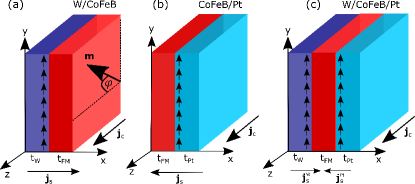
In this work, the SOT-FMR technique is used to investigate W/CoFeB and CoFeB/Pt bilayers, shown schematically in Fig. 1(a) and (b), as a function of thickness of HM (). We have chosen W pai_spin_2012 ; skowronski_temperature_2017 and Pt hahn_comparative_2013 ; skinner_spin-orbit_2014 ; yang_layer_2015 ; sagasta_tuning_2016 as a source of spin current, since they are characterized by the spin Hall angles of opposite signs yu_large_2016 ; woo_enhanced_2014 ; bekele_dominancy_2018 . The evolution of symmetric and antisymmetric parts of the resonance signal with is fitted using the developed analytical model. As a result, the magnitudes of the effective magnetic fields associated with damping-like and field-like components of SOT, as well as interface effects, such as SMR and ISOC, are determined. The model also enables evaluation of the spin Hall angle and spin diffusion length for each bilayer system. Finally, in the case of W/CoFeB/Pt trilayer, shown schematically in Fig. 1(c), we have used the values obtained from the constituent bilayers in order to identify the contributions from both heavy metals and their interfaces to the SOT induced in the trilayer system.
The paper is organized as follows: Section II includes description of the experiment. Theoretical model, in turn, is presented in Sec. III, where the formulas for mixing voltage and spin Hall angle are derived and discussed. Experimental results are presented in Sec. IV, together with theoretical predictions based on the previous section. Finally, summary and concluding remarks are presented in Sec. V.
II Experiment
Magnetron sputtering technique was used to deposit the following multilayer structures on Si/SiO2 substrates: W()/CoFeB(5)/Ta(1), CoFeB(5)/Pt() and W(5)/CoFeB(5)/Pt() (thicknesses in nm). The CoFeB layers were deposited from an alloy target with the composition of 20 at % Co, 60 at % Fe, and 20 at % B. In case of W sputtering, a low DC power of 4 W and 6 cm target-sample distance was used, which resulted in deposition rate of 0.01 nm/s. Such conditions are essential for growth of thick W layers in highly resistive -phase hao_beta_2015 ; hao_giant_2015 ; neumann_temperature_2016 . The remaining materials were deposited with a 15 W DC power. For multilayers with a top material susceptible to oxidation, 1-nm thick Ta layer was deposited, which oxidized completely and formed a non-conducting protection layer. The thickness of wedges ranged from 0 to 10 nm in case of and .
The bi- and trilayers were subsequently patterned into 100-m long () and 20-m wide () strips using electron-beam lithography and lift-off process with Al(10)/Au(50) contact pads. The resistivity of HM and FM was determined using the method described in Ref. [kawaguchi_anomalous_2018, ] and the resistivity of FM, whose thickness was constant, was on average . The angular dependence of the resistance, enabling AMR and SMR determination, was measured at fixed magnetic field (which is sufficient to saturate the magnetization) applied at varying angle with respect to the microstrip axis, using a custom-build rotating probe station. During the SOT-FMR measurements, an amplitude modulated radio-frequency (RF) current of the corresponding power of = 16 dBm and the frequency changing between 4 and 10 GHz was injected into the microstripe. The mixing voltage () was measured using lock-in amplifier synchronized to the RF signal. An in-plane magnetic field () applied at = 30∘ with respect to the microstrip axis was swept from 0 up to 1250 Oe.
III Origin of the signal
Mixing voltage generated in SOT-FMR experiment can be written down as time-averaged product of RF current with amplitude , , and time-dependent resistance, , of the system,
| (1) |
We assume that resistance changes due to a combination of the AMR and SMR effects Harder2016 ,
| (2) |
where is the time-dependent tilt-angle of the magnetization from its equilibrium orientation, , and is the time-independent component of the resistance, which contains terms from both AMR and SMR. Here is the increment of anisotropic magnetoresistance of CoFeB assumed to be weakly dependent on the heavy metal thickness. In turn, the SMR contribution Chen2016 ; Kim2017 ,
| (3) |
is strongly dependent on the thickness of HM layer. Furthermore, in Eq. (3) is the spin Hall angle of the HM, is the spin diffusion length in this material, and is the dimensionless real part of the spin-mixing conductance. In Eq. (3) we omitted the imaginary part of the spin-mixing conductance, as vanishingly small. The real part of spin-mixing conductance can be deduced from experiment according to the formula Tserkovnyak
| (4) |
where is the difference between Gilbert damping coefficients of pure CoFeB and CoFeB with W or Pt layers attached, denotes saturation magnetization of the HM/FM bilayer, and is the gyromagnetic ratio. The relevant parameters have been collected in Table 1. As is derived experimentally, we treat it as an effective spin-mixing conductance, which also takes into account possible effects due to spin memory losses Qui_enhanced_2016 .
The mixing voltage can be written down as follows:
| (5) |
where is the equilibrium angle of magnetization (determined by applied magnetic field ) with respect to the direction of current, and is the component of magnetization vector found by solving Landau-Lifshitz-Gilbert (LLG) equation in the macrospin approximation,
| (6) |
Here, is a unit vector along the magnetization, and
| (7) |
determines the torques exerted on the magnetization due to effective magnetic field consisting of the demagnetization field, anisotropy field, and external magnetic field, and due to the current-induced field .
The current-induced field consists of in-plane, , and out-of-plane, , terms. In systems consisting of FM and HM layers, the only contribution to comes from damping-like field, , due to spin currents induced by the spin Hall effect in heavy metal layers. The in-plane field, on the other hand, contains components due to Oersted field, , and interfacial spin-orbit field, .
The damping-like contributions to the effective field from W and Pt have the same sign due to opposite signs of the corresponding spin Hall angles,
| (8) |
where corresponds to the spin current flowing from W (Pt) layer. The amplitude of damping-like field can be written in the following form:
| (9) |
where
| (10) |
is the so-called damping-like spin Hall efficiency.
We also introduce the Oersted field,
| (11) |
and the spin-orbit field,
| (12) |
with being the amplitude of the effective spin-orbit field. In the following considerations we include the effective field corresponding to the field-like torque induced by the spin Hall effect into the spin-orbit field. Thus, the amplitude contains both the interfacial Rashba-Edelstein and spin Hall field-like contributions.
By linearizing the LLG equation (6) and inserting the obtained expression for into Eq. (5), one obtains the following formula for the mixing voltage,
| (13) |
where is the amplitude of the symmetric part of the signal,
| (14) |
and is the amplitude of the antisymmetric component of mixing voltage,
| (15) |
To obtain the effective spin Hall angle of the structure one could use the ratio of symmetric and antisymmetric contributions to the mixing voltage, which yields
| (16) |
This formula, however, does not give the proper effective spin Hall angle (defined as ), as it takes into account all the out-of-plane contributions. This formula can be rewritten as
| (17) |
or equivalently
| (18) |
Only assuming that , which is fulfilled for thick HM layers, one obtains the proper effective spin Hall angle, consistent with previous works (e.g. Ref. [liu_spin-torque_2012, ]),
| (19) |
IV Results and discussion
| W/CoFeB | CoFeB/Pt | Units | |
| 116 | 112 | ||
| 3.4 | 8.0 | ||
| 4.0 | 4.0 | ||
| 0.6 | 4.0 | ||
| 8 | 7.5 | Tnm | |
| 0.6 | 3.9 | ||
| 2 | 2.9 | ||
| -0.36 | 0.09 | ||
| 1.3 | 2.2 | nm | |
| -0.27 | 0.54 | Oe |
The resistivity of each material was determined from the measured sheet conductance of each microstripe as a function of , according to the procedure described in Ref. [kawaguchi_anomalous_2018, ]. The resistivity of W was constant for the thicknesses above 2 nm: = 116 cm, which indicates the existence of the highly-resistive -phase. In CoFeB/Pt bilayer the resistivity = 112 cm was determined. However, we found that the resisistivity of magnetron sputtering deposited Pt depends on whether Pt is deposited on crystalline underlayer (Co) or amorphous CoFeB alloy. In the first case, depending on the thickness of the bottom layer, the resistance was from about 20 to 100 sagasta_tuning_2016 ; kawaguchi_anomalous_2018 ; schoen_ultra-low_2016 , while in the second case from 100 to 200 Conca2017 .
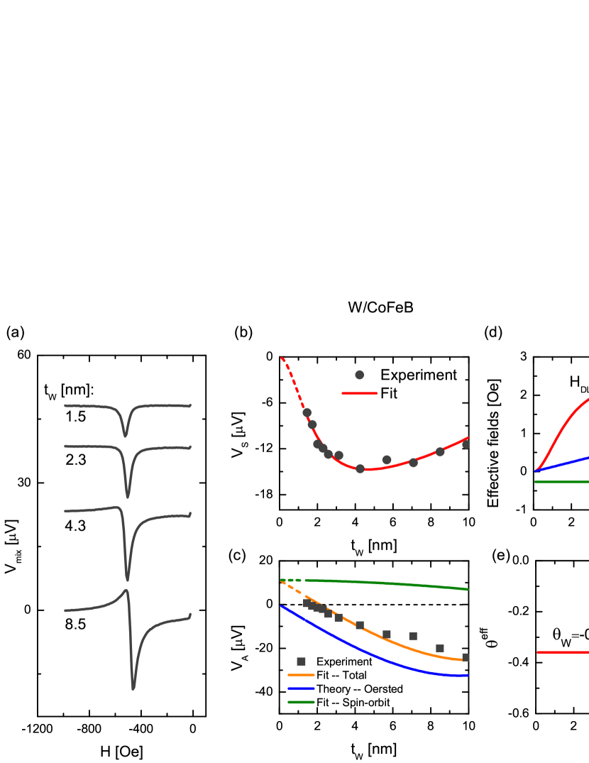
Now, we focus on the magnetization dynamics investigated by the SOT-FMR technique. Mixing voltage, , as a function of magnetic field, , measured in W/CoFeB microstripes for selected thicknesses, , is presented in Fig. 2(a). For each , the signal is decomposed into symmetric () and antisymmetric () Lorentz functions liu_spin-torque_2011 . The dependence of the amplitudes and on is shown in Fig. 2(b) and (c), together with the corresponding fitting based on the theoretical model presented in the previous section. Such an approach enables quantitative separation of the contributions from the Oersted field and interfacial spin-orbit torque to the antisymmetric part of the signal. In addition, it was found that in the case of W/CoFeB bilayer with 5-nm thick FM, the measured magnetoresistance is weakly dependent on the thickness of W, indicating AMR-like effect and negligible SMR (in contrast to thin FM case, where SMR is dominating cho_large_2015 ). As a consequence, the resulting SOT-FMR signal is not described well with the magnetoresistance change modelled with Eq. (3). Thus, the experimental results were taken instead and the model was interpolated for small thicknesses of W layer. Based on Eqs. (9), (11), and (12), the evolution of the effective fields as a function of has been determined and is presented in Fig. 2(d). In the case of W, the interface spin-orbit field is relatively weak: = -0.27 Oe. The experimentally determined values of , based on Eq. (19), approach the fitted value of = -0.36 for thick W layers.
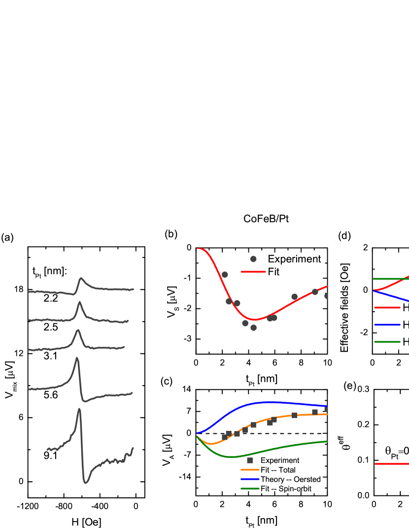
Similar experimental procedure as well as quantitative analysis were repeated for the CoFeB(5)/Pt() stripes. The corresponding results are presented in Fig. 3. Unlike the W case, the DC mixing voltage of Pt stripes unequivocally changes sign with increasing , as shown in Fig. 3(a). Thickness dependence of the corresponding symmetric and antisymmetric components are shown in Fig. 3(b) and (c), respectively. Behavior of the symmetric component is well explained by a combination of the spin Hall induced damping-like field and SMR effect, in contrast to the above described W/CoFeB bilayer. Fitting of the model to the experimental data allowed to obtain the spin Hall angle , opposite in sign to the spin Hall angle obtained for W/CoFeB, and the spin diffusion length . Both values agree with the data presented in the relevant literature Rojas_Sanchez_spin_2014 ; zhang_role_2015 ; sagasta_tuning_2016 .
The sign change of the antisymmetric part of the signal occurs due to a stronger, compared to W/CoFeB bilayer, interfacial spin-orbit field, = 0.54 Oe, which dominates for . Similar field-like torque contribution in Pt/Co/MgO multilayers was measured for the same Pt thickness using harmonic Hall voltage measurements nguyen_spin_2016 .
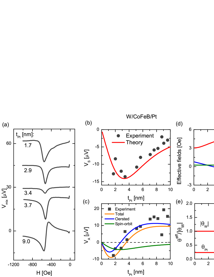
Finally, the spin-orbit-torque-induced dynamics in W/CoFeB/Pt trilayers was investigated and the corresponding results are shown in Fig. 4. Similar to the CoFeB/Pt bilayer, symmetry of the SOT-FMR signal changes for , as shown in Fig. 4(c). However, in the case of a trilayer, the spin currents from both HM layers are absorbed in FM, which results in an increase in . Note, that for = 2.5 nm, the Oersted field and interfacial spin-orbit contributions from both W and Pt are minimized and therefore a pure spin current induced dynamics is observed. Solid lines in Fig. 4(b) and (c) are drawn based on the fitting parameters obtained for W/CoFeB and CoFeB/Pt bilayers showing good agreement between the experimental values and theoretical predictions.
The effective spin Hall angle of the trilayer system, shown in Fig. 4(e), is 1.5 times larger than that for W/CoFeB bilayer alone for , while for thicker platinum it decreases to a value closer to the one obtained for the CoFeB/Pt bilayer. This drop can be explained by larger spin-mixing conductance at the CoFeB/Pt interface and thus larger spin current flowing through this interface.
V Summary
In summary, the spin-orbit-torque-induced dynamics in W/CoFeB and CoFeB/Pt bilayers and W/CoFeB/Pt trilayer was investigated experimentally by the spin-orbit-torque ferromagnetic resonance technique. Both symmetric and antisymmetric parts were resolved in the SOT-FMR signals from the microstripes investigated. Variation of the magnitudes of the corresponding signals with increasing heavy metal thickness was fitted to the developed theoretical model. From the application point of view, it is important to note that when combining ferromagnets with materials, which exhibit strong spin-orbit coupling, such as W and Pt, interfaces between those materials play very important role in determination of the torques exerted on magnetization and other properties of the constituent materials. We have determined the magnitude of interfacial spin-orbit fields from W/CoFeB and CoFeB/Pt interfaces and shown how they influence the spin Hall angle and spin diffusion length in these bilayers as well as in W/CoFeB/Pt trilayer. In particular, we have shown that for specific thicknesses of the Pt and W layers, the Oersted field is cancelled by the interfacial spin-orbit field, which leads to a pure spin-current induced dynamics.
Acknowledgments
The authors would like to thank J. Chęciński for help in calculations and M. Schmidt and J. Aleksiejew for technical support. This work was supported by the National Science Centre, Poland, grant No. UMO-2015/17/D/ST3/00500. Ł. K., S. Ł., K. G., and T. S. acknowledge support from National Science Centre research project 2016/23/B/ST3/01430 (SPINORBITRONICS). Microfabrication was performed at Academic Center for Materials and Nanotechnology of AGH University.
References
- (1) J. E. Hirsch, Phys. Rev. Lett. 83, 1834–1837 (1999).
- (2) J. Sinova, D. Culcer, Q. Niu, N. A. Sinitsyn, T. Jungwirth, and A. H. MacDonald, Phys. Rev. Lett. 92, 126603 (2004).
- (3) L. Liu, C.-F. Pai, Y. Li, H. W. Tseng, D. C. Ralph, and R. A. Buhrman, Science 336, 555 (2012).
- (4) I. M. Miron, K. Garello, G. Gaudin, P.-J. Zermatten, M. V. Costache, S. Auffret, S. Bandiera, B. Rodmacq, A. Schuhl, and P. Gambardella, Nature 476, 189–193 (2011).
- (5) L. Liu, C.-F. Pai, D. Ralph, and R. Buhrman, Phys. Rev. Lett. 109, 186602 (2012).
- (6) V. E. Demidov, S. Urazhdin, H. Ulrichs, V. Tiberkevich, A. Slavin, D. Baither, G. Schmitz, and S. O. Demokritov, Nat. Mater. 11, 1028–1031 (2012).
- (7) J. Kim, J. Sinha, S. Mitani, M. Hayashi, S. Takahashi, S. Maekawa, M. Yamanouchi, and H. Ohno, Phys. Rev. B 89, 174424 (2014).
- (8) L. Liu, T. Moriyama, D. C. Ralph, and R. A. Buhrman, Phys. Rev. Lett. 106, 036601 (2011).
- (9) J. Kim, J. Sinha, M. Hayashi, M. Yamanouchi, S. Fukami, T. Suzuki, S. Mitani, and H. Ohno, Nat. Mater. 12, 240–245 (2013).
- (10) M. Cecot, Ł. Karwacki, W. Skowroński, J. Kanak, J. Wrona, A. Żywczak, L. Yao, S. van Dijken, J. Barnaś, and T. Stobiecki, Sci. Rep. 7 (2017).
- (11) G. Allen, S. Manipatruni, D. E. Nikonov, M. Doczy, and I. A. Young, Phys. Rev. B 91, 144412 (2015).
- (12) L. Huang, S. He, Q. J. Yap, and S. T. Lim, Applied Physics Letters 113, 022402 (2018).
- (13) A. Manchon and S. Zhang, Phys. Rev. B 79, 094422 (2009).
- (14) I. A. Ado, O. A. Tretiakov, and M. Titov, Phys. Rev. B 95, 094401 (2017).
- (15) A. Dyrdał, J. Barnaś, and V. K. Dugaev, Phys. Rev. B 95, 245302 (2017).
- (16) K.-W. Kim, K.-J. Lee, J. Sinova, H.-W. Lee, and M. D. Stiles, Phys. Rev. B 96, 104438 (2017).
- (17) J. Borge and I. V. Tokatly, Phys. Rev. B 96, 115445 (2017).
- (18) C. Xiao and Q. Niu, Phys. Rev. B 96, 035423 (2017).
- (19) M. Althammer, S. Meyer, H. Nakayama, M. Schreier, S. Altmannshofer, M. Weiler, H. Huebl, S. Geprägs, M. Opel, R. Gross, D. Meier, C. Klewe, T. Kuschel, J.-M. Schmalhorst, G. Reiss, L. Shen, A. Gupta, Y.-T. Chen, G. E. W. Bauer, E. Saitoh, and S. T. B. Goennenwein, Phys. Rev. B 87, 224401 (2013).
- (20) C. O. Avci, K. Garello, J. Mendil, A. Ghosh, N. Blasakis, M. Gabureac, M. Trassin, M. Fiebig, and P. Gambardella, Applied Physics Letters 107, 192405 (2015).
- (21) Y.-T. Chen, S. Takahashi, H. Nakayama, M. Althammer, S. T. B. Goennenwein, E. Saitoh, and G. E. W. Bauer, J. Phys.: Condens. Matter 28, 103004 (2016).
- (22) J. Kim, P. Sheng, S. Takahashi, S. Mitani, and M. Hayashi, Phys. Rev. Lett. 116, 097201 (2016).
- (23) J.-G. Choi, J. W. Lee, and B.-G. Park, Phys. Rev. B 96, 174412 (2017).
- (24) A. Manchon, H. C. Koo, J. Nitta, S. M. Frolov, and R. A. Duine, Nat. Mater. 14, 871 (2015).
- (25) B. F. Miao, S. Y. Huang, D. Qu, and C. L. Chien, Phys. Rev. Lett. 111, 066602 (2013).
- (26) T. Taniguchi, J. Grollier, and M. D. Stiles, Phys. Rev. Applied 3, 044001 (2015).
- (27) M. Harder, Y. Gui, and C.-M. Hu, Phys. Rep. 661, 1 (2016).
- (28) S. Cho, S.-h. C. Baek, K.-D. Lee, Y. Jo, and B.-G. Park, Sci. Rep. 5, 14668 (2015).
- (29) C.-F. Pai, L. Liu, Y. Li, H. W. Tseng, D. C. Ralph, and R. A. Buhrman, Applied Physics Letters 101, 122404 (2012).
- (30) W. Skowroński, M. Cecot, J. Kanak, S. Ziętek, T. Stobiecki, L. Yao, S. van Dijken, T. Nozaki, K. Yakushiji, and S. Yuasa, Applied Physics Letters 109, 062407 (2016).
- (31) C. Hahn, G. de Loubens, O. Klein, M. Viret, V. V. Naletov, and J. Ben Youssef, Phys. Rev. B 87, 174417 (2013).
- (32) T. D. Skinner, M. Wang, A. T. Hindmarch, A. W. Rushforth, A. C. Irvine, D. Heiss, H. Kurebayashi, and A. J. Ferguson, Applied Physics Letters 104, 062401 (2014).
- (33) T. Yang, M. Kong, M. Kohda, T. Seki, K. Takanashi, and J. Nitta, Japanese J. Appl. Phys. 54, 04DM05 (2015).
- (34) E. Sagasta, Y. Omori, M. Isasa, M. Gradhand, L. E. Hueso, Y. Niimi, Y. Otani, and F. Casanova, Phys. Rev. B 94, 060412 (2016).
- (35) J. Yu, X. Qiu, W. Legrand, and H. Yang, Applied Physics Letters 109, 042403 (2016).
- (36) S. Woo, M. Mann, A. J. Tan, L. Caretta, and G. S. D. Beach, Applied Physics Letters 105, 212404 (2014).
- (37) Z. A. Bekele, K. Meng, J. Miao, X. Xu, and Y. Jiang, Solid State Communications 274, 41 – 45 (2018).
- (38) Q. Hao, W. Chen, and G. Xiao, Applied Physics Letters 106, 182403 (2015).
- (39) Q. Hao and G. Xiao, Phys. Rev. Appl. 3, 034009 (2015).
- (40) L. Neumann, D. Meier, J. Schmalhorst, K. Rott, G. Reiss, and M. Meinert, Applied Physics Letters 109, 142405 (2016).
- (41) M. Kawaguchi, D. Towa, Y.-C. Lau, S. Takahashi, and M. Hayashi, Applied Physics Letters 112, 202405 (2018).
- (42) Y. Tserkovnyak, A. Brataas, G. E. W. Bauer, and B. I. Halperin, Rev. Mod. Phys. 77, 1375 (2005).
- (43) X. Qiu, W. Legrand, P. He, Y. Wu, J. Yu, R. Ramaswamy, A. Manchon, and H. Yang, Phys. Rev. Lett. 117, 217206 (2016).
- (44) M. A. W. Schoen, D. Thonig, M. L. Schneider, T. J. Silva, H. T. Nembach, O. Eriksson, O. Karis, and J. M. Shaw, Nat. Phys. 12, 839–842 (2016).
- (45) A. Conca, B. Heinz, M. R. Schweizer, S. Keller, E. T. Papaioannou, and B. Hillebrands, Phys. Rev. B 95, 174426 (2017).
- (46) J.-C. Rojas-Sánchez, N. Reyren, P. Laczkowski, W. Savero, J.-P. Attané, C. Deranlot, M. Jamet, J.-M. George, L. Vila, and H. Jaffrès, Phys. Rev. Lett. 112, 106602 (2014).
- (47) W. Zhang, W. Han, X. Jiang, S.-H. Yang, and S. S. P. Parkin, Nat. Phys. 11, 496–502 (2015).
- (48) M.-H. Nguyen, D. C. Ralph, and R. A. Buhrman, Phys. Rev. Lett. 116, 126601 (2016).