IAC-18-A7.2.5.47547
Exploring the Kuiper Belt with Sun-diving Solar Sails
Elena Anconaa, Roman Ya. Kezerashvilib,c, and Gregory L. Matloffb
aIndependent researcher, elena.ancona@gmail.com
bNew York City College of Technology, The City University of New York, Brooklyn, NY, USA, rkezerashvili@citytech.cuny.edu, gmatloff@citytech.cuny.edu
cThe Graduate School and University Center, The City University of New York, NY, USA
Abstract
We discuss a possiblity to survey many Kuiper Belt Objects (KBO) with a single launch using a few small-scale spacecraft, each equipped with solar sails, which could be unfurled from a single interplanetary bus at the perihelion of that craft’s solar orbit. Each small-scale spacecraft would carry a scientific payload and would be directed to intersect one or more KBOs. The proposed scenario is the following: the sails are carried as a payload to a relatively small heliocentric distance (0.1 - 0.3 AU); once at the perihelion, the sails are deployed. Besides electromagnetic propulsion due to the solar radiation, another mechanism could be convenient: thermal desorption, a physical process of mass loss which can provide additional thrust as heating liberates atoms, embedded on the surface of a solar sail. Therefore, the sails experience additional propulsive force due to the thermal desorption that dramatically increases the distance that sails travel per year.
Keywords: Solar Sail, Deep Space Exploration, Thermal Desorption.
Introduction
The Kuiper Belt is a disc-shaped region extending 35-50 AU from the Sun that is populated by volatile-rich objects including the dwarf planet Pluto and more than 100,000 bodies larger than 100 kilometers across and as many as a trillion smaller comets. After the discovery of Pluto in 1930, the next discovery of a Kuiper Belt Object (KBO) was in 1992. The NASA New Horizons Probe encountered Pluto and its satellites in 2015 and is in route to a second Kuiper Belt destination [1]. It is possible to survey many Kuiper Belt Objects (KBOs) using a single launch. Many small-scale spacecraft, each equipped with solar sails, could be unfurled from a single interplanetary bus at the perihelion of that craft’s solar orbit. Each small-scale spacecraft would carry a scientific payload and would be directed to intersect one or more KBOs. The following question arises: Why should we use solar sail?
The exhaust speed determines the upper limit for a spacecraft’s velocity. Conventional space transportation systems typically employ chemical or solar electric propulsion. Chemical propulsion systems have effectively reached the limit of their maximum performance potential, with further development activities focused mainly on improving reliability and reducing cost. Moreover, the chemical rockets are severely limited for such missions because chemical reactions have a very low energy yield per unit of fuel mass, and therefore have rather low burn temperatures, less than 1 eV. Consequently, even though chemical reactions can produce very large thrusts because of large mass-flow rates for short durations, their exhaust speeds are necessarily very low. Solar electric propulsion (SEP) is increasingly being utilized for station keeping, orbit transfer, and deep space propulsion. Whereas there is still substantial room for improvement in power, performance, and reliability, SEP systems are not sufficiently transformative to enable rapid interplanetary transit, let alone missions into interstellar space. We would normally expect that the propulsion methods based on fission, fusion, and antimatter-matter annihilation can provide high-temperature exhausts because their mass-energy conversion efficiencies are relatively high: 0.0009, 0.0038, and 1. However, nuclear electric propulsion [2] and nuclear thermal propulsion have the main disadvantage of the large mass of the reactor which necessitates many heavy lift launches to assemble the transfer vehicle. For space flight, the main advantage of fusion propulsion would be the very high specific impulse, and a fusion rocket may produce less radiation than a fission rocket, reducing the mass needed for shielding. A great deal of work is required before fusion-propelled space flight can be achieved. The recent review of fusion concepts for propulsion can be found in Ref. [3].
Because interstellar distances are very great, a tremendous velocity is needed to get a spacecraft to its destination in a reasonable amount of time. Acquiring such a velocity on launch and getting rid of it on arrival will be a formidable challenge. The solar sail provides very low but inexhaustible thrust along the direction of motion of a spacecraft bound for the outer solar system, which increases the distance from the Sun. In this paper we propose to use a solar sail coated by the material that undergoes the thermal desorption at a particular temperature [4]. Once at the perihelion of the heliocentric orbit that is determined by the temperature of desorption of the coating, the solar sail is deployed, the thermal desorption process can provide an additional significant thrust for the sail [5]. The sail will be accelerated to the high velocity due to the thermal desorption of the coating material. After the desorption coating sublimes away, the sail performs as a conventional solar sail.
The paper is organized in the following way: in Sec. 2 we describe the sail craft configuration. The orbital mechanics of a considered scenario is discussed in Sec. 3. Results of calculations and discussion are given in Sec. 4, followed by conclusions in Sec. 5.
Sail Spacecraft Configuration
A solar sail is large sheet of low areal density material whose only source of energy is the Sun electromagnetic flux. The concept of solar sailing has been successfully tested by the Japanese IKAROS solar sail spacecraft [6, 7] launched by JAXA and shortly after that by Nanosail-D2 launched by NASA [8]. Following these experiences let us consider a square-shaped sail with area . One important characteristic of a solar sail is the areal mass density , which is the ratio mass of the sail to the reflective area : . The total mass of solar sail spacecraft is composed of the mass of payload and mass of the sail: . To use the advantage of the acceleration due to the thermal desorption the reflective area of the sail should be coated by the material that undergoes the thermal desorption at the particular temperature [4]. We are considering a solar sail coated by material that undergoes desorption at a particular temperature as a result of heating by the solar radiation at a particular heliocentric distance [5]. Over the substrate there is a layer of a highly reflective material, e. g. beryllium, aluminum, that is coated by the substance that undergoes the thermal desorption at temperature . Let us consider the total mass of the coating required for the desorption. This mass covers the surface area of a solar sail. We assume that is comparable with the mass of the solar sail , while is the coating mass at any instant . We assume that the desorption rate of the coating material is constant. Below we present the analysis for a single solar sail and then consider using a single launch deployment of a few small-scale spacecraft, each equipped with solar sails that could be unfurled from a single interplanetary bus at the perihelion of that craft’s solar orbit.
Proposed Scenario
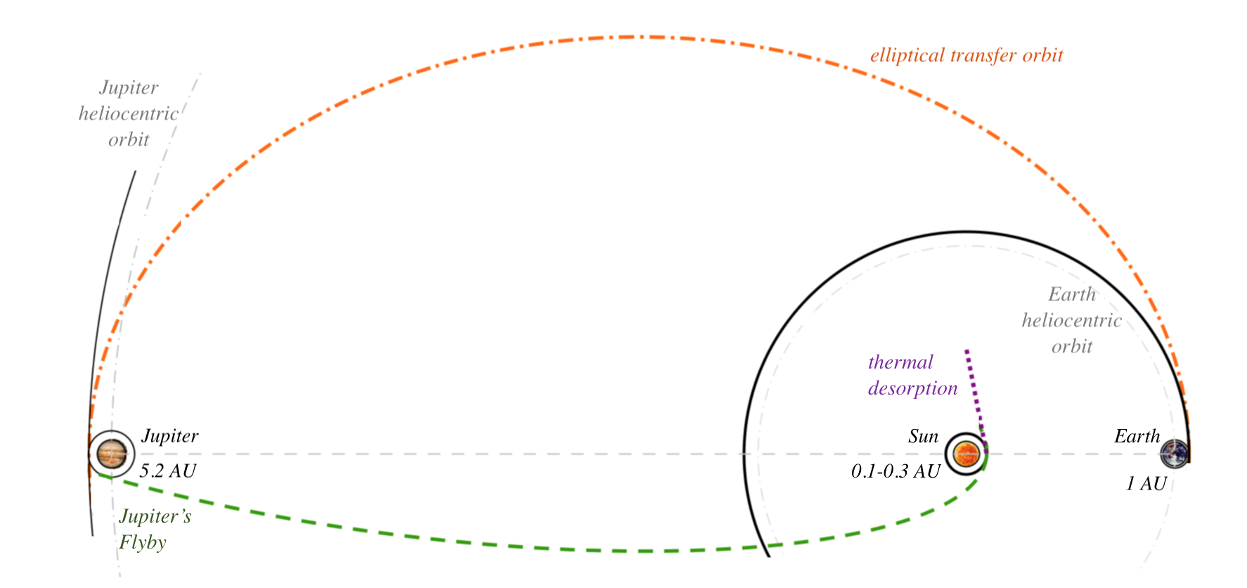
Let us focus on the orbital dynamics of a solar sail coated with materials that undergo thermal desorption at a specific temperature, as a result of heating by solar radiation at the perihelion of a particular heliocentric orbit. We are considering the following scenario. Using the conventional spacecraft that carries the solar sails, the transfer occurs from Earth’s orbit to Jupiter’s orbit. After that a Jupiter fly-by leads to the heliocentric orbit with the perihelion close to the Sun, where the temperature corresponds the temperature of thermal desorption of the coating material [9]. At this point the sail is deployed and thermal desorption becomes active. During a short period, the sail is accelerated by the thermal desorption and as solar radiation pressure. To simplify, during the process of the thermal desorption one can neglect the acceleration due to solar radiation because this acceleration is an order of magnitude less than acceleration due to thermal desorption. It is very important to remember that in order to have an effective desorption, high temperatures are required. So one should consider a scenario that takes advantage of a passage extremely close to the Sun. The schematic diagram for the scenario is shown in Fig. 1. The transfer orbit from Jupiter to the Sun is the dashed curve, thermal desorption from the perihelion distance is represented by the dotted curve. The solid curves represent the orbits of Jupiter and Earth. In this preliminary analysis the planets are considered point-like. In the heliocentric reference frame, assuming that Earth’s orbit is almost circular, the sail has to be transferred to an inner orbit closer to the Sun, in order to escape the Solar System. The transfer between these two coplanar circular orbits is different and depends on the proposed scenario.
Thermal desorption produces the additional thrust through the release of atoms of the coating material that have the high exhaust speed. Therefore, the coating mass at any instant is . The total time of desorption, that is equal to the time of the acceleration due to the desorption, is . At the end of the process, when the coating mass is completely desorbed . The coated unfolded sail is a moving object with variable mass due to coating material loss during the desorption period. This fact should be taken into consideration and one cannot neglect the variation of mass during the acceleration time. Since the total mass of the coated sail at any instant is , the force on the sail is:
| (1) | |||
whereas the force due to thermal desorption is:
| (2) |
By comparing these two equations one obtains a differential equation in :
| (3) | |||
This result can be rewritten as
| (4) |
where the time-depended coefficient is defined as
| (5) | |||
The first order differential equation (4) with time-dependent coefficient should be solved assuming that when the mechanism of the thermal desorption is turned on at the sail’s velocity is i.e. , which is the sail’s velocity at the perihelion of the Jupiter’s fly-by heliocentric orbit. In Ref. [10] is given the solution of Eq. (4) in the case when one neglects the dependence of the coefficient on time: constant. However, if one considers the time-dependence of the coefficient , the corresponding solution of Eq. (4) is
| (6) |
which can be rewritten as:
| (7) | |||
The analysis of Eq. (7) shows that the velocity of the sail is determined by the initial velocity of the sail and depends on the rate of desorption and the thermal speed of the desorbed atoms. By the end of the acceleration due to the desorption process at the sail will gain the maximum velocity
| (8) |
Eq. (8) shows that the maximal velocity of the sail is determined by the initial velocity of the sail at the perihelion of the heliocentric orbit, and ratio of coating mass to mass of the sailcraft excluding the coating mass. With this velocity, the sail continues to accelerate due to the solar radiation at a lower rate for a longer time interval. The corresponding description of the sail acceleration due to the solar radiation is well known and can be omitted here.
Results of Calculations and Discussion
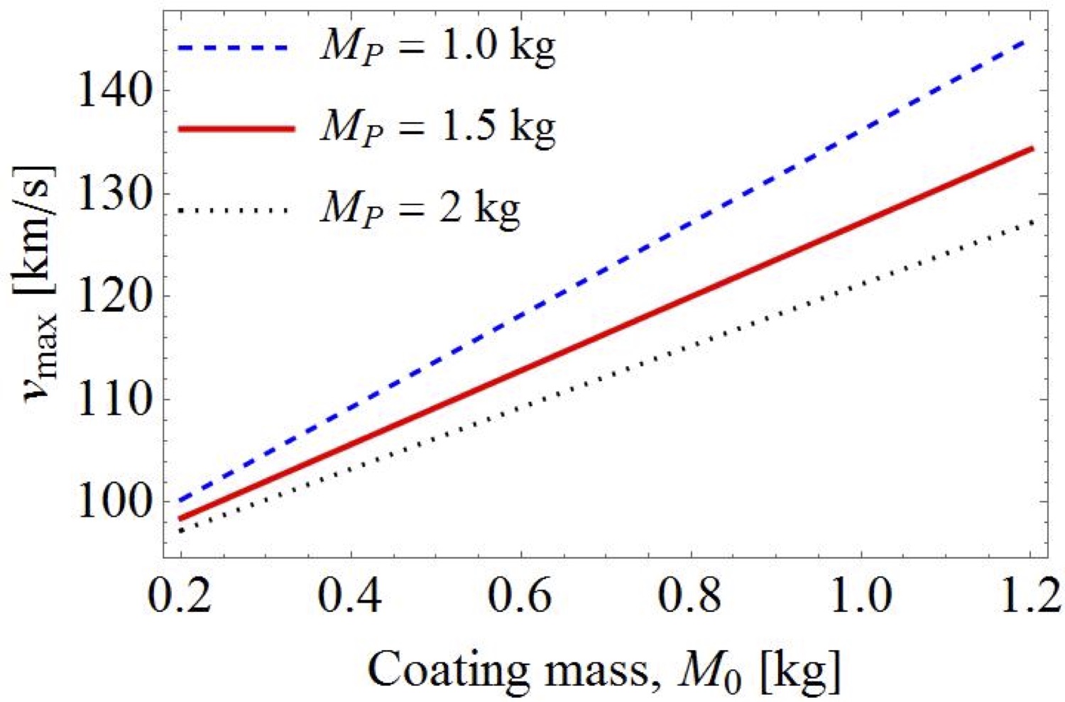
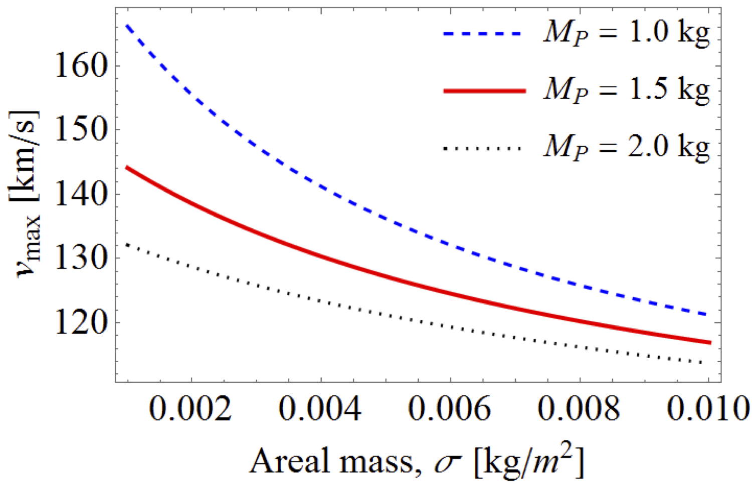
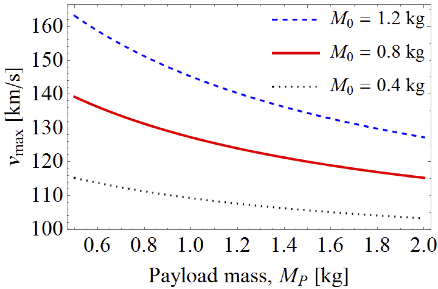
For the sake of brevity we will skip the orbital dynamics calculations, which are nothing but the application of well-known conventional formulas [11]. Instead, we go directly to the results that show the positive contribution of thermal desorption. We are assuming that the elliptical transfer is performed from Earth’s orbit to Jupiter’s orbit and the spacecraft can be in different heliocentric orbits. At the perihelion of the orbit where the sail should be deployed, the temperature corresponds to the desorption temperature of the coating material. We present the result for three perihelions: 0.1 AU, 0.2 AU and 0.3 AU. The corresponding temperature varies from 736 K at 0.3 AU to 1149 K at 0.1 AU [9]. The corresponding thermal velocities of carbon atoms vary from 1140 m/s to 1420 m/s. We consider the sail with the following parameters: m2, g/m2. If one deposits the coating mass of 0.2 kg to 1.2 kg for the sail area m2, the corresponding thickness of the coating layer varies from about m to m, assuming that the coating is carbon-based material with the avarage bulk density 1.74 . We next consider the dependence of the maximal sail velocity that it gains due to thermal desorption on the characteristic parameters of the coated solar sail. In particular, we study the dependence of the maximum velocity that the solar sail reaches due to the thermal desorption of coating on the deposit coating mass, , the areal density of the sail, and the mass of the payload, . The results of calculations are presented in Figs. 2, 3 and 4, respectively. Figure 2 presents the results for calculations of the dependence of maximal velocity on the coating mass for different payload masses ( AU, g/m. One can see that the increase of the coating mass leads to the increase of maximum velocity, while when the payload mass increases the decreases.
The dependence of the velocity of solar sail during the acceleration process due to thermal desorption when the sail is deployed at the perihelion of different heliocentric orbits is presented in Fig. 5. These calculations are performed for the coating mass kg and mass of payload kg. One can conclude that the closer the solar approach, the higher the velocity that can be achieved using thermal desorption.
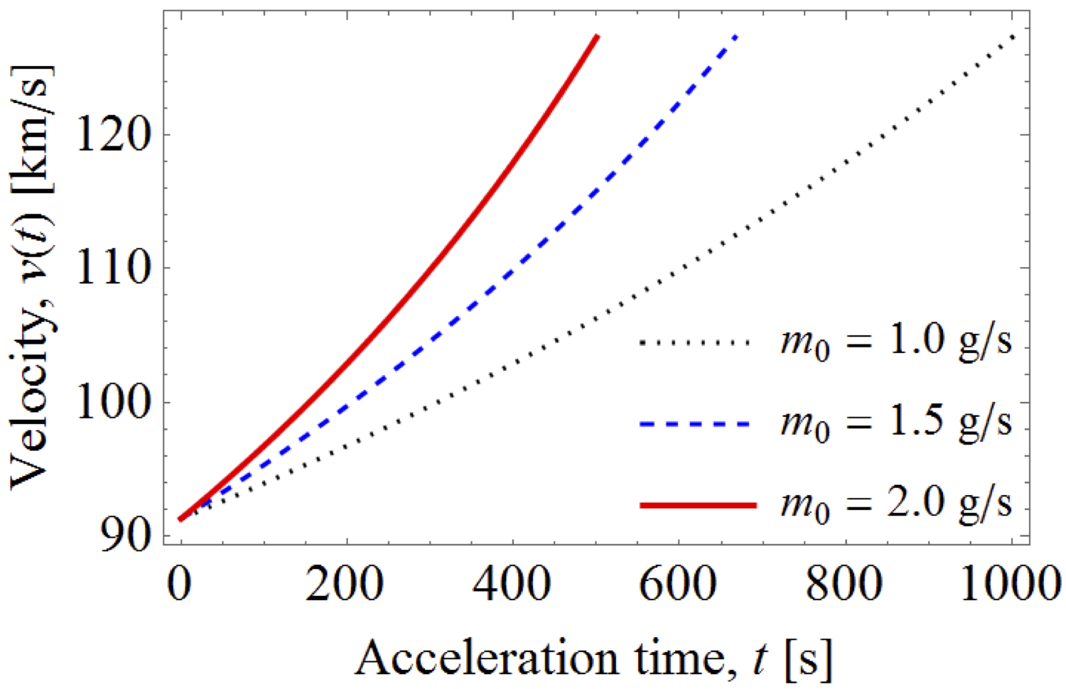
While the maximum velocity of the sail does not depend on the rate of thermal desorption, the time to reach the maximum velocity depends on the rate of this process. The time to reach the same maximum velocity decreases when the rate of the desorption increases. This is clearly illustrated in Fig. 6, which presents the dependence of the velocity of the sail on the rate of the desorption. When the desorption rate increases, the acceleration time decreases and the sail reaches a given in a shorter time.
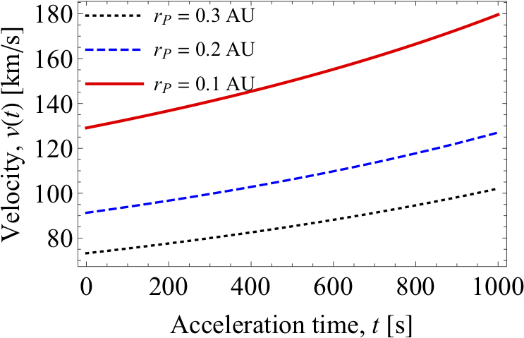
In Table 4, we present the results obtained for these three perihelion values. Calculations are performed for the coating mass kg required for the desorption and the mass of payload kg. In Table 4 is the sail velocity at perihelion, before desorption occurs. This velocity is calculated from the orbital dynamics of a conventional spacecraft for a proposed scenario. By contrast, the final velocity of the sail after the desorption time is calculated by using Eq. (8), which is the exact solution of Eq. (4) with time-depended coefficient . The final cruise speed is obtained from the application of the law of conservation of energy, and from it comes the distance travelled per year.
| Speed and Distance covered | ||||
|---|---|---|---|---|
| AU | 0.3 | 0.2 | 0.1 | |
| km/s | 73.24 | 91.28 | 129.11 | |
| km/s | 102.08 | 127.30 | 180.19 | |
| km/s | 107.72 | 134.09 | 189.78 | |
| AU/year | 22.71 | 28.26 | 40.01 | |
Conclusions
Investigation of Figs. 2 - 6 reveals that application of desorption results in high post-perihelion heliocentric solar sail velocities. Certainly, application of this technology with state-of-the-art sails can result in solar-system exit velocities in excess of 100 km/s.
At 100 km/s, or 20 AU/year, post-perihelion travel times to the vicinity of Kuiper Belt Objects will be less than 3 years. Factoring in time required for the Jupiter flyby to perihelion, target KBOs could be encountered less than 6 years after launch.
The solar-photon sail configuration considered in this paper is conservative and based on sails that have successfully operated in Low Earth Orbit or interplanetary space. Recent research reveals that much smaller sails could be incorporated with highly miniaturized chip-scale spacecraft [12, 13]. It is quite possible that a single dedicated interplanetary “bus” could deploy many chip-scale sails at perihelion. Sequential deployment of these sails could be timed to allow exploration of many small KBOs from a single launch.
References
- [1] G.L. Matloff, Deep-space Probes. To the Outer Solar System and beyond, second ed., Proxis Publishing, Chischester, UK, 2001.
- [2] R. Walker, D. Izzo, and C. de Negueruelo, ESA Advanced Concepts Team, Noordwijk, and N. Berend, E. Moreno, J-M Rualt, and R. Epenoy, J. of Spacecraft and Rockets 51 (2014) 946.
- [3] J. Cassibry, R. Cortez, M. Stanic, et al., J. Spacecraft and Rockets 52 (2015) 595.
- [4] G. Benford and J. Benford, Acceleration of sails by thermal desorption of coatings, Acta Astronautica 56 (2005) 593–599.
- [5] R.Ya. Kezerashvili, Space exploration with a solar sail coated by materials that undergo thermal desorption, Acta Astronautica 117 (2015) 231–237.
- [6] Y. Tsuda, O. Mori, R. Funase, H. Sawada, T. Yamamoto, T. Saiki, T. Endo, and J. Kawaguchi. Flight status of IKAROS deep space solar sail demonstrator. Acta Astronautica, 69 (2011) 833–840.
- [7] Y. Tsuda, O. Mori, R. Funase, H. Sawada, T. Yamamoto, T. Saiki, T. Endo, K. Yonekura, H. Hoshino, and J. Kawaguchi. Achievement of ikaros - japanese deep space solar sail demonstration mission. Acta Astronautica 82 (2013) 183–188.
- [8] L. Johnson, M. Whorton, A. Heaton, R. Pinson, G. Laue, and C. Adams. Nanosail-D: A solar sail demonstration mission. Acta Astronautica 68 2011 571–575.
- [9] E. Ancona and R.Ya. Kezerashvili, Temperature restrictions for materials used in aerospace industry for the near-Sun orbits, Acta Astronautica 140 (2017) 565–569.
- [10] E. Ancona and R.Ya. Kezerashvili, Orbital dynamics of a solar sail accelerated by thermal desorption of coatings, arXiv:1609.03131(2016) [physics.space-ph]; IAC 67, Guadalajara, Mexico, 2016, Paper ID: 32480.
- [11] R. R. Bate, D. D. Mueller, and J. E. White. Fundamentals of Astrodynamics. Dover Publications, Inc., 1971.
- [12] L. Weis, and M. Peck, “Active Solar Sail Designs of Chip-Scale Spacecraft:, Presented at 28th Annual AIAA/USU Conference on Small Satellites, Utah State University, Logan, Utah, August 4-7, 2014, Paper SSC14-X-6.
- [13] The 2015 NASA Technology Roadmaps, https://www.nasa.gov/offices/oct/home/ roadmaps/index.html