Wettability-independent droplet transport by Bendotaxis
Abstract
We demonstrate bendotaxis, a novel mechanism for droplet self-transport at small scales. A combination of bending and capillarity in a thin channel causes a pressure gradient that, in turn, results in the spontaneous movement of a liquid droplet. Surprisingly, the direction of this motion is always the same, regardless of the wettability of the channel. We use a combination of experiments at a macroscopic scale and a simple mathematical model to study this motion, focussing in particular on the time scale associated with the motion. We suggest that bendotaxis may be a useful means of transporting droplets in technological applications, for example in developing self-cleaning surfaces, and discuss the implications of our results for such applications.
pacs:
47.55.nb,46.25.-y,46.35.+zControl and transport of liquid droplets on small scales, where surface forces dominate, is of critical importance in applications including microfluidics, microfabrication and coatings Style et al. (2013); Squires and Quake (2005); Srinivasarao et al. (2001); de Gennes et al. (2004); Mastrangelo and Hsu (1993). Active processes including gradients in temperature Sammarco and Burns (1999); Pratap et al. (2008), applied electric potentials Mugele and Baret (2005) and mechanical actuation Prakash et al. (2008) have been used successfully to generate such fine scale control. Recently, however, there has been growing interest in generating droplet motion passively. This can be achieved using a fixed geometry, in which droplets move in response to tapering Kim and Weitz (2011); Reyssat (2014); Lv et al. (2014); Renvoisé et al. (2009); Guan et al. (2017). When the geometry is responsive (e.g. with deformable boundaries), however, more possibilities open up, including durotaxis Style et al. (2013) and tensotaxis Bueno et al. (2017), which rely on gradients in stiffness and strain of an underlying soft substrate, respectively, to control motion. Here we introduce a novel, passive droplet transport mechanism that takes advantage of the capillary-induced bending of a narrow channel whose walls are slender and hence deformable; we term this motion bendotaxis. Importantly, we shall demonstrate that the direction of bendotaxis is independent of wettability. This is in contrast to durotaxis, in which wetting and non-wetting droplets have been reported to move in opposite directions Bueno et al. (2018).
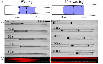
Figure 1(a) illustrates the mechanism behind bendotaxis: two, initially parallel, bendable walls are clamped at one end and free at the other, forming a two-dimensional channel. If a wetting droplet is introduced between the walls, the negative Laplace pressure deflects the walls inwards. The deformation is larger at the meniscus closer to the free end (referred to as ) than at the clamped end (). The pressure is therefore more negative at than at ; the resulting pressure gradient drives the droplet towards the free end. Provided the contact angles remain the same and the beams do not touch, this motion will continue until the droplet reaches the free end. For a non-wetting droplet introduced into the channel, the Laplace pressure is positive, pushing the beams away from one another but the resulting pressure gradient is again negative, driving the droplet towards the free end.
This mechanism is reproducible in a simple laboratory experiment. We fabricated channels using a rigid separator and glass coverslips. Figure 1(b) shows time-series of a wetting silicone oil droplet and of a non-wetting water droplet in such a channel. In both cases, the droplets move towards the free end of the channel. To observe the deflection of the coverslips, we compare their shapes in the final configuration with those prior to the introduction of the droplet (fig. 1(c)). In the wetting case, both coverslips are deflected inwards, while in the non-wetting case both are deflected outwards, in accord with our physical description. The observed deflections also provide evidence that motion is not simply caused by the weight of the droplet, which would cause the lower coverslip to deflect downwards in both cases. (Our neglect of gravity is justified in endnote47.)
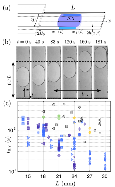
To gain insight into the dynamics of bendotaxis we performed a series of more detailed experiments: sections of borosilicate glass coverslips (Agar Scientific, Young’s modulus , thickness , width ) were first treated (see below) before being clamped with a separation to create an open-ended channel, as in fig. 2(a). The channel length is controlled by changing the clamping position (while maintaining a relatively long clamped section to ensure there is no intrinsic tapering, which would alter the dynamics Renvoisé et al. (2009); Reyssat (2014); Gorce et al. (2016)).
The treatment of the glass and the droplets used depended on the required wetting conditions: for the non-wetting case, the walls were sprayed with a commercial hydrophobic spray (Soft-99, Japan) and dip-coated with silicone oil V5 (Sigma-Aldrich, USA) forming a slippery lubricant-infused porous surface (SLIPS) Wong et al. (2011); Smith et al. (2013); Luo et al. (2017); endnote47. Droplets were formed from a water–glycerol mix (70 water by weight, dynamic viscosity , surface tension ); this combination of drop and lubricant liquids ensures a large advancing contact angle ( endnote47), low hysteresis (receding angle ) and a large enough drop:lubricant viscosity ratio that viscous dissipation occurs primarily within the droplet Keiser et al. (2017); endnote47.
In the wetting case, we pre-wetted the glass with silicone oil (pre-wetting was performed on both bare glass, as well as with glass pre-treated by hydrophobic spray to better retain the wetting film; we find no difference between these two cases in our experimental data endnote47). Droplets of silicone oils V50, V100, V350 and V500, were used to vary the dynamic viscosity in the range while maintaining . These droplets perfectly wet the pre-wetted glass but form a capillary bridge with well-defined menisci.
The droplet volume was systematically varied in the range , leading to different initial droplet lengths and, hence, different relative volumes (constant in each experiment). The wall separation at the free end is enforced to be during droplet deposition but removed shortly after, which corresponds to ; in this brief period immediately following deposition, droplet motion is negligible Mastrangelo and Hsu (1993); endnote47. The experiment is photographed from above, as in fig. 2(b), and the position of the leading meniscus, , is recorded and tracked using image analysis software in Matlab. (Note that the droplet volumes were chosen so that the drop spans the width of the channel, becoming effectively two-dimensional, fig. 2(b).)
To quantify the time scale of motion in a reproducible manner (independent of the initial droplet position), we measure the time, , taken for the droplet to pass from to the free end . This quantity is approximately independent of the initial condition, provided inertia is negligible. Here we present results for , which is arbitrary but covers a significant portion of the motion for which beam bending occurs over a length comparable to (a fact used in the following scaling arguments), whilst still allowing most experiments to be included.
Raw measurements of are presented in fig. 2(c), and indicate a strong dependence on both channel geometry and droplet viscosity. To gain theoretical insight, we first consider a scaling argument assuming a small relative volume, , which captures the combination of elasticity and capillarity involved. Droplet motion is driven by the Laplace pressure change that results from droplet-induced tapering of the channel (we assume a constant surface tension and contact angle at the leading and rear menisci and neglect the surface tension from the sides, shown to be relatively unimportant in a similar situation Kwon et al. (2008)). In a narrow channel, the pressure change across the droplet due to a tapering angle can be approximated as . Since the channel walls bend over a length comparable to (provided the drop is relatively far from the clamp), but are only subject to a Laplace pressure over the length of the drop, linear beam theory Howell et al. (2009) suggests that . (Here is the bending stiffness of the wall per unit width Audoly and Pomeau (2010); endnote47.) Therefore, the pressure gradient over the (small) droplet is estimated as
| (1) |
Lubrication theory Leal (2007) provides the timescale for a droplet of viscosity to move along the length of the beams as . When considered relative to a capillary timescale , this yields
| (2) |
The scaling (2) provides a reasonable collapse of the experimental data for all of the wetting data, see fig. 3 and fig. S1 endnote47. However, the non-wetting experiments show two families with a similar scaling trend but modified prefactors, which may be due to a change in the effective value of between measurements made on a single SLIPS and experiments in a narrow channel. A possible cause for such a change in the driving Laplace pressure is a thin oil layer ‘cloaking’ the droplet Schellenberger et al. (2015). Quantifying this is beyond the scope of the present study, but we note that the discrepancy in prefactor would be eliminated by a relatively small change in the effective contact angle of .
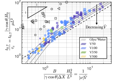
For moderate to large values of the abscissa in fig. 3 we observe the linear scaling of (2) (valid for ). However, at smaller values (larger ) the linear scaling appears to break down. To go beyond this scaling argument and determine the effect of finite droplet volumes , we formulate a detailed mathematical model. Combining lubrication theory and linear beam theory (and neglecting the weight and tension within the beam) leads to a nonlinear PDE for the deformed shape of the beams within the wetted region Aristoff et al. (2011); Taroni and Vella (2012); Duprat et al. (2011):
| (3) |
The shape of the channel wall out of contact with the droplet satisfies and depend on time only through the meniscus positions. At each meniscus we require continuity of shape, slope, moments and shear force, consistent with the assumption of a small aspect ratio, , used in lubrication theory Taroni and Vella (2012). The pressure jump between dry and wet portions of the beam is due to the Laplace pressure at the meniscus, so that
| (4) |
As before, we have assumed that the contact angles at the advancing and receding menisci are equal and constant. On the timescales considered here, evaporation is negligible endnote47 conservation of mass then requires
| (5) |
We apply clamped boundary conditions at , while the end is free, i.e. , , and . The problem is closed by specifying initial conditions for the beam shape, , and the meniscus positions , .
Asymptotic analysis of the problem (3)-(5) for shows that the beam deflection is small and that the drop length is approximately constant throughout the motion 111See Supplementary Information, which includes refs Schott AG ; Takamura et al. (2012); A Schneider et al. (2012); Yuan and Lee (2013); Onda et al. (1996); Canny (1986); Hu and Larson (2002); Zhornitskaya and Bertozzi (2000); Shampine (2007), for details of the experimental procedure, asymptotic analysis and numerical techniques.. The evolution of the meniscus positions are then governed by the ODEs
| (6) |
The ODE for may be solved to give the time taken to move from to as
| (7) |
Eqn (7) confirms the scaling result (2) and provides the appropriate pre-factor, which, with , corresponds to the black dashed line in fig. 3.
To facilitate numerical solutions of the full problem (3)-(5), we non-dimensionalize axial lengths by , the beam deformation by and time by the capillary timescale , introduced earlier. In addition to the relative volume , we identify a further dimensionless parameter
| (8) |
which represents the ability of the droplet surface tension to bend the channel walls. We refer to the parameter as a channel ‘bendability’, though it is also related to the reciprocal of the elastocapillary number Mastrangelo and Hsu (1993). Note that wetting drops have while non-wetting drops have , consistent with the sign of the pressure in equation (4).
The problem is fully specified by the values of , , and the initial condition , and can be solved numerically in Matlab using the method of lines Schiesser (1991); endnote47. The numerical solution determines the time taken for a droplet starting with to reach for different values of and i.e. we may write
| (9) |
The scaling law (2) shows that in the limit . The numerically-determined values of are plotted in fig. 3 for several values of (spanning the experimentally realized range). These results suggest that some of the discrepancy between experiments and the scaling prediction (7) are accounted for by the finite value of . The neglect of some physical aspects may also result in deviation of experimental results from the numerical solutions; surface defects, the presence of gravity and surface tension acting along the sides will, for example, influence the dynamics. Whilst we expect these to be relatively unimportant endnote47, they will introduce ‘noise’ into experimental results not accounted for by the model.
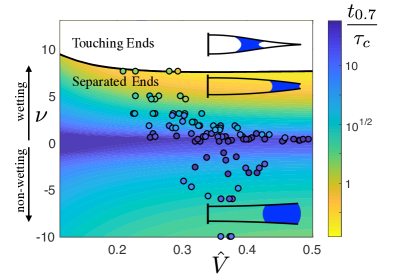
Numerical solutions of the dimensionless version of (3)–(5) yield the values of , which are shown in a color-map in fig. 4 with, schematics of the deformed channel shape. This demonstrates that, for fixed relative droplet volume , the time decreases as the absolute bendability increases (e.g. by decreasing the wall thickness , or Young’s modulus ). However, this is to be weighed against the possibility of the edges of the walls touching and trapping wetting drops indefinitely (see upper curve in fig. 4).
In this Letter, we have shown that a drop placed into a channel with deformable, but initially parallel, walls creates its own tapered channel, driving itself towards the free end, independent of the droplet wettability. We suggest that this universality of motion may find application in self-cleaning surfaces able to remove macroscopic contaminants Neinhuis and Barthlott (1997). In particular, surfaces are often textured at a microscopic scale to reduce adhesion and increase droplet mobility Bico et al. (1999); Quéré (2005). However, these properties can be impaired if liquid impregnates the texture Cheng and Rodak (2005). Tapering the texture has been suggested to reduce the internal fogging of some surfaces Mouterde et al. (2017), effectively expelling the soiling droplets automatically, but only works if these droplets are themselves non-wetting. A similar role has been suggested for the hairy coating on the legs of water-walking arthropods such as Gerris Regimis Wang et al. (2015). Here we have shown that under bendotaxis both wetting and non-wetting drops move to the free end of a rectangular channel, where they might naturally evaporate, be knocked off or even jump from the surface Wisdom et al. (2013). Rapid motion occurs for large values of the bendability, at the risk of trapping wetting droplets (fig. 4).
There remain many features of the system (including contact angle hysteresis three-dimensional geometry, and the behavior of the droplet at the end of the channel) that might complicate the picture of bendotaxis presented here. However, these complications may also provide further opportunities for passive droplet control with more sensitivity: for example, by tapering the undeformed channels slightly, we expect there would be a range of values of the bendability for which droplets would actually move towards the clamped end.
Acknowledgements.
This research was supported by the European Research Council under the European Horizon 2020 Programme, ERC Grant Agreement no. 637334 (DV) and the John Fell Fund, Grant no. BKD00020 (FB).References
- Style et al. (2013) R. W. Style, Y. Che, S. J. Park, B. M. Weon, J. H. Je, C. Hyland, G. K. German, M. P. Power, L. A. Wilen, J. S. Wettlaufer, et al., Proc. Natl. Acad. Sci. 110, 12541 (2013).
- Squires and Quake (2005) T. M. Squires and S. R. Quake, Rev. Mod. Phys. 77, 977 (2005).
- Srinivasarao et al. (2001) M. Srinivasarao, D. Collings, A. Philips, and S. Patel, Science 292, 79 (2001).
- de Gennes et al. (2004) P.-G. de Gennes, F. Brochard-Wyart, and D. Quéré, Capillarity and Wetting Phenomena: Drops, Bubbles, Pearls, Waves (Springer-Verlag New York, 2004).
- Mastrangelo and Hsu (1993) C. Mastrangelo and C. Hsu, J. Microelectromech. Sys. 2(1), 33 (1993).
- Sammarco and Burns (1999) T. S. Sammarco and M. A. Burns, React. Kinet. Catal. 45, 350 (1999).
- Pratap et al. (2008) V. Pratap, N. Moumen, and R. S. Subramanian, Langmuir 24, 5185 (2008).
- Mugele and Baret (2005) F. Mugele and J.-C. Baret, J. Phys. Condens. Matter 17, R705 (2005).
- Prakash et al. (2008) M. Prakash, D. Quéré, and J. W. M. Bush, Science 320, 931 (2008).
- Kim and Weitz (2011) S.-H. Kim and D. A. Weitz, Angew. Chem. 123, 8890 (2011).
- Reyssat (2014) E. Reyssat, J. Fluid Mech. 748, 641 (2014).
- Lv et al. (2014) C. Lv, C. Chen, Y.-C. Chuang, F.-G. Tseng, Y. Yin, F. Grey, and Q. Zheng, Phys. Rev. Lett. 113, 026101 (2014).
- Renvoisé et al. (2009) P. Renvoisé, J. W. M. Bush, M. Prakash, and D. Quéré, Europhys. Lett. 86, 64003 (2009).
- Guan et al. (2017) J. H. Guan, É. Ruiz-Gutiérrez, B. B. Xu, D. Wood, G. McHale, R. Ledesma-Aguilar, and G. G. Wells, Soft Matter 13, 3404 (2017).
- Bueno et al. (2017) J. Bueno, Y. Bazilevs, R. Juanes, and H. Gomez, Extreme Mech. Lett. 13, 10 (2017).
- Bueno et al. (2018) J. Bueno, Y. Bazilevs, R. Juanes, and H. Gomez, Soft Matter 14, 1417 (2018).
- Gorce et al. (2016) J.-B. Gorce, I. J. Hewitt, and D. Vella, Langmuir 32, 1560 (2016).
- Wong et al. (2011) T.-S. Wong, S. H. Kang, S. K. Y. Tang, E. J. Smythe, B. D. Hatton, A. Grinthal, and J. Aizenberg, Nature 477, 443 (2011).
- Smith et al. (2013) J. D. Smith, R. Dhiman, S. Anand, E. Reza-Garduno, R. E. Cohen, G. H. McKinley, and K. K. Varanasi, Soft Matter 9, 1772 (2013).
- Luo et al. (2017) J. T. Luo, N. R. Geraldi, J. H. Guan, G. McHale, G. G. Wells, and Y. Q. Fu, Phys. Rev. Applied 7, 014017 (2017).
- Keiser et al. (2017) A. Keiser, L. Keiser, C. Clanet, and D. Quéré, Soft Matter 13, 6981 (2017).
- Kwon et al. (2008) H.-M. Kwon, H.-Y. Kim, J. Puëll, and L. Mahadevan, J. Appl. Phys. 103, 093519 (2008).
- Howell et al. (2009) P. Howell, G. Kozyreff, and J. Ockendon, Applied Solid Mechanics, Cambridge Texts in Applied Mathematics (Cambridge University Press, 2009).
- Audoly and Pomeau (2010) B. Audoly and Y. Pomeau, Elasticity and Geometry (Oxford University Press, 2010).
- Leal (2007) L. G. Leal, Advanced Transport Phenomena: Fluid Mechanics and Convective Transport Processes (Cambridge University Press, 2007).
- Schellenberger et al. (2015) F. Schellenberger, J. Xie, N. Encinas, A. Hardy, M. Klapper, P. Papadopoulos, H.-J. Butt, and D. Vollmer, Soft Matter 11, 7617 (2015).
- Aristoff et al. (2011) J. M. Aristoff, C. Duprat, and H. A. Stone, Int. J. Nonlin. Mech. 46, 648 (2011).
- Taroni and Vella (2012) M. Taroni and D. Vella, J. Fluid Mech. 712, 273– (2012).
- Duprat et al. (2011) C. Duprat, J. M. Aristoff, and H. A. Stone, J. Fluid Mech. 679, 641 (2011).
- Schiesser (1991) W. Schiesser, The Numerical Method of Lines: Integration of Partial Differential Equations (Academic Press, 1991).
- Neinhuis and Barthlott (1997) C. Neinhuis and W. Barthlott, Ann. Bot. 79, 667 (1997).
- Bico et al. (1999) J. Bico, C. Marzolin, and D. Quéré, EPL 47, 220 (1999).
- Quéré (2005) D. Quéré, Rep. Prog. Phys. 68, 2495 (2005).
- Cheng and Rodak (2005) Y.-T. Cheng and D. E. Rodak, Appl. Phys. Lett. 86, 144101 (2005).
- Mouterde et al. (2017) T. Mouterde, G. Lehoucq, S. Xavier, A. Checco, C. T. Black, A. Rahman, T. Midavaine, C. Clanet, and D. Quéré, Nat. Mater. 16, 658 (2017).
- Wang et al. (2015) Q. Wang, X. Yao, H. Liu, D. Quéré, and L. Jiang, Proc. Natl. Acad. Sci. 112, 9247 (2015).
- Wisdom et al. (2013) K. M. Wisdom, J. A. Watson, X. Qu, F. Liu, G. S. Watson, and C.-H. Chen, Proc. Natl. Acad. Sci. 110, 7992 (2013).
- (38) Schott AG, Borosilicate glass properties, online; accessed 27-September-2018, URL www.schott.com/d/tubing/9a0f5126-6e35-43bd-bf2a-349912caf9f2/schott-algae-brochure-borosilicate.pdf.
- Takamura et al. (2012) K. Takamura, H. Fischer, and N. R. Morrow, J. Petr. Sci. Engng 98–99, 50 (2012).
- A Schneider et al. (2012) C. A Schneider, W. S Rasband, and K. Eliceiri, Nature Methods 9 (2012).
- Yuan and Lee (2013) Y. Yuan and T. R. Lee, in Surface science techniques (Springer, 2013), pp. 3–34.
- Onda et al. (1996) T. Onda, S. Shibuichi, N. Satoh, and K. Tsujii, Langmuir 12, 2125 (1996).
- Canny (1986) J. Canny, IEEE Trans. Pattern Anal. Mach. Intell. 8, 679 (1986).
- Hu and Larson (2002) H. Hu and R. G. Larson, J. Phys. Chem. B 106, 1334 (2002).
- Zhornitskaya and Bertozzi (2000) L. Zhornitskaya and A. L. Bertozzi, SIAM J. Numer. Anal. 37, 523 (2000).
- Shampine (2007) L. F. Shampine, ACM Trans. Math. Softw. 33, 26 (2007).