Large vacuum flux surfaces generated by tilted planar coils
Abstract
Helical equilibria can be generated by arrangements of planar coils similar to tokamaks, but without a central solenoid and with the toroidal field (TF) coils tilted with respect to the vertical. This is known from earlier numerical works, e.g. P.E. Moroz, Phys. Plasmas 2, 4269 (1995). However, such concept tends to need large coils (of low aspect ratio) but form small plasmas (of large aspect ratio). Here it is numerically shown that larger, more attractive vacuum flux surfaces -relative to the size of the device- can be generated by carefully optimizing the inclination of the TF coils and currents in the various coil-sets. Vacuum configurations of aspect ratios as low as 4 are found for 6 tilted TF circular coils. Higher numbers of TF coils have advantages (smaller effective ripple) and disadvantages (lower rotational transform, smaller plasma). Finally, the aspect-ratio of the vacuum flux surfaces is quantified as a function of the ratio of the coil-radius to the radial location of the coil-center. It is found that, in order to minimize , it is beneficial to interlink or marginally interlink the TF coils ().
Keywords:
1 Introduction
Modular coils in modern stellarators are characterized by complex shapes. In parallel with the development of faster and cheaper construction techniques, it is desirable that coil-shapes be simplified while fulfilling all other stellarator optimization criteria. These include but are not limited to minimized neoclassical and turbulent transport, improved energetic particle confinement, good ballooning stability, etc. Recent works in coil-simplification include the design of modular coils that are planar on their outboard side, to ease maintenance access and blanket-module replacement [1]. In another study, the REGCOIL code enabled coil-designs of reduced curvature (thus simpler to build, and subject to reduced electromagnetic stresses) compared to other numerical techniques, but generating the same magnetic field [2].
Heliotrons/torsatrons, on the other hand, feature helical coils as wide as , rather than . Here is the major radius of the plasma and is a quantity comparable with the minor radius of the plasma, but larger, to allow space for the blanket. Note that in a reactor 8-20 m (depending on the design) and 3m [3].
In brief, it would be desirable for optimized stellarator coils to be simpler, for example more planar, and for heliotron/torsatron coils to also be simpler, and more compact.
The heliac meets such criteria: it features circular toroidal field (TF) coils of diameter and only one large circular coil of diameter , in the midplane of the device. The TF coils are vertically oriented, but non-axisymmetrically arranged according to a helical magnetic axis. However, heliac experiments such as H-1 [4] and TJ-II [5] exhibit reduced confinement compared to other helical devices of comparable size. This is exemplified by the lower multiplying factor, , for TJ-II in the International Stellarator Scaling [6].
While in the heliac the helical axis is generated by helically displacing the coils, in another class of helical devices the TF circular coils are tilted.
In the present paper, after briefly reviewing such devices (Sec. 2.1), we lay out the motivation for investigating a particular sub-set in which the coils are planar, tilted with respect to the vertical, interlinked to each other, and the plasma current is negligible (Sec. 2.2). In particular, we consider configurations with =3-18 tilted TF coils. We optimize them for maximum plasma volume or, equivalently, minimum aspect ratio, as a function of the TF coils’ inclination and of the currents in the TF and poloidal field coil-sets. The rationale for such optimization is that the aspect ratio must be reasonably low for a stellarator reactor to be attractive. Indeed, after explaining the principle of rotational transform by tilted coils in Sec. 3 and describing the numerical method in Sec. 4, we obtain values as low as =4 in Sec. 5. In Sec. 5 we also analyze the dependence of and of the profiles of effective helical ripple and rotational transform upon the number of coils , coil-tilt and normalized coil location , defined in Sec. 4.
This is the first extensive optimization of this nature. To enable high-resolution scans of the large, multi-dimensional parameter space, only vacuum flux surfaces were computed in the present study. These can be considered low-beta approximations of plasma equilibria.
Equilibrium calculations at finite beta go beyond the scope of the present paper and are left as future work, but are expected to reveal even larger plasmas (lower aspect ratios), thanks to their finite bootstrap current. More generally, finite plasma currents are known to lead to larger plasma volumes [7] and, of course, higher rotational transform. Similar ideas underpinned the NCSX modular-coil quasi-axisymmetric stellarator design: the concept, since renamed QUASAR, self-consistently took advantage of finite boostrap-current to assist in generating rotational transform and confine large plasmas of low aspect ratio [8, 9].
2 Background and motivation
2.1 Brief review of tilted coil devices
In the first work of this kind [10] planar coils were tilted both around the vertical and around the “non-trivial” horizontal axis (the trivial axis being the axis of symmetry of the circular coil). The locus of the coil-centers was a circle. In another concept [11] the coils were helically displaced as in a heliac, but tilted and non-circular. Other arrangements of planar coils that generate helical fields can be found in Refs. [12, 13].
Starting in the late 1980’s, variants [14, 15, 16, 17, 18] of Ref. [10] started receiving a great deal of attention. These variants featured fewer TF coils than the original idea (ranging between 2 [15] and 9 coils [18], instead of 24 [10]). This allowed for simpler construction, larger confined volume, higher rotational transform, but also a higher degree of non-axisymmetry and more pronounced toroidal ripples. Another difference is that the coils were only tilted with respect to the vertical plane, i.e., around their non-trivial horizontal axes.
As first noted in [14, 16], these configurations are, in effect, heliotrons/torsatrons (currents flow in the same direction in all coils, unlike classical stellarators, where they are alternated). Their helical coils have poloidal mode number 1 like other heliotrons/torsatrons, but toroidal mode number 1 as well. Due to this peculiarity, the “helical” coils are, in fact, circular. In contrast, most other heliotrons/torsatrons have 5-10.
In some cases [14, 15, 16, 17] each TF coil was “interlinked” or “interlocked” to every other TF coil, as if all TF coils had been pushed toward a central column (similar to a spherical tokamak) and beyond. This resulted in coils of diameter comparable to the device diamater, as is typical of heliotrons/torsatrons. In other cases [14, 16, 17, 18] the TF coils were not interlinked and were smaller, of diameter , similar to a heliac.
Starting in the mid-1990’s, Moroz numerically investigated several non-interlinked configurations [18, 19, 20, 21, 22, 23, 24, 25]. In some of them the coils were planar [18, 19, 22], including non-circular shapes [18, 22]. In others they were non-planar [20, 21, 23, 24, 25, 26], e.g. helical on the inboard [24, 25] or outboard side [21, 23], as also proposed [27, 28, 29] and experimentally realized [30] elsewhere.
Some studies assumed a net plasma current [20, 21, 23, 25], others assumed 0 [18, 26], others still compared cases with and without plasma current [19, 24].
Finally note that, along with 50 modular non-planar coils, W7-X is equipped with 20 tilted planar coils. Of these, 10 (of the “PCA” type) are tilted in one direction with respect to the vertical, and the other 10 (of the “PCB” type) are tilted in the opposite direction, and by a different amount [31].
2.2 Tilted, interlinked, planar coil torsatrons
In the present paper we argue that planar, interlinked coils configurations with are particularly appealing, and we numerically optimize them for maximum plasma size (in a low , vacuum limit).
Planar coils are obviously appealing from a manufacturing point of view, because they are simpler to construct than other stellarator coils.
In most of the paper we restrict to interlinked coils, partly because of their relevance to the CNT and CIRCUS experiments at Columbia University and partly because, as it will be shown in Sec. 5.4, interlinked and marginally interlinked coils yield larger plasmas, of lower aspect ratio.
CNT is equipped with just two interlinked coils and two poloidal field or vertical field (VF) coils. CNT was the first device to toroidally confine non-neutral plasmas [32, 33, 34] and plasmas with various degrees of quasi-netrality [35]. Its focus has recently shifted to 3D diagnostic image inversion [36], error fields [37], high beta [38] and overdense microwave heating [39] in neutral stellarator plasmas.
CIRCUS [7] is equipped with six interlinked TF coils of adjustable tilt with respect to vertical, and two up-down symmetric pairs of poloidal field coils, denominated respectively VF and quadrupole field (QF) coils. CIRCUS aims at experimentally generating or amplifying rotational transform by using more than two tilted planar coils, for the first time. Here “generating” refers to generating a finite and creating flux-surfaces, even in the absence of plasma current (=0). “Amplifying” by means of tilted coils refers to obtaining a higher than if the coils were not tilted; a finite , however, is necessary to begin with (this could be an external rotational transform from non-axisymmetric coils, or could be due to 0). CIRCUS was originally conceived as a tokamak-torsatron hybrid in which a finite generates a finite and the tilted coils increase or amplify it (as if they imparted “kicks” to the helical field-lines, and thus twisted them even more) [7]. In the present paper, however, it is predicted that CIRCUS can operate as a pure torsatron as well and generate even in the absence of finite .
This is an intermediate step toward even higher numbers of tilted TF coils. High are attractive for tokamak-torsatron hybrids (0): compared with equivalent tokamaks adopting the same (say, =18), these hybrids are expected to generate more rotational transform in spite of requiring a 25-50% lower plasma current [7, 40], making disruptions less likely and less harmful. Incidentally, it is well-known that small fractions of external rotational transform dramatically reduce the disruptivity of tokamak and hybrid plasmas [41, 42]. Hence, plasmas confined by =18 tilted coils are expected to be significantly less disruptive than equivalent tokamak plasmas. In addition, hybrid tokamak-torsatron plasmas of high are more axisymmetric than equivalent tokamaks or torsatrons: the effective helical ripple is expected to be even smaller than in equivalent tokamak plasmas [7, 40] and much smaller than in typical stellarator and heliotron/torsatron plasmas, with benefits for confinement.
Finally, we restrict to current-free configurations that do not require a solenoid nor current drive, due to their attractiveness for steady state at high plasma density. Note that most current drive mechanisms tend to be inefficient at the high densities encountered in the high-density H-mode at W7-AS [43].
3 Physical principle of rotational transform generation by tilted planar coils
3.1 Interlinked coils
When the tilted coils are interlocked, it is intuitive that they are equivalent to a torsatron. To visualize this, imagine being a local observer at toroidal location inside the torus. Let us call “outer” and “inner” the regions at larger and smaller major radii , respectively, and color-code them in orange and green in Fig. 1a. The observer in will only see the “outer part” (orange) of coils centered at nearby locations (say, in a range ), and only the “inner part” (green) of nearly diametrically opposite coils, located at . The consequence is illustrated in Fig. 1c: the local observer has the perception of helical windings, all carrying current in the same direction (poloidally clockwise and toroidally counter-clockwise -that is, “pointing away from the observer”- in the specific example pictured). This is because if one takes poloidal cross-sections at incremental toroidal angles (not shown), the cross-sections of the coils will rotate in a definite poloidal direction.
Equivalently, the “unwrapped” coil-winding surface looks like in Fig. 1e: all coil-currents have the same helicity everywhere.
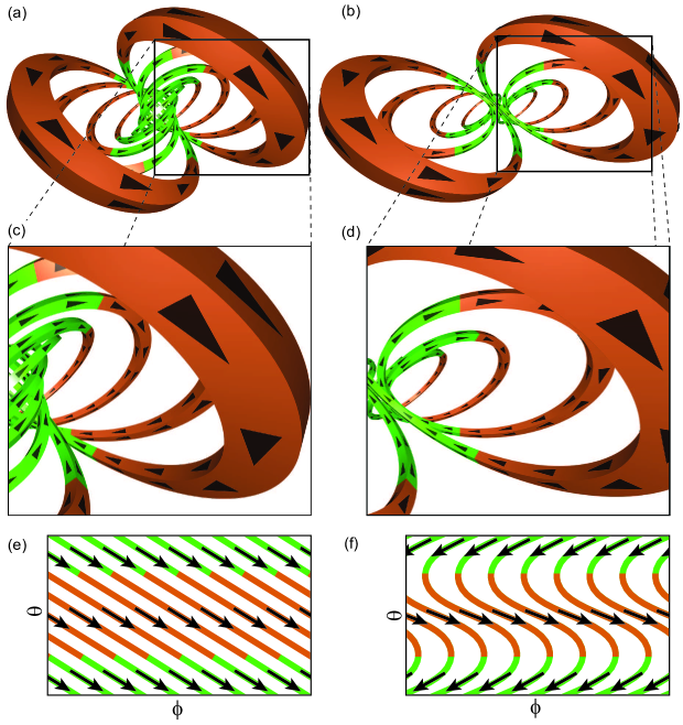
3.2 Non-interlinked coils
In the case of non-interlinked coils (Fig. 1b), the observer in only sees local coils (at toroidal locations or closer), but not the remote ones. Now consider the poloidal cross section of a single tilted coil. This intersects a vertical plane at two locations. At those two locations, the current obviously flows in opposite directions. If one now considers several coils, all tilted in the same direction, and takes poloidal cross-sections at incremental toroidal angles, all coil cross-sections will move upward or all downward. This is not a helical device, where all coil cross-sections move poloidally clockwise, or counter-clockwise. More specifically, this is neither a torsatron (where all currents point in the same helical direction and verse) nor a classical stellarator (where adjacent coil-currents have alternate verses). Rather, some currents “point toward the observer” (see top left of Fig. 1d). Their helicity is inconsistent with the other currents in Fig. 1d. Equivalently, the unwrapped coil-winding surface looks like in Fig. 1f: each TF coil contributes currents of a certain helicity on the outboard side (orange) and of opposite helicity on the inboard side (green).
The key, however, is that (1) these coils generate a helical magnetic axis and (2) the plasma column rotates and changes shape with . Both features (1) and (2) were noticeable in Fig. 2 of Ref. [18]. Incidentally, that figure referred to 0-0.35 in a device with interlinked coils, but is easily generalized to 0-0.7 by stellarator symmetry. Features (1) and (2) will also be visible in Fig. 4 of the present article, also for interlinked coils. Points (1) and (2) are two of the three sufficient conditions to generate helical transform, the third one being finite plasma current [44, 45]. Biot-Savart calculations confirm the generation of helical fields, even when the coils are not interlinked [14, 16, 17, 18] and codes confirm the existence of equilibria [19, 20, 21, 22, 23, 24, 25].
3.3 Coil-tilt always amplifies rotational transform, but only generates it under special circumstances
Note that arbitrary sets of poloidal field coils and tilted TF coils (whether interlinked or not), energized with arbitrary currents, only generate infinitesimal vacuum flux surfaces, or none at all. They would still “amplify” , in the sense that, if field-lines are already twisted by other means (Ohmic plasma current, current drive, effect of bootstrap current, external rotational transform), tilted planar coils can give them further “kicks” and twist them even more. However, in order for these configurations to act as “sources” or “generators” of rotational transform, the TF coil inclination and the coil-currents must be properly chosen, as it will be shown in Sec. 5.
Finally, because all TF coils are tilted in the same direction and energized in the same direction, they generate a net vertical field similar to heliotrons/torsatrons and unlike stellarators, calling for compensation by VF coils.
3.4 Alternative point of view
Consider the volume enclosed by tilted TF coils, whether interlinked (Fig. 1a) or not (Fig. 1b). To clarify, in the case of the coils being interlinked, the “inboard side” of the volume of interest (lying at smaller major radii) is bound by the coils’ “outside” (the side facing larger minor radii of the coils).
Consider now an arbitrary location within this volume. In that location, all the tilted TF coils, whether close or diametrically opposite, generate toroidal fields of the same sign. The same is true in any other arbitrary location. That is, the sign of the toroidal field is uniform. The vertical field from the TF coils, on the other hand, is sheared in the major radius direction, and changes sign near the inboard wall.
The VF and, to some extent, the QF coils superimpose an additional vertical field, nearly uniform. This moves the magnetic null (roughly the magnetic axis) to outer radii.
The QF and, to some extent, the VF coils add a radial field that is vertically sheared, and changes sign at the midplane of the device.
These vertically sheared and radially sheared combine to create a poloidal field , where is the minor radius. The latter, in combination with , creates nested flux surfaces with rotational transform.
As for the toroidal dependence, both and oscillate with period in direction , but out of phase with each other. This results in a helical magnetic axis, also generating rotational transform. Note that, for higher , the oscillations become more frequent but also smaller in amplitude, to the detriment of rotational transform (which might partly explain why the plasma becomes smaller). For , the magnetic axis is perfectly axisymmetric.
The considerations made in the present Section, 3.4, apply equally to interlinked and non-interlinked configurations.
4 Numerical method
One of the goals of this study is to minimize the plasma aspect-ratio as a function of the TF coil-tilt and of the TF, VF and QF coil-currents or, equivalently, of coil-current ratios. Two such ratios suffice, because the goal is to maximize the plasma volume or, equivalently, minimize the aspect ratio. Therefore, the field topology is important, but the field magnitude is not, and is defined on the net of a scaling factor.
For this reason, for each combination of current-ratios and tilts we identified the Last Closed Flux Surface (LCFS) by means of a field-line tracer and computed the volume of the enclosed plasma and the toroidally averaged major radius of the magnetic axis. From these pieces of information we deduced the minor radius of the plasma, and, ultimately, its aspect ratio .
The field-line tracer used was FIELDLINES [46]. As usual this was interfaced to the MAKEGRID Biot-Savart code, but with ad hoc modifications. Namely, normally the code discretizes the current-carrying coils in short current filaments and numerically integrates the Biot-Savart law to compute the magnetic field in a location of interest. This is appropriate for complicated 3D coils. Here, however, similarly to Moroz in his UBFIELD field-line tracing code [18], we took advantage of the coils being circular and the generated field being known analytically [47, 48, 49]:
| (1) | |||||
| (2) |
Here and are cylindrical coordinates relative to the coil center, and are complete elliptic integrals of the first and second kind, respectively [50] and
| (3) | |||||
| (4) | |||||
| (5) |
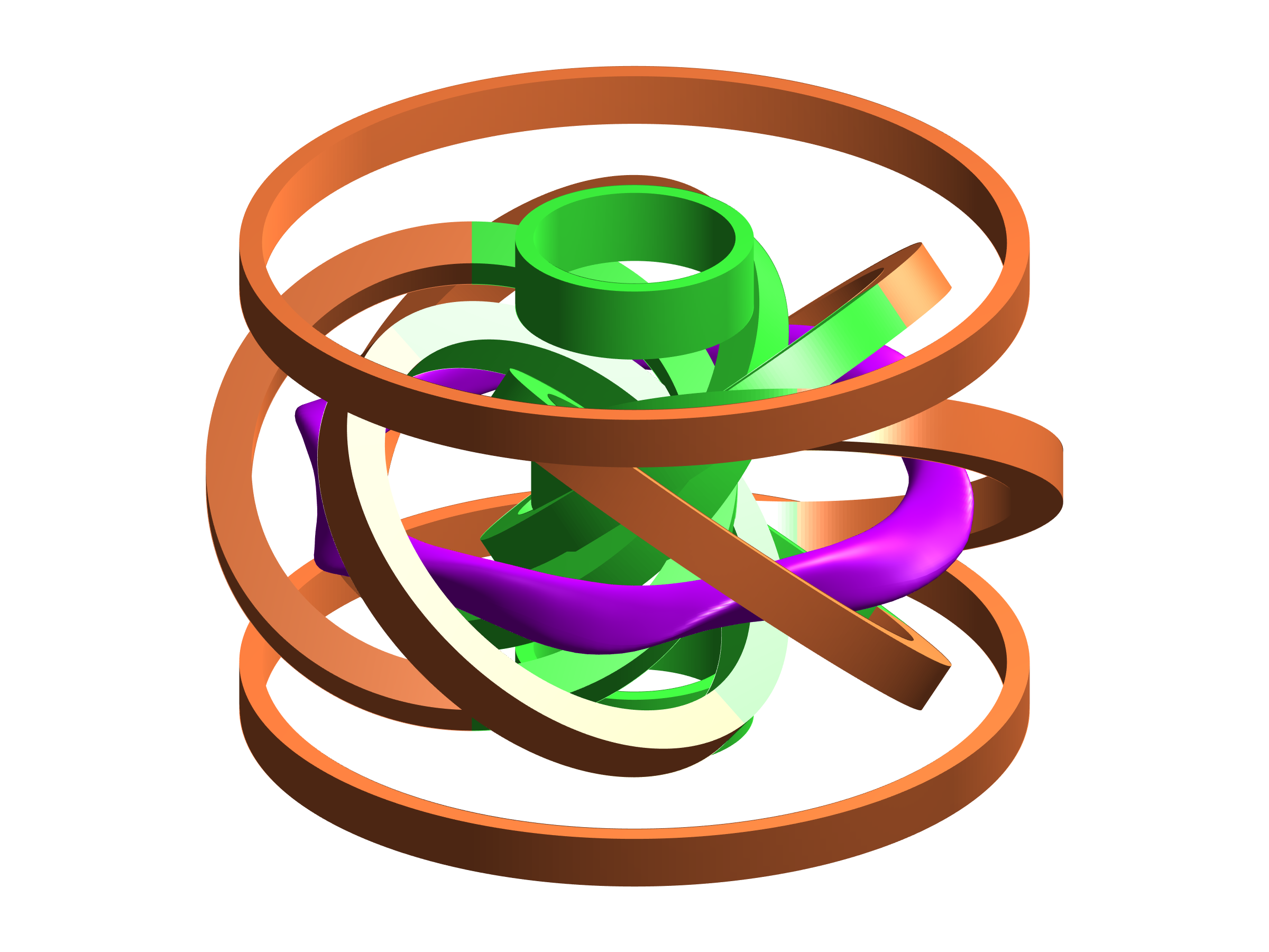
All coils in the present paper were modeled as finite-width arrays of the circular filaments just described. The cross-sections (length radial width) are 3.53.0 cm for the TF coils, 3.41.5 cm for the VF coils, and 5.01.2 cm for the QF coils. The size and relative position of the coils and the plasma is illustrated in Fig. 2 in the case of CIRCUS, featuring 6 tilted coils. Further details can be found in Ref. [7].
This semi-analyitic approach sped up the calculations for a single coil configuration by nearly two orders of magnitude, which allowed investigating more configurations in the same amount of time. This resulted in broad, fine scans of the parameter space. In particular, for each choice of the number of TF coils, , and their tilt angle with respect to the vertical, , we numerically scanned the coil-current ratios / and /.
Various field-lines were traced for each combination of , and . In the present article all TF coils are tilted by the same angle ; we do not consider the case in which they could be tilted by different amounts. The quantity is defined as the ratio between the major radius at which the TF coils are centered, and the radius of the TF coils. This ’normalized coil location’ is a measure of how interlinked the coils are (interlinked for , not interlinked for ). We will sometimes refer to it as ’coil aspect ratio’ (not to be confused with the ratio of the coil radius to the coil half-thickness). It is necessarily lower than the plasma aspect ratio , although ideally it should not be much lower: means that the TF coils are much larger than the poloidal cross-section of the plasma.
Field-lines were traced with such a numerical tolerance that, even after hundreds of toroidal turns, they are uncertain to less than 1mm.
The LCFS was identified as the outermost laminar surface outside of which field-lines are open and reach the boundary of the computational domain. Such identification took place in two parts: a 30-step coarse scan to isolate a promising radial interval, followed by a 30-step fine scan in that interval. This can yield a precision of up to one part in 900 at the cost of tracing just 60 field-lines (“up to” because for redundancy the interval examined in the fine scan was wider than the interval identified in the coarse scan). The idea is easily generalized to a bisection method (repetitive 2-step scans, zooming more and more on the LCFS).
5 Numerical results
5.1 6-coil configuration
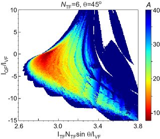
The CIRCUS device [7] features six TF coils of inclination adjustable in the range , relative to the vertical. Each TF, VF and QF coil consists of 69, 54 and 56 turns, respectively. , and denote the total currents in ampere-turn At, not in A. Fig. 3 presents the plasma aspect ratio as a function of the coil current-ratios, for . is replaced by to isolate the vertical field component generated by the TF coils and multiply it by the number of coils.
In this as well as in Figs. 4-8, the normalized radial location of the TF coils was set to 0.67, as in CIRCUS [7].
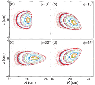
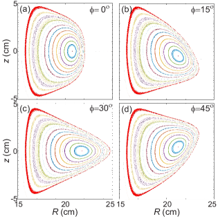
The lowest aspect ratio for this choice of , 7.8, is obtained for =0.35 and . The corresponding flux surfaces are plotted in Fig. 4 for the specific dimensions of the CIRCUS table-top device.
Striations in Fig. 3 and in similar contours in Figs. 5, 7 and 9 are due to rational surfaces near the LCFS.
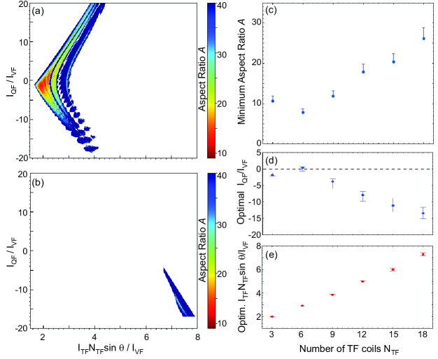
5.2 Dependence on number of TF coils
Numerical scans of the type presented in Fig. 3 were performed for CIRCUS-like configurations with varying numbers of TF coils, all the rest remaining equal. Contours of are shown in Fig. 5a-b for the lowest and highest value considered, =3 and =18. Contours for other values of are not shown for brevity, but the results of the scan, in increments =3, are summarized in Fig. 5c: the lowest is plotted for each as a function of the coil-current ratios. The tendency is for to increase with . This is partly due to a decrease in ripple, leaving less space for the plasma to “bulge out”, which makes the plasma more axisymmetric, but also smaller. The data point for 3 is an outlier. This could be due to the configuration being so non-axisymmetric, in that case, that the VF generated by simple circular (axisymmetric) VF and QF coils cannot effectively balance the highly non-axisymmetric VF generated by the few tilted TF coils. It is speculated that the issue could be ameloriated by properly shaped non-circular VF and QF coils.
It should be noted that the VF and QF coil-positions were kept constant. It is possible that their optimization (for instance, by moving the coils closer to the plasma as this gets smaller and smaller) could have enlarged and reduced , but at increased computational cost.
Flux-surfaces very similar to those shown in Fig. 4 were obtained for different , but are not shown for brevity. The main difference was that increasing resulted in smaller flux-surfaces and, of course, shorter toroidal periods 360.
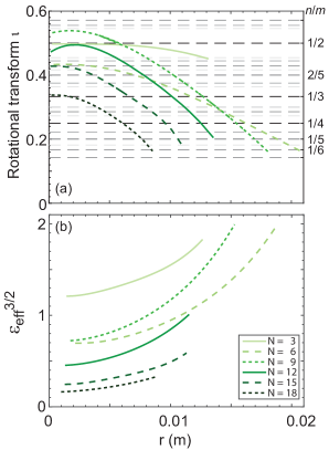
Plotted in Fig. 6 are the radial profiles of and , for various . The profiles were computed with FIELDLINES and found in agreement with profiles from the equilibrium code VMEC [51], used here at infinitesimal density and beta. The profiles, instead, were computed using NEO [52]. The values of are not as low as in a previous paper dedicated to tokamak-torsatron hybrids () with tilted coils [7]. A possible explanation lies in the fact that the torsatron plasmas discussed here () form at outer radii, closer to the outboard coil boundaries, where ripples are more pronounced.
Higher values of make the plasma more axisymmetric. The advantage is that the effective helical ripple becomes smaller. The disadvantage is that the vacuum rotational transform decreases as well, although it remains acceptably high even at =18 (, comparable with the earlier W7-AS). Note that the profile peaks at the center, not at the edge. In this it differs from typical stellarators and torsatrons, and is more similar to tokamaks. Also note that the magnetic shear is high and the profile crosses several low-order rational values, . Many magnetic islands can form as a result, but all small (similar to the strategy of LHD and other heliotrons, and opposite to the philosophy of the Wendelstein stellarator line).
5.3 Dependence on coil tilt
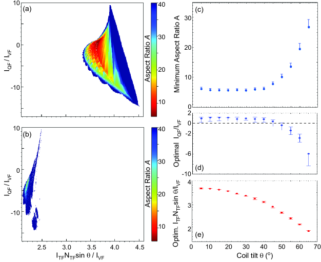
Next, numerical scans were performed for CIRCUS-like configurations with 6 TF coils for tilt-angles varying from (Fig. 7a) to (Fig. 7b) in steps of , all the rest remaining equal.
The plot in Fig. 7c exhibits a broad minimum of with respect to , with the very minimum obtained at .
For very small , however, in spite of being attractively low, the rotational transform is unattractively low (Fig. 8a). This is because barely tilted coils are nearly indistinguishable from pure TF coils: they only generate toroidal field and no rotational transform.
For large tilts (), on the other hand, the field is nearly entirely vertical, and the torus becomes oblated (basically, vertically “squeezed”). As a result, the plasma volume vanishes (Fig. 7c).
As noted in Sec. 5.2, optimizing the locations of the VF and QF coils instead of keeping them fixed (e.g., moving them closer to smaller plasmas) could increase and reduce . However, it would also increase the dimensionality of the scan and its computational cost.
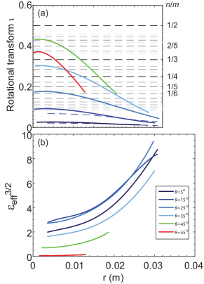
Plotted in Fig. 8 are the radial profiles of and , for various . For the TF coils are nearly vertical, similar to a tokamak. Not surprisingly, the corresponding is very small. More tilted coils impart higher rotational transform, reaching the maximum at about . Beyond that, decreases again, possibly due to the plasma-shape oblation mentioned above. Higher tilts tend to yield lower as well. This is ascribed to the field-line having less space to bulge out and deflect back in again.
5.4 Dependence on coil aspect ratio
The third parameter scanned is the normalized coil location or coil aspect ratio, . As mentioned before, this is defined as the ratio between the major radius at which the TF coils are centered, and the radius of the TF coils. Here we fix m and scan . Unlike , this ratio can take values , corresponding to the coils being interlinked.
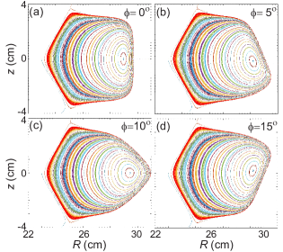
Fig. 9 summarizes the results of the scan for . Of particular interest is that the largest plasma volumes (lowest aspect ratio) are obtained for (moderately interlinked coils), for , whereas for the lowest is obtained for (marginally interlinked coils). The corresponding flux surfaces are plotted respectively in Fig. 10 and 11.
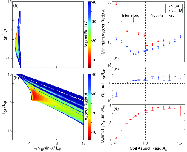
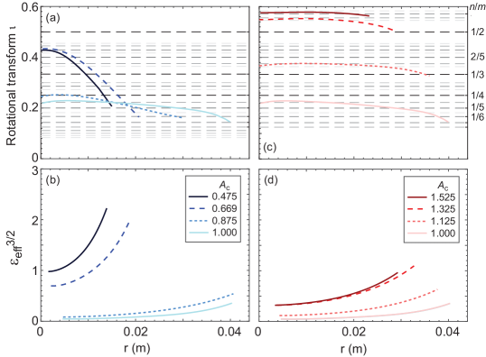
In addition, yields the lowest effective ripple (Fig. 12b and d) but also one of the lowest rotational transform (Fig. 12a and c).
Note that, for any given , there is a theoretical minimum below which cannot be reduced. This is because the aspect ratio of the plasma is necessarily larger than the aspect ratio of the coil-winding surface (), which is related to as follows. For the tilted coils are Villarceau circles for a toroidal surface spanning , hence the coil-winding surface has major radius , minor radius and aspect ratio . When instead , it is simply , and . These lower limits are not plotted in Fig. 9c, partly for simplicity and partly because they are quite small: for -1.7 they vary in the range 1-2.5.
6 Discussion and conclusions
As noted above, tilted-coil configurations are effectively torsatrons of . However, the present study might have implications for helical devices in general: it is speculated that planar coils can realize stellarator equilibria as well. It is also speculated that optimized configurations exist, whose coils are more tilted and “more planar” than typical modular coils in optimized stellarators (in general less coil-shaping implies less rotational transform, but this is compensated for by increased coil-tilt, as per Fig. 8). In fact, some planar tilted coils are already used in W7-X, as mentioned in Sec. 2.1.
A possible metric of non-planarity is the root-mean-square deviation of the coil from a plane, normalized to the coil diameter or perimeter. Its minimization could be incorporated in the set of stellarator optimization criteria, with a relative weight that will depend on coil-manufacturing times and costs.
This might seem in contrast with the complexity of the coil-winding surface (CWS) in W7-X, HSX and other optimized stellarators. However, arbitrary current-patterns on an arbitrary CWS can always be approximated with planar current-filaments belonging to multiple planes intersecting the CWS. A high enough number of adequately inclined planes should approximate any current-pattern. If this results in coil-intersections, the intersecting coils can be slightly displaced with respect to each other in the minor radius direction (equivalent to introducing a second, concentric CWS). Alternatively, the interesections can be removed in the same way as intersecting TF and helical coils are replaced by modular coils. In other words, the coils can be piecewise planar.
To summarize and conclude, a numerical field-line tracer was used here to compute the vacuum flux-surfaces generated by a variable number of toroidal field coils, tilted by a variable angle . Various normalized coil locations were also considered, defined as the ratios between the major radius at which the coils are located, and the coil radii. It was found that, for a particular geometry (, and , which can probably be optimized even further) and coil-currents ( and ), tilted coil configurations can confine relatively large plasmas, of aspect ratio as low as .
Only vacuum flux-surfaces were computed in the present study, to enable high-resolution scans of these and other parameters (for instance, the coil-currents). The results can be trusted in the low beta, =0 limit. Based on other works available in the literature [19, 20, 23, 24, 25], including ours [7], it is expected that finite bootstrap current and/or of a finite induced or driven should lead to an even lower , which is left as future work.
Acknowledgments
The authors thank W. Reiersen and D. Spong (ORNL) for the encouragement and fruitful discussions, as well as E. Maragkoudakis (TU Eindhoven) and M. Werl (TU Wien) for carefully reading and discussing the manuscript.
References
References
- [1] D. A. Gates, A. H. Boozer, T. Brown, J. Breslau, D. Curreli, M. Landreman, S. A. Lazerson, J. Lore, H. Mynick, G. H. Neilson, N. Pomphrey, P. Xanthopoulos, and A. Zolfaghari. Recent advances in stellarator optimization. Nucl. Fusion, 57:126064, 2017.
- [2] M. Landreman. An improved current potential method for fast computation of stellarator coil shapes. Nucl. Fusion, 57:046003, 2017.
- [3] A. Sagara, Yu. Igitkhanov, and F. Najmabadi. Fusion Eng. Design, 85:1336, 2010.
- [4] B. D. Blackwell, J. H. Harris, J. Howard, M. G. Shats, C. Charles, S. M. Collis, H. J. Gardner, F. J. Glass, X. Hua, Michael, et al. Overview and Results from the H-1 National Facility. In I. S. Falconer, R. L. Dewar, and J. Khachan, editors, Plasma Physics, volume 669 of American Institute of Physics Conference Series, page 158, June 2003.
- [5] J. Sánchez, M. Acedo, D. Alegre, A. Alonso, J. Alonso, P. Álvarez, J. Arévalo, E. Ascasíbar, A. Baciero, D. Baião, et al. Nuclear Fusion, 51(9):094022, September 2011.
- [6] H. Yamada, J. H. Harris, A. Dinklage, E. Ascasibar, F. Sano, S. Okamura, J. Talmadge, U. Stroth, A. Kus, S. Murakami, et al. Nucl. Fusion, 45:1684, 2005.
- [7] A.W. Clark, M. Doumet, K.C. Hammond, K.C. Kornbluth, D.A. Spong, R. Sweeney, and F.A. Volpe. Fusion Eng. Design, 81:2732, 2014.
- [8] M C Zarnstorff, L A Berry, A Brooks, E Fredrickson, G-Y Fu, S Hirshman, S Hudson, L-P Ku, E Lazarus, D Mikkelsen, et al. Plasma Phys. Control. Fusion, 43(12A):A237, 2001.
- [9] A.S. Ware, D.A. Spong, L.A. Berry, S.P. Hirshman, and J.F. Lyon. Fusion Sci. Technol., 50:236, 2006.
- [10] A.V. Georgievskij, V.E. Ziser, V.V. Nemov, V.G. Peletminskaya, D.P. Pogozhev, Yu.F. Sergeev, M.N. Skoblik, and A.A. Shishkin. Nucl. Fusion, 14:79, 1974.
- [11] A. Reiman and A. Boozer. Phys. Fluids, 26:3167, 1983.
- [12] S.N. Popov and A.P. Popryaduhin. Sov. Phys. Tech. Phys., 11:284, 1966.
- [13] S. Rehker and H. Wobig. In Proc. 6th European Conf. on Controlled Fusion and Plasma Physics, Moscow 1973, volume 1, page 117. European Physical Society, Petit-Lancy, Switzerland, 1973.
- [14] V.E. Bykov, E.D. Volkov, A.V. Georgievskij, Yu.K. Kuznetsov, S.A. Martynov, V.G. Peletminskaya, K.S. Rubtsov, V.A. Rudakov, Yu.F. Sergeev, A.V. Khodyachikh, and A.A. Shishkin. In Proc. 12th IAEA International Conf. on Plasma Physics and Controlled Nucl. Fusion Research, Nice 1988, volume II, page 403. International Atomic Energy Agency, Vienna, 1989.
- [15] T. N. Todd. Plasma Phys. Control. Fusion, 32:459, 1990.
- [16] V.E. Bykov, E.D. Volkov, V.P. Vorobiova, A.V. Georgievskij, Yu.K. Kuznetsov, S.A. Martynov, V.G. Peletminskaya, V.A. Rudakov, Yu.F. Sergeev, M.A. Khatzhmuradov, and A.V. Khodyachikh. In Proc. IAEA Technical Committee Meeting and 8th Stellarator Workshop, Kharkov 1991, page 441. International Atomic Energy Agency, Vienna, 1991.
- [17] A.V. Georgievskij, S.A. Greek, A.I. Lysojvan, V.E. Moiseenko, I.S. Pinchuk, V.A. Rudakov, V.V. Nemov, and M.A. Khatzhmuradov. In Proc. IAEA Technical Committee Meeting Stellarator and Other Helical Systems, Garching 1993, page 480. International Atomic Energy Agency, Vienna, 1993.
- [18] P.E. Moroz. Phys. Plasmas, 2:4269, 1995.
- [19] P.E. Moroz. Fusion Sci. Technol., 30:40, 1996.
- [20] P.E. Moroz. Phys. Plasmas, 3:3055, 1996.
- [21] P.E. Moroz. Phys. Lett. A, 236:79, 1997.
- [22] P.E. Moroz. Plasma Phys. Control. Fusion, 39:1841, 1997.
- [23] P.E. Moroz. Nucl. Fusion, 37:1045, 1997.
- [24] P.E. Moroz. Plasma Phys. Control. Fusion, 40:1127, 1998.
- [25] P.E. Moroz. Phys. Lett. A, 243:60, 1998.
- [26] P.E. Moroz. Phys. Rev. Lett., 77:651, 1996.
- [27] H.P. Furth and C.W. Hartman. Phys. Fluids, 11:408, 1968.
- [28] A.H. Boozer, T.K. Chiu, R.L. Dewar, H.P. Furth, J.A. Goree, J.L. Johnson, R.M. Kulsrud, D.A. Monticello, , G. Kuo-Petravic, G.V. Sheffieled, and OTHERS. In Proc. 9th IAEA International Conf. on Plasma Physics and Controlled Nucl. Fusion Research, Baltimore, 1982, volume III, page 129, Vienna, 1983. International Atomic Energy Agency.
- [29] W.A. Cooper, T.N. Todd, S. Allfrey, T.C. Hender, and D.C. Robinson. Plasma Phys. Control. Fusion, 42:1105, 2000.
- [30] T Oishi, K Yamazaki, H Arimoto, K Baba, M Hasegawa, and T Shoji. Journal of Phys.: Conf. Series, 511(1):012042, 2014.
- [31] T. Andreeva, T. Bräuer, V. Bykov, K. Egorov, M. Endler, J. Fellinger, J. Kißlinger, M. Köppen, and F. Schauer. Tracking of the magnet system geometry during wendelstein 7-x construction to achieve the designed magnetic field. Nucl. Fusion, 55(6):063025, 2015.
- [32] T. S. Pedersen, A. H. Boozer, J. P. Kremer, R. G. Lefrancois, W. T. Reiersen, F. D. Dahlgren, and N. Pomphrey. The Columbia Nonneutral Torus: a new experiment to confine nonneutral and positron-electron plasmas in a stellarator. Fusion Sci. Technol., 46:200, 2004.
- [33] J. P. Kremer, T. S. Pedersen, R. G. Lefrancois, and Q. Marksteiner. Experimental confirmation of stable, small-debye-length, pure-electron-plasma equilibria in a stellarator. Phys. Rev. Lett., 97:095003, 2006.
- [34] P. W. Brenner, T. S. Pedersen, J. W. Berkery, Q. R. Marksteiner, and M. S. Hahn. Magnetic surface visualizations in the Columbia Non-Neutral Torus. IEEE Transactions on Plasma Science, 36(4):1108, 2008.
- [35] X. Sarasola and T. S. Pedersen. First experimental studies of the physics of plasmas of arbitrary degree of neutrality. Plasma Phys. Controlled Fusion, 54:124008, 2012.
- [36] K. C. Hammond, R. R. Diaz-Pacheco, Y. Kornbluth, F. A. Volpe, and Y. Wei. Onion-peeling inversion of stellarator images. Review of Scientific Instruments, 87:11E119, 2016.
- [37] K. C. Hammond, A. Anichowski, P. W. Brenner, T. S. Pedersen, S. Raftopoulos, P. Traverso, and F. A. Volpe. Experimental and numerical study of error fields in the CNT stellarator. Plasma Physics and Controlled Fusion, 58:074002, 2016.
- [38] K. C. Hammond, S. A. Lazerson, and F. A. Volpe. High- equilibrium and ballooning stability of the low aspect ratio CNT stellarator. Physics of Plasmas, 24:042510, 2017.
- [39] K C Hammond, R R Diaz-Pacheco, A Köhn, F A Volpe, and Y Wei. Overdense microwave plasma heating in the cnt stellarator. Plasma Phys. Control. Fusion, 60(2):025022, 2018.
- [40] D. Spong, J. Harris, W. Reiersen, A. Clark, A. Nielsen, F. Volpe, and A. Ware. Recent optimized stellarator designs. In Workshop on Exploratory Topics in Plasma and Fusion Research (EPR2013), February 12–15, 2013, Fort Worth, Texas. http://www.iccworkshops.org/epr2013/proceedings.php.
- [41] G. Grieger, H. Renner, and H. Wobig. Wendelstein stellarators. Nuclear Fusion, 25(9):1231, 1985.
- [42] M. D. Pandya, M. C. ArchMiller, M. R. Cianciosa, D. A. Ennis, J. D. Hanson, G. J. Hartwell, J. D. Hebert, J. L. Herfindal, S. F. Knowlton, X. Ma, S. Massidda, D. A. Maurer, N. A. Roberds, and P. J. Traverso. Low edge safety factor operation and passive disruption avoidance in current carrying plasmas by the addition of stellarator rotational transform. Physics of Plasmas, 22(11):110702, 2015.
- [43] K. McCormick, P. Grigull, R. Burhenn, R. Brakel, H. Ehmler, Y. Feng, F. Gadelmeier, L. Giannone, D. Hildebrandt, M. Hirsch, et al. Phys. Rev. Lett., 89:015001, 2002.
- [44] L. Spitzer. Phys. Fluids, 1:253, 1958.
- [45] P. Helander. Rep. Prog. Phys., 77:087001, 2014.
- [46] S.A. Lazerson, M. Otte, S. Bozhenkov, C. Biedermann, and T.S. Pedersen. First measurements of error fields on w7-x using flux surface mapping. Nucl. Fusion, 56(10):106005, 2016.
- [47] M.W. Garrett. Calculation of fields, forces, and mutual inductances of current systems by elliptic integrals. J. Appl. Phys., 34(9):2567, 1963.
- [48] J.D. Jackson. Classical electrodynamics. Wiley, New York, 3rd edition, 1999.
- [49] J. Simpson, J. Lane, C. Immer, and R. Youngquist. Simple analytic expressions for the magnetic field of a circular current loop. Technical Report NAS10-98001, 20010038494, NASA, 2001.
- [50] M. Abramowitz and I.A. Stegun. Handbook of Mathematical Functions, With Formulas, Graphs, and Mathematical Tables,. Dover Publications, New York, 1974.
- [51] S.P. Hirshman and J.C. Whitson. Steepest-descent moment method for three-dimensional magnetohydrodynamic equilibria. Phys. Fluids, 26:3353, 1983.
- [52] V.V. Nemov and S.V. Kasilov. Evaluation of neoclassical transport in stellarators. Phys. Plasmas, 6:4622, 1999.