Omnidirectional Bipedal Walking with Direct
Fused Angle Feedback Mechanisms
Abstract
An omnidirectional closed-loop gait based on the direct feedback of orientation deviation estimates is presented in this paper. At the core of the gait is an open-loop central pattern generator. The orientation feedback is derived from a 3D nonlinear attitude estimator, and split into the relevant angular deviations in the sagittal and lateral planes using the concept of fused angles. These angular deviations from expected are used by a number of independent feedback mechanisms, including one that controls timing, to perform stabilising corrective actions. The tuning of the feedback mechanisms is discussed, including an LQR-based approach for tuning the transient sagittal response. The actuator control scheme and robot pose representations in use are also addressed. Experimental results on an igus® Humanoid Open Platform demonstrate the core concept of this paper, that if the sensor management and feedback chains are carefully constructed, comparatively simple model-free and robot-agnostic feedback mechanisms can successfully stabilise a generic bipedal gait.
I Introduction
Walking is a fundamental skill for bipedal humanoid robots, but despite much research, is not yet considered solved. Walking poses many difficulties, including incomplete information, sensor delays, sensor noise, imperfect actuation, joint backlash, structural non-rigidity, uneven surfaces, and external disturbances. The robot size is also a challenge, as larger robots often cannot move as quickly and easily as smaller ones, due to their generally lower torque to weight ratios. Larger robots are therefore more limited in the actions they can perform, and can often not use the same approaches to walking that smaller robots such as e.g. the Aldebaran Nao can, due to a violation of underlying dynamic and kinematic assumptions. Many approaches have been developed to target such problems, but frequently only for expensive high performance robots. Problems typical of low cost robots and sensors are not addressed in these works. Hence, the porting of such methods to cheaper bipedal robotic systems is often met with complication. This paper presents a method for flexible and reliable omnidirectional walking that is suitable for larger robots with low cost actuators and sensors, using the concept of direct fused angle feedback (see Fig. 1). It is demonstrated that genuinely good walking results can be achieved using relatively simple feedback mechanisms, with only minimal modelling of the robot, and without measuring or controlling forces or torques. Only joint positions and a 6-axis IMU are used. The contributions of this paper are the entire fused angle feedback scheme, the method of calculating feed-forward torques for position controlled gait applications, the listed extensions to the open-loop gait, and the described IMU calibration routines.
II Related Work
Many modern bipedal gaits are, in a wide variety of ways, based on the concept of the Zero Moment Point (ZMP). Given a piecewise polynomial ZMP trajectory, Harada et al. [1] analytically derived a formulation for the reference centre of mass (CoM) trajectory. This was later extended by Morisawa et al. [2] to allow modifications to foot placement. A basis for many works is ZMP tracking with preview control, first introduced by Kajita et al. [3]. A series of footsteps are planned and used to define a reference ZMP trajectory with the use of suitable heuristics. This trajectory is often locally fixed once it has been computed, but often also recomputed online in response to tracking errors and disturbances [4]. A dynamic model of the robot is then used to optimise a smooth centre of mass (CoM) trajectory, e.g. in a model predictive control setting, that is maximally consistent with the planned ZMP trajectory [5]. If non-negligible CoM tracking errors occur, recomputation of the motion plan is required. This generally involves updating the footstep plan, which can be performed using a lower dimensional model, or by directly incorporating the footstep locations in the optimisation process [6]. Kryczka et al. [7] presented a ZMP-based method for incorporating, amongst other things, some level of timing feedback into the optimisation process. Their approach also requires measurement of the ZMP, and optimises a gait pattern depending on the Linear Inverted Pendulum Model (LIPM). Whenever the CoM feedback control is unable to regulate the CoM position to within a certain threshold of the reference trajectory, a recomputation of the gait pattern is triggered. Timing adjustment is only supported for lateral pushes towards the stance foot however.
When a disturbance to a stationary robot is detected, Urata et al. [8] optimise two future footstep locations and one footstep time. The associated CoM trajectories are calculated explicitly using singular LQ preview regulation, based on the corresponding heuristically generated ZMP reference. The executed motion plan is fixed to always consist of exactly three steps, but this is sufficient to produce convincing disturbance rejection, albeit on specially designed hardware that is able to execute the planned motions with high fidelity.
It is a general problem of ZMP preview control gaits that good sensor feedback and CoM tracking performance are required, limiting the applicability of such approaches to high quality hardware, and/or smaller robots that have favourable torque to weight ratios. Furthermore, such gaits generally require impact force estimation, ZMP measurement through force-torque sensors, and/or precise physical modelling to guarantee the balance of the planned motions. These criteria are often not met with lower cost robots.
A distinct approach to balanced walking has been presented by Missura et al. in the form of the Capture Step Framework [9]. This adjusts both the step position and timing to preserve balance, based on the prediction of the CoM trajectory using the LIPM. The main advantage of this method is that it does not require forces, torques or the ZMP to be measured, making it suitable for lower cost robots. One of the objectives of the gait proposed in this paper is to be able to serve as a stabilising foundation for more complex balancing schemes such as the capture steps.
III Open-Loop Walking
The open-loop gait core used in this work is based on the one proposed by Missura et al. [10], but with numerous modifications and improvements. It is based on a central pattern generator that is able to make the igus® Humanoid Open Platform walk to some extent, but not as reliably as desired. Other robots with higher quality hardware, greater torque to weight ratios, less backlash and/or parallel leg kinematics can be made to walk more successfully with only an open-loop gait, but the feedback mechanisms are in each case still of great stability benefit.
III-A Actuator Control Scheme
The gait, as with most task-oriented motions of the igus® Humanoid Open Platform, is relatively sensitive to how well the actuators track their set position. This is influenced by many factors, including battery voltage, joint friction, inertia, and the relative loadings of the legs. Feed-forward control is applied to the commanded servo positions to try to compensate all of these factors, with the aim of making the servo performance as consistent as possible across all the possible ranges of conditions. This allows the joints to be operated in higher ranges of compliance, reduces servo overheating and wear, increases battery life, and reduces the problems posed by impacts and disturbances.
Each actuator uses pure proportional position control. Given the current position , and the desired setpoint , it is assumed that the servo will produce a torque of
| (1) |
where is a constant proportional to the motor torque constant, and is the battery voltage [11]. Given a desired output torque , and accounting for static, Coulomb and viscous friction, the total required torque is given by
| (2) |
where are constants of the motor, and characterises the Stribeck friction curve [12]. Thus, to produce the output torque , the required position setpoint is
| (3) |
where , and are constants of the motor that incorporate from (1). The parameters were learnt from experiments using iterative learning control to maximise tracking performance [11]. The vector of desired feed-forward output torques is computed from the vectors of commanded joint positions, velocities and accelerations using the full-body inverse dynamics of the robot, with help of the Rigid Body Dynamics Library. This is the only point where a model of the robot is required, and is optional. Setting all feed-forward torques to zero would only sacrifice the gravity and robot inertia compensation, but still leave the friction, battery voltage and compliance compensation intact.
A so-called single support model is created for the trunk, and for each link that is at the tip of a limb. It is assumed in each of these dynamics models that the corresponding root link for which it was created, is fixed in free space, and that no other links have external contacts. This allows inverse dynamics computations to be made. In addition to the commanded positions, velocities and accelerations, it is assumed in every time step that a set of support coefficients are commanded, one for each single support model, e.g. from the gait. The coefficients are normalised to sum to one across all root links, and express the proportion of the robot’s weight that is expected to be carried by each root link. The inverse dynamics of the trunk single support model is computed first, with only the commanded positions, velocities and accelerations applied, to estimate the inertial torques required to produce the commanded accelerations. The inverse dynamics is then calculated for each single support model in turn, modelling only the application of a gravity force to the model, and the resulting sets of joint torques are averaged together by the principle of superposition, using the commanded support coefficients as weights. As a necessary simplification for stability reasons, the gravity force is always assumed to point in a fixed direction relative to the trunk in every support model. Perhaps unintuitively, the error in this assumption is actually less than if orientation feedback were to be used, because of the complex nature of ground contacts. The resulting torques are added to those calculated from the inertial components to give the final desired feed-forward output torques .
III-B The Joint, Abstract and Inverse Pose Spaces
Three spaces are used to represent the pose of the robot—the joint space, abstract space and inverse space. The joint space pose is defined as the vector of all joint angles. The inverse space pose is given by the vector containing the Cartesian coordinates and quaternion orientations of each of the limb end effectors relative to the trunk link frame. The sign convention used in this work is that the x-axis points forwards, the y-axis points left, and the z-axis points upwards. The last of the three representations, the abstract space, is a representation that was specifically developed for humanoid robots in the context of walking and balancing [13]. The abstract space reduces the expression of the pose of each limb to parameters that define the length of the limb, the orientation of a so-called limb centre line, and the orientation of the end effector. The abstract leg parameters can be computed from the joint angles as,
| (4) | ||||||
| (5) | ||||||
| (6) |
where is the leg extension, are the leg angles, and are the foot angles. Analogous formulas exist to define the arm extension and arm angles. The complete abstract pose representation is then the combination of the abstract pose parameters for each arm and leg. Simple conversions between all three pose spaces exist, with the only required kinematic knowledge being the limb link lengths, for conversions to and from the inverse space.
III-C Central Pattern Generated Gait
The open-loop gait used in this paper significantly extends the one from previous work [10]. The main changes include:
-
•
Changes to the leg extension profiles to transition more smoothly between swing and support phases,
-
•
The addition of a double support phase for greater walking stability and passive oscillation damping,
-
•
The addition of a trim factor for the angle relative to the ground at which the feet are lifted during stepping,
-
•
The integration of a dynamic pose blending algorithm to enable smoother transitions to and from walking,
-
•
The incorporation of support coefficient waveforms, for use with the actuator control scheme,
-
•
The introduction of a leaning strategy based on the rate of change of the commanded gait velocity, and
-
•
The use of hip motions instead of leg angle motions for the gait command velocity-based leaning strategies.
The central pattern generator at the core of the open-loop gait produces the high-dimensional trajectories required for omnidirectional walking in a mix of the three pose spaces. The pose at each point in time is a deterministic function of the commanded gait velocity , which is norm-, acceleration- and jerk-limited for stability reasons, and the gait phase . The gait phase starts at 0 or , and is updated after each time step using
| (7) |
where is the configured gait frequency in units of steps per second. By convention, and correspond to the commanded touchdown times of the individual legs.
The central pattern generated gait begins with a configured halt pose in the abstract space, then incorporates numerous additive waveforms to the halt pose as functions of and . These waveforms generate features such as leg lifting, leg swinging, arm swinging, and so on. The resulting abstract pose is then converted to the inverse space, where further motion components are added. The resulting inverse pose is finally converted to the joint space, in which form it is commanded to the robot via the actuator control scheme described in Section III-A. The fused angle feedback mechanisms work by adding extra components to the central pattern generated waveforms, in both the abstract and inverse spaces.
IV State Estimation
The main source of feedback for the closed-loop gait is the orientation of the robot, as it encodes to a great extent the state of balance of the robot. This is estimated from 3-axis gyroscope and accelerometer data, using the attitude estimator from [14]. The resulting orientation is split into its components in the sagittal and lateral planes using fused angles, to allow independent feedback loops to be applied in the sagittal and lateral directions. Fused angles, developed by Allgeuer et al. [15], are a novel way of representing orientations that offer significant benefits over Euler angles for applications that involve balance. The resulting estimated fused pitch and fused roll of the robot form the basis of the feedback for the closed-loop gait.
Although the attitude estimator continuously estimates the gyroscope bias, the high level of noise in the measured accelerations limits the gain with which this can be done. Three calibration routines have been implemented for the gyroscope and accelerometer to maximise the quality of the fused angle estimates. High and low temperature gyro scale calibrations ensure through saturated linear interpolation that the angular velocities provided by the gyroscope are accurate in magnitude. The calibration is done by running the estimation while rotating the robot in an unbiased way through large known angles, and providing the appropriate calibration triggers. An orientation offset calibration compensates for any differences in orientation between the trunk link frame and the frame of the inertial sensors. Finally, a gyroscope bias auto-calibration is run online to complement the bias estimation that is performed in the attitude estimator. Brief intervals where the robot is at rest are automatically detected and used to converge the gyroscope bias estimate to the true measured value. This automatically provides a good initial estimate of the gyro bias, and is robust to sudden changes in sensor conditions.
V Fused Angle Feedback Mechanisms
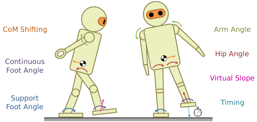
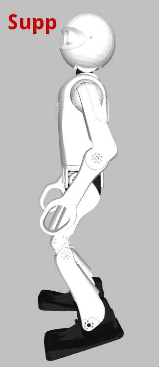
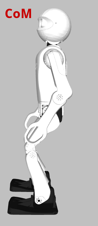
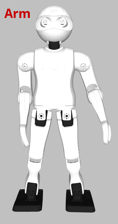
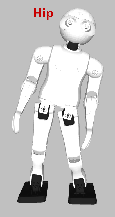
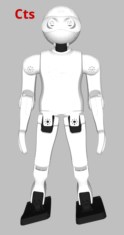
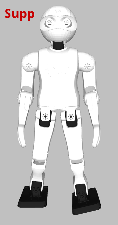
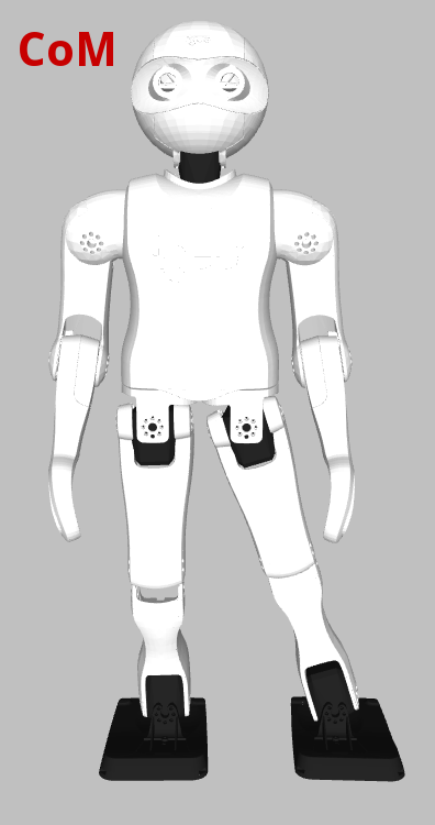
Feedback mechanisms have been implemented that apply direct additive corrective actions to the gait, based on the deviations of the fused pitch and fused roll from their nominal limit cycle values. The corrective actions can be thought of as motion primitives that are dynamically weighted and superimposed on top of the open-loop gait. The limit cycles of the fused angles are modelled as parametrised sine functions of the gait phase, and the fused angle deviations are defined as the difference between and their current expected values. Corrective actions in both the abstract space and inverse space (see Section III-B) have been implemented, namely (see Fig. 2):
-
•
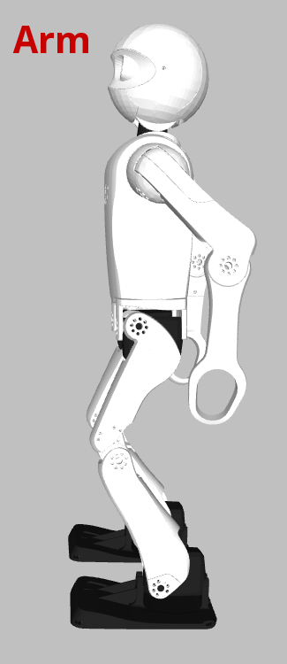
Arm angle: The abstract arm angles are adjusted to bias the robot’s balance, and produce reaction moments that help counterbalance transient instabilities (e.g. moving the arms backwards tilts the robot backwards).
-
•
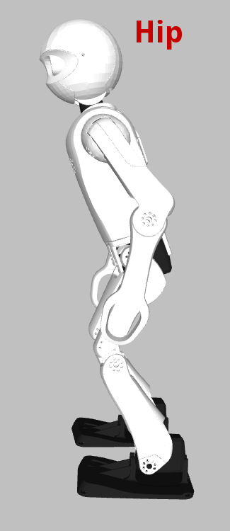
Hip angle: The torso of the robot is tilted within the lateral and sagittal planes to induce lean in a particular direction, with adjustment of the abstract leg extension parameters preventing a counterproductive ensuing difference in foot height (e.g. leaning towards the left makes the robot swing out more to the left).
-
•
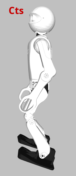
Continuous foot angle: Continuous offsets are applied to the abstract foot angles to bias the tilt of the entire robot from the feet up (e.g. putting the front of the feet more down makes the robot lean more backwards).
-
•
Support foot angle: Gait phase-dependent offsets are applied to the abstract foot angles (e.g. tilting the inside support foot edge down induces greater centre of mass swing onto the support foot). The offsets are faded in linearly just after the corresponding leg is extended fully, and faded out linearly just before the leg begins to retract again for its swing phase. As such, the offsets are applied only during the respective expected support phases, and at no point simultaneously.
-
•
CoM shifting: The inverse kinematic positions of the feet relative to the torso are adjusted in the horizontal plane to shift the position of the centre of mass (CoM), thereby adjusting the centering of the robot’s mass above its support polygon (e.g. shifting the CoM to the right trims the time spent on each foot to the right).
-
•
Virtual slope: The inverse kinematic positions of the feet relative to the torso are adjusted in the vertical direction in a gait phase-dependent manner to lift the feet more at one swing extremity. This can be thought of as what the robot would need to do to walk up or down a slope. See Section V-E for details.
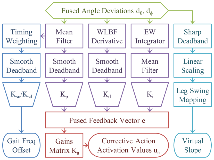
The complete feedback pipeline, from the fused angle deviations through to the resulting timing and corrective actions, is shown in Fig. 4. The various feedback mechanisms, including the calculation of the fused feedback vector
| (8) |
are discussed in the following sections. Once has been calculated, it is converted to a vector of corrective action activation values via premultiplication by a corrective action gains matrix . That is,
| (9) |
Note that a single gains matrix is used for generality and mathematical brevity, but in practice a full tune involves only 10-14 non-zero gains in the matrix. These intended feedback paths are explicitly stated in the following sections. The entries of give the magnitude and sign with which each of the available corrective actions—excluding the virtual slope, which is calculated and added separately (see Section V-E)—are applied to the abstract and inverse poses generated by the gait. This is how the robot acts to keep its balance.
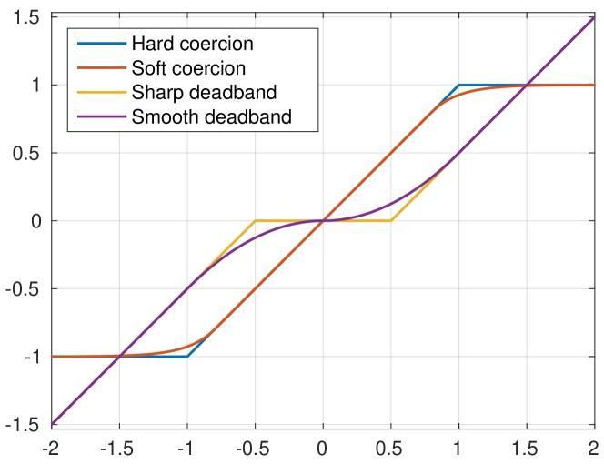
To ensure that the pose of the robot stays within suitable joint limits, smooth saturation is applied to the final abstract arm angles, leg angles, foot angles, and inverse kinematic adjustments to the CoM. Smooth saturation, also referred to as soft coercion, of a value to the range with a buffer of , is given by
| (10) |
The soft coercion transfer function is shown in Fig. 3. Soft coercion is used instead of the standard coercion , which simply saturates to the interval in a binary manner, because soft coercion is continuously differentiable (class ), resulting in smoother saturation behaviour and less self-disturbances of the robot.
V-A Fused Angle Deviation Proportional Feedback
The most fundamental and direct form of fused angle feedback is the proportional corrective action feedback. As with nearly all of the implemented feedback mechanisms, the proportional feedback operates in both the lateral and sagittal planes. The fused angle deviation values are first passed through a mean filter to mitigate the effects of noise. Smooth deadband is then applied to the output to inhibit corrective actions when the robot is close to its intended trajectory, to avoid oscillations due to hunting. Smooth deadband (see Fig. 3) is a adaptation of the standard ‘sharp’ deadband, and for input and deadband radius is given by
| (11) |
Smooth deadband was chosen for this application to soften the transitions between action and inaction, and to avoid any unnecessary self-disturbances and/or unexpected oscillatory activation-deactivation cycles, which can occur due to the strongly asymmetrical behaviour of sharp deadband around its threshold points. The proportional fused angle feedback values and from (8) are calculated by scaling the results of the smooth deadband by the proportional fused angle deviation gain . The proportional fused angle feedback mechanism is intended for activating the arm angle, support foot angle, and hip angle corrective actions.
V-B Fused Angle Deviation Derivative Feedback
The proportional feedback works well in preventing falls when the robot is disturbed, but if used alone has the tendency to produce possibly unstable low frequency oscillations in the robot. To enhance the transient disturbance rejection performance of the robot, corresponding derivative feedback terms are incorporated to add damping to the system. If the robot has a non-zero angular velocity, this component of the feedback reacts ‘earlier’ to cancel out the velocity before a large fused angle deviation ensues, and the proportional feedback has to combat the disturbance instead.
The derivative fused angle feedback values and are computed by passing the fused angle deviations and through a weighted line of best fit (WLBF) derivative filter, applying smooth deadband, and then scaling the results by the derivative fused angle deviation gain . The smooth deadband, like for the proportional case, is to ensure that no corrective actions are taken if the robot is within a certain threshold of its normal walking limit cycle, and ensures that the transition from inaction to action and back is smooth.
A weighted line of best fit (WLBF) filter observes the last data points of a signal, in addition to assigning confidence weights to each of the data points, and performs weighted linear least squares regression to fit a line to the data, with the data measurement timestamps being used as the independent variable. The linear fit evaluated at the current time gives a smoothed data estimate, and the fitted linear slope gives a smoothed estimate of the derivative of the data stream. WLBF derivative filters have a number of advantages, in particular when compared to the alternative of computing the numerical derivative of a signal, and applying a low pass filter. WLBF filters are more robust to high frequency noise and outliers in the data for the same level of responsiveness to input transients, and have the advantage of inherently and easily supporting non-constant time separations between data points in a stable manner, even if two data points are very close in time. The use of weights in WLBF filters also allows some data points to be given higher confidences than others in a probabilistic manner. For example, in regular parts of the gait cycle where noise and errors in the measurements are expected, lower weights can be used to help reject noise and disturbances in the sensor measurements. To the knowledge of the authors, the use of weighted linear least squares regression in this online fashion for the purposes of data smoothing and derivative estimation, in particular in the context of walking gaits, has not previously been published, so no references can be provided.
The derivative fused angle feedback values and , are intended for activating the arm angle, support foot angle and hip angle corrective actions, and serve to allow better loop shaping for the transient response to disturbances.
V-C Fused Angle Deviation Integral Feedback
The proportional and derivative fused angle feedback mechanisms are able to produce significant improvements in walking stability, but situations may arise where continued corrective actions are required to stabilise the robot, due to for example asymmetries in the robot. The continual control effort, and resulting periodic steady state errors, are undesired. The purpose of the integral feedback is to slowly converge on offsets to the gait halt pose that minimise the need for control effort during general walking.
The fused angle deviations and are first integrated over time using an exponentially weighted (EW) integrator, a type of ‘leaky integrator’. This computes the sum
| (12) |
where is the history time constant. The sum is most conveniently computed using the difference equation
| (13) |
If , the integrator simply returns the last data value, but if the output is the same as that of a classical integrator, so the value of effectively trims the amount of memory that the integrator has. A suitable value for is computed from the desired half-life time , which is a measure of the decay time of the integrator, using
| (14) |
where is the nominal time step. An EW integrator is used instead of a standard integrator for flexibility and stability reasons, to combat integrator windup, and because old data eventually needs to be ‘forgotten’ while walking, because situations can change. The alternative of keeping the last fused angle deviations in a buffer, and integrating over the buffer, is less efficient, less continuous in the output and less flexible, in addition to being vulnerable to aliasing effects.
The outputs of the two fused angle deviation EW integrators are passed through mean filters, to allow the trade-off between settling time and level of noise rejection to be trimmed, and scaled by the integral fused angle deviation gain to give the integral fused angle feedback values and . The integral fused angle deviation feedback is intended for activating a mix of the arm angle, continuous foot angle, hip angle, and CoM shifting corrective actions, although to preserve greater independence between the feedback mechanisms, primarily the last of these four is used.
V-D Fused Angle Deviation Timing Feedback
The PID feedback mechanisms act to return the robot to the expected fused angle limit cycles during walking. For larger disturbances this is not always possible, practicable and/or desired. For instance, if a robot is pushed so far laterally that it is only resting on the outer edge of its support foot, then no matter what fused angle feedback mechanisms are applied, it is infeasible to return the robot to its centred and upright position in the same time as during normal walking. This generally results in the robot attempting to make its next step anyway, and falling. To deal with this mode of failure, timing feedback has been implemented. This form of feedback adjusts the rate of progression of the gait phase as a function of the fused roll deviation . Steps taken by the robot can thereby be sped up or delayed based on the lateral balance state of the robot.
As the required sign of the timing feedback depends on the current support leg, and as only minimal timing adjustments are desired during the double support phase due to the fused angle noise associated with foot strike and weight shifting, the mean filtered fused roll deviation is first weighted by a saturated oscillatory gait phase-dependent expression:
| (15) |
where is the gait phase, is the double support phase length, and is a gain that adjusts the shape of the oscillatory weighting curve. To avoid unnecessary disturbances to the gait frequency during normal walking, smooth deadband is applied to the calculated weighted deviation to give the fused angle timing feedback value . The desired gait frequency is then
| (16) | ||||
| (17) |
where is the nominal gait frequency, is the maximum allowed gait frequency, and and are the speed-up and slow-down gains. Equation (7) is then used as normal to update the gait phase .
V-E Virtual Slope Walking
It can happen that a foot prematurely strikes the ground during its swing phase if the robot is tilted sagittally in the direction that it is walking. This is undesirable, and is a cause for destabilisation of the robot. Virtual slope walking adjusts the inverse kinematic height of the feet in a gait phase-dependent manner, based on the commanded gait velocity and the estimated attitude, to simulate the robot walking up or down a slope. For example, if the robot is walking forwards and tilted forwards, the robot lifts its feet higher at the front of its swing phases, ensuring that the legs still reach full forward swing before establishing ground contact.
The required sagittal virtual slope at each point in time is calculated as the fused pitch deviation with sharp deadband applied, and asymmetrically linearly scaled based on whether the robot is tilted in the direction it is walking or not. The virtual slope is then scaled by the sagittal gait command velocity , and applied to the inverse kinematic foot height as a linear function of the corresponding current sagittal leg swing angle.
VI Tuning of the Feedback Parameters
The process of tuning the feedback parameters is greatly simplified by the considerable independence of the feedback mechanisms. The individual feedback mechanisms also have clearly observable and direct actions that can be precisely isolated and tested, so arguably the process of tuning the proposed gait is quicker and easier than it would be for most model-based approaches that do not work out of the box.
The PD gains are tuned first, to establish the set of most effective corrective actions, and the gain ranges that produce noticeable effect without risking oscillations or instabilities. The choice of corrective actions may be influenced by external objectives, such as for example the desire to minimise trunk angle deviations from upright. In this case, the hip angle actions may for example be omitted. The transient sagittal response to disturbances comes predominantly from the PD feedback mechanisms, and can be tuned using an LQR-based approach. The robot is made to walk on the spot while activating the corrective actions with a multi-frequency signal, in a ratio chosen based on the relative desired ranges of the corrective actions. In the case of the igus® Humanoid Open Platform, the System Identification Toolbox in MATLAB was used to fit a generic second order state space system to the observed data, giving a model of
| (18) | ||||||
| (19) | ||||||
| (20) |
where the input is the activation of the corrective actions and the output is the fused pitch deviation. Cross-validation of the model was performed on two further data sets. The model has one fast pole (), attributed to the immediate conservation of momentum effect of moving the arms, and one slower pole (), which is approximately equal to the nominal gait frequency, and thus attributed to the gait and stepping dynamics. Similar to the approach in [16], the PD feedback law is given by
| (21) | ||||
| (22) |
A standard LQR design approach is then used to compute the gains vector that minimises the performance cost function
| (23) |
The and matrices were initially chosen based on Bryson’s rule [17] and subsequently refined. The maximum desired values of and for use with the rule were determined based on the simulated response of the model to the three data sets. Once has been calculated, the optimal PD gains, by inversion of (22), are then
| (24) |
Due to modelling limitations, the final gains that arise will usually require some manual fine-tuning to get the most out of the feedback, often an increase in the D gain. Locally around upright the sagittal dynamics are somewhat stable, so the LQR naturally assumes this also holds at greater trunk attitudes, but this is not correct.
Once the transient response has been tuned, a suitable integral feedback half-life is chosen based on the rate at which the robot should adapt to a new environment, and gains are chosen that brings the activation of the associated integral corrective actions to the desired range. Timing is then considered, with the speed-up and slow-down gains being selected to avoid premature stepping, and to instantaneously halt the gait phase when the robot reaches a certain nominal lateral angular deviation. The virtual slope mechanism is mostly parameter-free, and the sole linear scaling factor is chosen to provide the desired margin of clearance of the foot from the ground during maximum forwards walking.
VII Experimental Results
The proposed gait has been implemented and evaluated experimentally on four igus® Humanoid Open Platform robots [18], and for cross-validation also on the humanoid robot Dynaped. The latter is dynamically quite different from the igus robots, but was able to use essentially the same gains matrix . This demonstrates a strength of the gait, in that it is model-free and thereby relatively easy to transfer between robots. Overall, the feedback mechanisms were observed to make a significant difference in the walking ability of the tested robots, with walking often not even being possible for extended periods of time without them. The feedback mechanisms also imparted the robots with disturbance rejection capabilities that were not present otherwise. Reliable omnidirectional walking speeds of were achieved on an artificial grass surface of blade length .
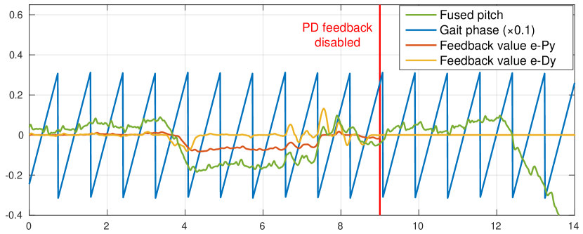
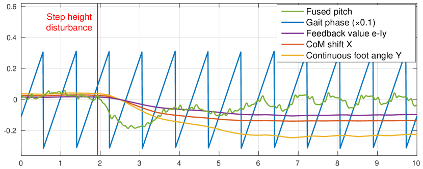
Plots of experimental results demonstrating the efficacy of the feedback mechanisms are shown in Fig. 5. In Fig. 5, the robot walked twice onto an unexpected step change in floor height, the first time with proportional and derivative feedback enabled, and the second time with them disabled. It can be seen that with the feedback enabled the robot is able to avoid falling—albeit with a large steady state error in the fused pitch—while without feedback the robot falls immediately. Adding in integral feedback, configured to activate both the CoM shift and continuous foot angle corrective actions, produces the results in Fig. 5. It can be seen that the relatively large error in the fused pitch is rejected in about , with the robot converging to upright walking despite the uneven floor. Note that the residual fused pitch limit cycles are an effect of the robot’s feet not being equally positioned on the step.
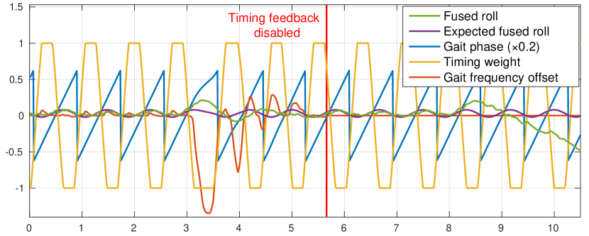
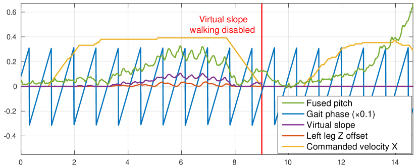
Fig. 5 shows the effect of the timing feedback. The robot was subjected to two lateral pushes while walking in place, the first with timing feedback enabled, and the second without. It can be seen at that the gait phase slows down in response to the push, allowing the fused roll to return to its expected limit cycle within . An identical push at , without timing feedback enabled, causes the robot to fall. Fig. 5 illustrates the effect of virtual slope walking. The robot was continuously pushed forwards while it was walking forwards, first with the virtual slope walking enabled, and then without. In the first case, the adjustments to the inverse kinematic height of the feet ensured that the robot could continue to walk forwards, and regain balance once it was no longer being pushed. In the latter case however, the feet started to collide with the ground in front of the robot. The robot was not able to get its feet underneath its CoM again, and subsequently fell shortly after.
The gait presented in this paper has successfully been run in combination with the capture step framework proposed in [9], and produced results notably superior to just using the latter on the igus® Humanoid Open Platform. The capture step timing was used in place of the fused angle deviation timing, and the step sizes computed from the capture step algorithm were used, but otherwise the full fused angle feedback mechanisms were running. The gait was used in this configuration at the RoboCup 2016 soccer tournament, and over all games played, none of the five robots ever fell while walking111Video: https://www.youtube.com/watch?v=G9llFqAwI-8, excluding cases of strong collisions with other robots. This validates the use of the presented gait as a stabilising foundation for more complex balancing schemes.
VIII Conclusion
An inherently robust omnidirectional closed-loop gait has been presented that stabilises a central pattern generated open-loop gait using fused angle feedback mechanisms. The gait is simple, model-free, quick to tune, easily transferable between robots, and only requires servo position feedback if feed-forward torque compensation is desired. The gait is also suitable for larger robots with low-cost sensors and position-controlled actuators. This demonstrates that walking does not always mandate complex stabilisation mechanisms. The gait has been experimentally verified and discussed, and demonstrably made a robot walk that was not able to produce nearly similar results with just a manually tuned open-loop approach. One of the notable merits of the presented gait is that it can combine very well with more complicated model-based approaches that are able to suggest step size and/or timing adjustments. This is what makes the gait so useful and powerful as a building block for more complex and more tailored gait stabilisation schemes.
References
- [1] K. Harada, S. Kajita, K. Kaneko, and H. Hirukawa, “An analytical method on real-time gait planning for a humanoid robot,” in Int. Conf. on Humanoid Robots (Humanoids), 2004.
- [2] M. Morisawa, K. Harada, S. Kajita, S. Nakaoka, K. Fujiwara, F. Kanehiro, K. Kaneko, and H. Hirukawa, “Experimentation of humanoid walking allowing immediate modification of foot place based on analytical solution,” in Int. Conf. on Robotics and Automation, 2007.
- [3] S. Kajita, F. Kanehiro, K. Kaneko, K. Fujiwara, K. Harada, K. Yokoi, and H. Hirukawa, “Biped walking pattern generation by using preview control of zero-moment point,” in IEEE Int. Conf. on Robotics and Automation (ICRA), 2003.
- [4] R. Tedrake, S. Kuindersma, R. Deits, and K. Miura, “A closed-form solution for real-time ZMP gait generation and feedback stabilization,” in Int. Conf. on Humanoid Robots (Humanoids), Seoul, Korea, 2015.
- [5] P.-B. Wieber, “Trajectory free linear model predictive control for stable walking in the presence of strong perturbations,” in IEEE Int. Conf. on Humanoid Robots (Humanoids), 2006.
- [6] M. Morisawa, F. Kanehiro, K. Kaneko, N. Mansard, J. Sola, K. Yokoi, E. Yoshida, and J. Laumond, “Combining suppression of the disturbance and reactive stepping for recovering balance,” in IEEE Conf. on Intelligent Robots and Systems (IROS), 2010.
- [7] P. Kryczka, P. Kormushev, N. Tsagarakis, and D. Caldwell, “Online regeneration of bipedal walking gait optimizing footstep placement and timing,” in Int. Conf. on Intell. Robots and Systems (IROS), 2015.
- [8] J. Urata, K. Nshiwaki, Y. Nakanishi, K. Okada, S. Kagami, and M. Inaba, “Online decision of foot placement using singular LQ preview regulation,” in IEEE Int. Conf. on Humanoid Robots, 2011.
- [9] M. Missura, “Analytic and learned footstep control for robust bipedal walking,” Ph.D. dissertation, University of Bonn, 2015.
- [10] M. Missura and S. Behnke, “Self-stable omnidirectional walking with compliant joints,” in Proceedings of 8th Workshop on Humanoid Soccer Robots, Int. Conf. on Humanoid Robots, 2013.
- [11] M. Schwarz and S. Behnke, “Compliant robot behavior using servo actuator models identified by iterative learning control,” in Proceedings of 17th RoboCup Int. Symposium, Eindhoven, Netherlands, 2013.
- [12] B. Armstrong-Hélouvry, Control of Machines with Friction, ser. The Springer International Series in Engineering and Computer Science. Springer US, 1991, vol. 128.
- [13] S. Behnke, “Online trajectory generation for omnidirectional biped walking,” in Proceedings of 2006 IEEE International Conference on Robotics and Automation, Orlando, USA, 2006.
- [14] P. Allgeuer and S. Behnke, “Robust sensor fusion for biped robot attitude estimation,” in Proceedings of 14th IEEE-RAS Int. Conference on Humanoid Robotics (Humanoids), Madrid, Spain, 2014.
- [15] P. Allgeuer and S. Behnke, “Fused Angles: A representation of body orientation for balance,” in Int. Conf. on Intelligent Robots and Systems (IROS), Hamburg, Germany, 2015.
- [16] S. Mukhopadhyay, “P.I.D. equivalent of optimal regulator,” Electronics Letters, vol. 11, no. 16, 1978.
- [17] G. Franklin, D. Powell, and A. Emami-Naeini, Feedback Control of Dynamic Systems, 7th ed. Boston Pearson, 2015.
- [18] P. Allgeuer, H. Farazi, M. Schreiber, and S. Behnke, “Child-sized 3D Printed igus Humanoid Open Platform,” in Proceedings of 15th IEEE-RAS Int. Conf. on Humanoid Robots (Humanoids), Seoul, Korea, 2015.