On the Impact of Spillover Losses in 28 GHz Rotman Lens Arrays for 5G Applications
Abstract
This work demonstrates the sensitivity of lens antenna arrays operating at millimeter-wave (mmWave) frequencies. Considering a Rotman lens array in receive mode, our investigation focuses on its most imperative defect: aberration of electromagnetic (EM) energy. Aberration leads to spillover of electric fields to neighboring ports, reducing the lens’ ability to focus the EM energy to a desired port. With full EM simulations, we design a 28 GHz, 13 beam and 13 array port Rotman lens array to characterize its performance with the aforementioned impairment. Our findings show that the impact of aberration is more pronounced when the beam angles are close to the array end-fire. More critically, the corresponding impact of aberration on the desired signal and interference powers is also investigated for an uplink multiuser cellular system operating at 28 GHz. The presented results can be used as a reference to re-calibrate our expectations for Rotman lens arrays at mmWave frequencies.
I Introduction
Radio-frequency (RF) lens-enabled antenna arrays have considerable potential to reduce the hardware complexity at millimeter-wave (mmWave) frequencies [1]. ††This work was supported by the EPSRC, UK, under grant EP/P000673/1 and EP/EN02039/1. Nevertheless, lens arrays suffer from the inherent quantization of the beamspace. In addition, errors due to imperfections in the lens construction itself have a critical impact on its performance. Almost all of the existing studies on lens-based architectures as a radio transmitter or receiver consider the lens as an ideal (perfect) RF device (see e.g., [1, 2, 3, 4] and references therein). A common topology in the literature is known as the Rotman lens, which is designed with three focal points where lens operation is perfect. At all other focal points, lens aberration occurs [5], causing spillover losses - as electromagnetic (EM) energy which may be desired for a particular beam port also leaks into neighboring beam ports. This counteracts the functionality of the lens, causing high levels of desired signal loss. The impact of this physical artifact on the overall system performance remains uncharacterized in the literature, and in this paper, we close this gap. More specifically, with a Rotman lens antenna array at 28 GHz, we investigate the impact of aberration on an uplink multiuser cellular system operating with analog and baseband processing. In doing so, via EM simulations, we characterize the inherent limitations of Rotman lens arrays by studying the spillover levels as a function of the azimuth direction-of-arrivals (DoAs).
II Design Principles of Rotman Lens Arrays
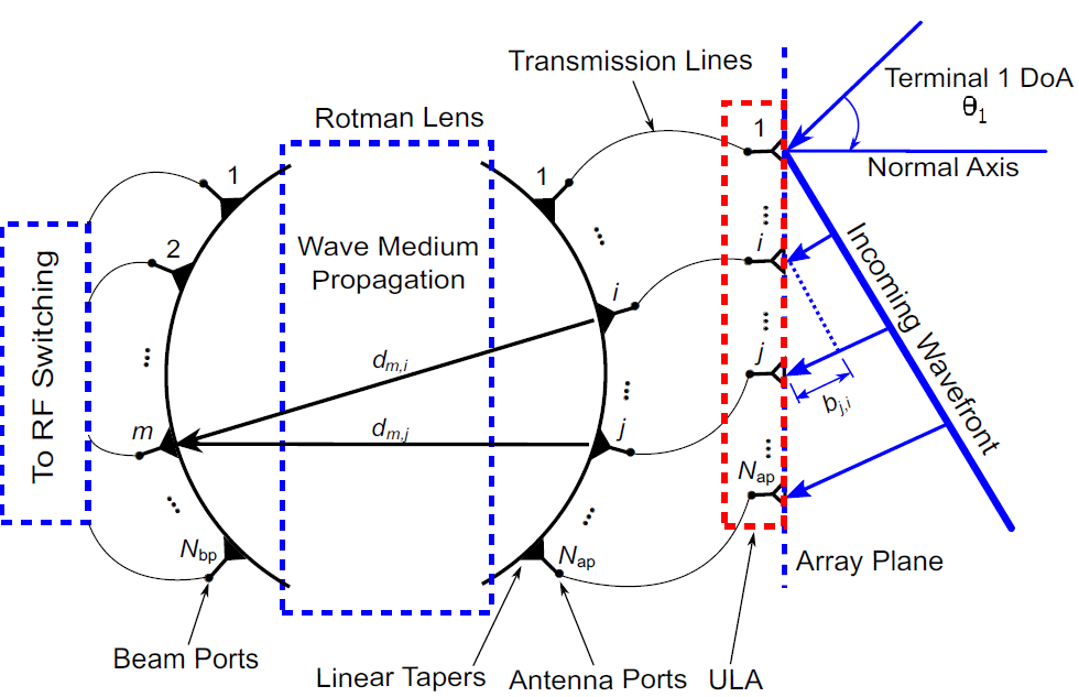
Successful operation of mmWave cellular systems will requires pencil-like beam-steering capability in order to accurately steer/receive the transmit/receive gain towards/from the strongest scatterer(s) in the far-field propagation channel. Most commonly, this is done via a network of analog phase shifters interfaced with the array elements (see e.g., [6]). However, it is well known that mmWave phase shifters tend to be significantly lossy, and often incapable of providing precise phase shifts over the required system bandwidth. More accurate phase shifters based on tunable materials often need to be driven by an external control signal, leading to higher circuit complexity and material cost [7]. Rotman lenses provide an attractive alternative to phase shifter networks, which are increasingly considered [1, 3, 2, 4]. A Rotman lens provides switch-less multi-beam operation of an antenna array with a wide beam-steering range. Figure 1 presents the generalized schematic diagram of a Rotman lens with beam-ports and array ports, all connected to the corresponding tapering and transmission lines. The area annotated as wave medium propagation is where wave superposition takes place. The tapering and transmissions lines are normally used to artificially introduce time delays such that the waves propagating through the transmission lines are phase aligned along the port terminations. A separate set of ports generally referred to as the dummy ports, are introduced to increase the adjacent beam port isolation. The dummy ports are normally terminated in a matched load, and thus result in minimizing the reflections from the side walls of the lens. The beam side and array side curvature is defined using design parameters: on-axis focal length , off-axis focal length , their ratio , the focal angle , the sweep angle , and the lens expansion factor defined as . A detailed description of the above parameters can be found in [8]. While realizing a specific Rotman lens geometry, the aforementioned parameters define a convex polygon, where the beam and the array port focal points can be identified [8]. The part of the lens around these points is usually referred to as the port segment, and is connected to tapered lines which guide the propagating wave towards corresponding transmission line.
III 28 GHz Electromagnetic Design
of a Rotman Lens Array
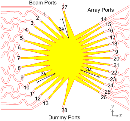
Here we present the design of a 28 GHz Rotman lens constructed on a 0.64 mm thick Taconic-RF 60 substrate ( using microstrip technology. In our design, , and two dummy ports are considered. The lens’s parallel plate region was synthesized by the design parameters of a tri-focal Rotman lens model [3, 8]. The predefined design parameters were , , , , and the array steering angle was set to . The tapering lines for all the ports are in length. Moreover, the Finite-Difference-Time-Domain (FDTD) method was used to characterize the lens in full-wave electromagnetic (EM) simulation. The physical lens geometry is presented in Fig. 2 with port numbering defined in the caption. Although this specific example was constructed using standard synthesis method, it is important to mention that with a careful selection of the design parameter of the parallel plate region, the lens performance can be advanced to an extent. Further to this, it is worth mentioning that the geometrical parameters of the overall Rotman geometry (parallel plate region, dummy ports, tapered transitions and transmission lines) can be optimized to further improve the lens performance [3].
IV Results and Discussion
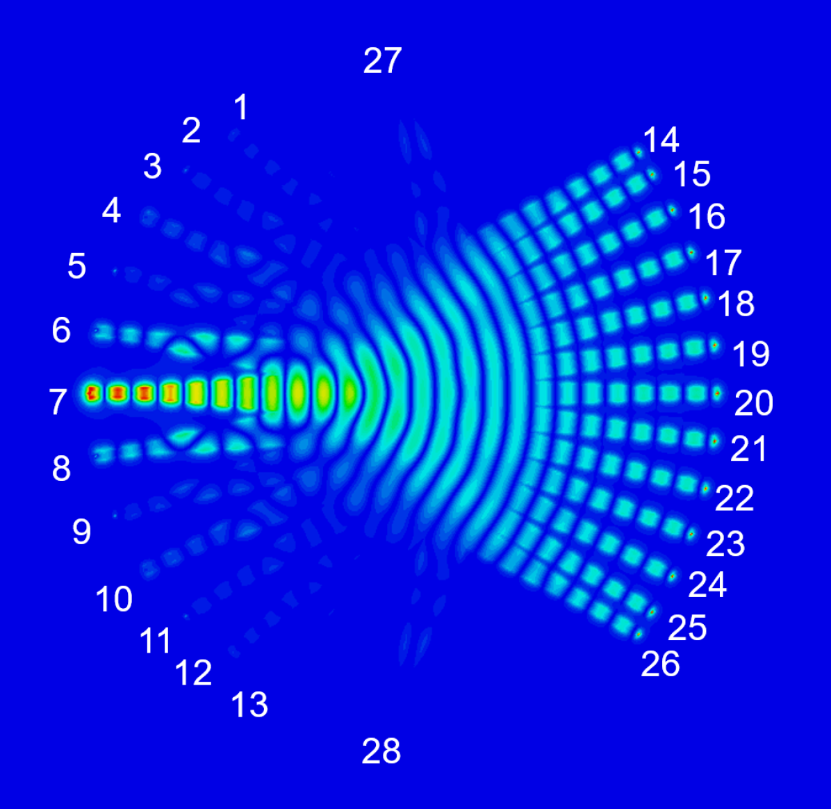
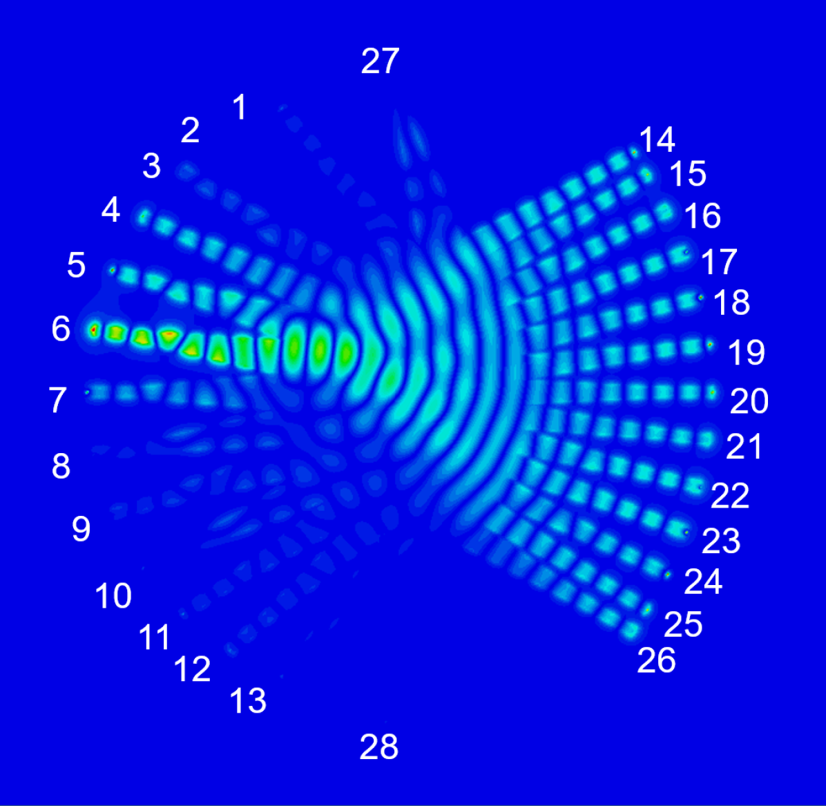
A set of EM simulations were carried out in which array ports of the lens were excited by phase ramped power signals representing multiple DoAs along the azimuth plane. For the sake of brevity, only three distinct scenarios are presented in Fig. 3. In the first case (denoted by DoA1), the beam is propagating in a line-of-sight (LOS) manner from a potential transmitting source which could be located at relative to the antenna array (see Fig. 1). Based on the electric field distributions shown in Fig. 3 (a), it is evident that the maximum power is converged at the central beam port, i.e., port 7, while a small portion of the power is spilled over to the neighboring ports due to aberration. One can also notice from Figs. 3 (b) and (c), that the amount of spillover increases as is varied from (DoA 2) to (DoA 3). One can also observe the reflection in addition to spillover towards the opposite ports (9 - 12) in case of DoA 3; a trend which is not significant at broadside-like angles. Note that the DoA 2 and DoA 3 cases do not coincide with any of the designed focal points of the Rotman lens array, and hence are purely demonstrating the spillover effects on the Rotman lens focusing. This result highlights one of the major limitations of the Rotman lens, and demonstrates the fact that the EM focusing is more accurate towards the broadside excitation angles.

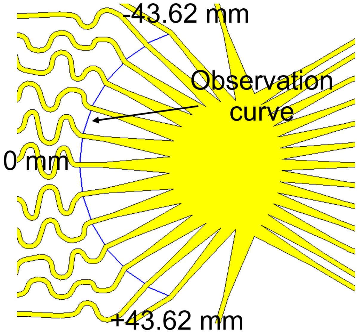
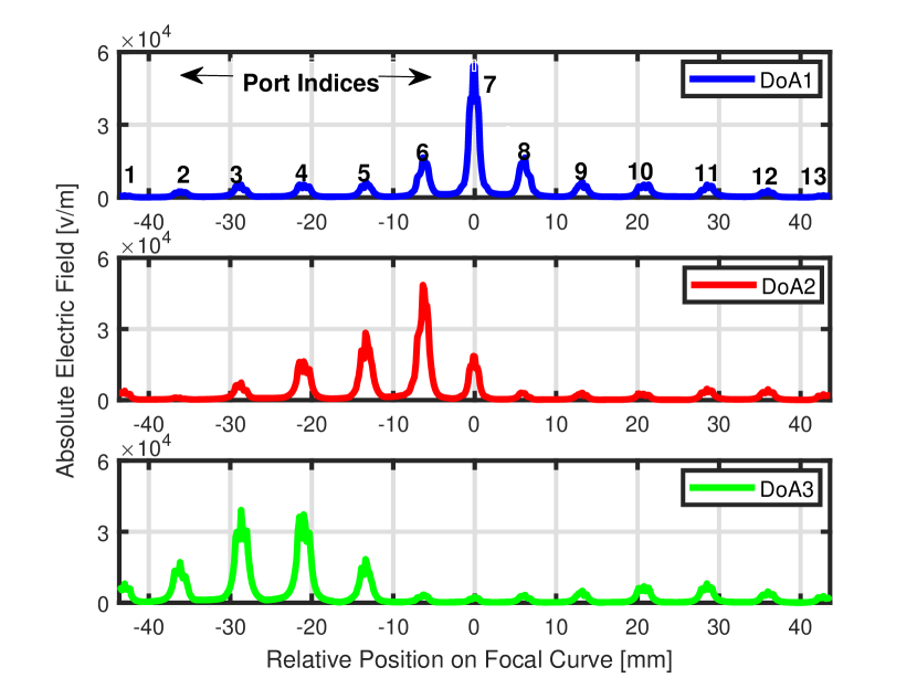
To quantify the field leakage into the neighboring ports of the lens, we show an observation curve m inside the Taconic substrate layer (see Fig. 4 (a)). The one-dimensional plot of electric field as a function of the Rotman curve length for all DoA cases is presented in Fig. 4 (b). The field maxima along the curve length are indicative of 13 ports. It is interesting to note that the field distribution for DoA1 is fairly symmetric. This is unlike DoA2, which reveals a contour with an uneven distribution of fields, one where the spillover profile is vastly different for the central and the edge ports. The final case in Fig. 4 (b) the contour for DoA3, where the wave converging point falls at the boundary of two ports. Catastrophically, the power is distributed between two concurrent ports almost equally. Here the effects of RF reflections can also be observed in addition to the spillover, where peaks in the contour profile are observed between 20-40 mm.
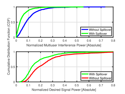
In order for one to understand the ultimate impact of aberration, we simulate an uplink multiuser MIMO system, where two mobile terminals simultaneously transmit uplink data to a Rotman lens-enabled array. Upon receiving the signals, the Rotman array is fed with a network of RF switches, followed by two complete down-conversion chains to recover the transmitted data at baseband. We employ the use of maximum-ratio (MR) baseband combining to separate the multiple arriving streams. The 28 GHz far-field propagation channel is simulated following the classical double-directional description [9]. Precisely, we consider the total number of scattering clusters in the propagation channel to be 4, with each cluster contributing the total of 5 sub-paths. The instantaneous path gains are assumed to be Gaussian distributed with zero-mean and unit variance. The far-field array steering vector of a linear array is utilized with a uniform beam scanning range in the forward half space of the array (). Large-scale fading (geometric attenuation and shadow fading/blockage) is modeled on both links using the classical power loss model described in [2]. Due to space constraints, we avoid presenting further information regarding the simulation setup, as well as the exact mathematical descriptions of the desired signal and interference powers with MR processing. These can be found in [2]. Figure 5 depicts the desired signal and multiuser interference power cumulative distribution functions (CDFs) with and without aberration, at an operating SNR of 0 dB. One can observe that with aberration, there is naturally a loss in the desired signal power, more pronounced at probability values around 0.5. This is due to the leakage of the desired EM energy to the neighboring ports, allowing the power to spread out. In stark contrast, a reduction in the interference power is observed with aberration. This is due to the fact that the spreading of the EM energy across multiple ports effectively helps to de-correlated the uplink signals in the RF domain, such that the interference power is not concentrated on a particular port, but rather distributed to a set of ports. It is worth noting that overall, it is the ratio of the desired signal to the interference power which is seen at a user terminal. The dominance of one over the other is a function of all involved system parameters, as well as aberration levels. Hence, in order not to obfuscate the findings, we avoid discussing the ratio explicitly.
V Conclusions
We present an investigation into the spillover losses of a 28 GHz Rotman lens array. Via the aid of full EM simulations, for a 1313 Rotman array, we conclude that the impact of spillover is significantly more pronounced at beam angles closer to the array end-fire. More accuracy in the spatial focusing is found when the arriving beam at the Rotman array is around the broadside direction, corresponding to exciting the central ports. The impact of aberration on the desired signal and interference characteristics were investigated. To the best of the authors’ knowledge, such a type of investigation is missing from the lens literature.
References
- [1] A. M. Sayeed and J. Brady, “Beamspace MIMO channel modeling and measurement: Methodology and results at 28GHz,” in Proc. IEEE GLOBECOM (Workshops), Dec. 2016.
- [2] H. Tataria, et al., “Uplink interference analysis with RF switching for lens-based millimeter-wave systems," in Proc. IEEE ICC, May 2018.
- [3] Y. Gao, et al., “Rotman lens based hybrid analog-digital beamforming in massive MIMO systems: Array architectures, beam selection algorithms and experiments”, IEEE Trans. Veh. Technol., vol. 66, no. 10, pp. 9134-9148, Oct. 2017.
- [4] Y. Zeng and R. Zhang, “Millimeter wave MIMO with lens antenna array: A new path division multiplexing paradigm," IEEE Trans. Commun., vol. 64, no. 4, pp. 1557-1571, Apr. 2016.
- [5] M. Jiang, et al., “Metamaterial-based thin planar lens antenna for spatial beamforming and multibeam massive MIMO,” IEEE Trans. Antennas Propag., vol. 65, no. 2, pp. 464-472, Feb. 2017.
- [6] W. Roh, et al., “Millimeter-wave beamforming as an enabling technology for 5G cellular communications: Theoretical feasibility and prototype results," IEEE Commun. Mag., vol. 52, no. 2, pp. 106-113, Feb. 2014.
- [7] R. Mendez-Rial, et al., “Hybrid MIMO architectures for millimeter wave communications: Phase shifters or switches?," IEEE Access, vol. 4, pp. 247-267, Jan. 2016.
- [8] R. C. Hansen, “Design trades for Rotman lenses," IEEE Trans. Antennas Propag., vol. 39, no. 4, pp. 464-472, 1991.
- [9] M. Steinbauer, et al., "The double-directional radio channel," in IEEE Antennas and Propag. Mag., vol. 43, no. 4, pp. 51-63, Aug 2001.