Polarized laser-wakefield-accelerated kiloampere electron beams
Abstract
High-flux polarized particle beams are of critical importance for the investigation of spin-dependent processes, such as in searches of physics beyond the Standard Model, as well as for scrutinizing the structure of solids and surfaces in material science. Here we demonstrate that kiloampere polarized electron beams can be produced via laser-wakefield acceleration from a gas target. A simple theoretical model for determining the electron beam polarization is presented and supported with self-consistent three-dimensional particle-in-cell simulations that incorporate the spin dynamics. By appropriately choosing the laser and gas parameters, we show that the depolarization of electrons induced by the laser-wakefield-acceleration process can be as low as 10%. Compared to currently available sources of polarized electron beams, the flux is increased by four orders of magnitude.
Polarized beams of electrons, photons and positrons are widely employed in materials science Schultz and Lynn (1988) as well as in atomic, nuclear and particle physics Tolhoek (1956); Danielson et al. (2015) because they allow the investigation both of the spin dependence of fundamental interactions and of the violation of symmetries such as parity Schlimme et al. (2013). In fact, precise measurements of spin-dependent processes enable searches of physics beyond the Standard Model that can compete with direct searches at high-energy accelerators D. Androic et al. (2018) (Qweak Collaboration). In addition to their intrinsic interest, polarized electron beams can also be employed to generate polarized beams of photons Märtin et al. (2012) and positrons Abbott et al. (2016) which, in turn, can be employed to address long-standing problems such as the matter-antimatter asymmetry in the Universe.
Currently, polarized electron beams are mainly produced in storage rings via radiative polarization due to the Sokolov-Ternov effect Sokolov and Ternov (1967) or by extracting polarized electrons Kessler (1985) directly from polarized atoms and polarized photocathodes Pierce et al. (1975). However, the maximal electric current of polarized electron beams both from storage rings Barber et al. (1993); Sun et al. (2010) and from photocathodes von Drachenfels et al. (2003); Maxson et al. (2014); Hernandez-Garcia et al. (2016) is limited to less than ampere due to their operational voltages. Other methods based on spin filters Batelaan et al. (1999), Stern-Gerlach-like beam splitters Dellweg and Müller (2017), and radiative polarization Li et al. (2019) also yield relatively low currents. The low attainable electric currents noticeably limit experiments with polarized beams Schultz and Lynn (1988); Tolhoek (1956); Danielson et al. (2015) as well as the flux and the brightness of the polarized photon and positron beams attainable from polarized electron beams Märtin et al. (2012); Abbott et al. (2016).
Here we put forward a method for generating polarized electron beams with currents four orders of magnitude larger than those attainable with currently existing methods. It consists in the rapid electron polarization of a gas jet via photodissociation by a circularly-polarized UV laser pulse followed by electron laser-wakefield acceleration by an optical laser pulse. An illustration of our scheme is displayed in Fig. 1. A tens femtoseconds linearly polarized optical laser pulse with hundreds mJ energy and low intensity is divided into two pulses with a beam splitter. One of the two pulses first passes through a grating pair, where it is stretched to hundreds picoseconds, and is further divided into two pulses with a second beam splitter. One picosecond pulse is used to initially align the molecular bonds before dissociation Friedrich and Herschbach (1995); Sofikitis et al. (2017); Hützen et al. (2019), the other one undergoes frequency quadruplication with a BBO and KBBF crystal, and its bandwidth is tightened via reflection with several narrow band coated mirrors [not displayed in Fig. 1(a)]. The generated UV laser pulse is converted to circular polarization with a quarter-wave plate and focused to the gas target where it polarizes electrons along the laser propagation direction via molecular photodissociation Rakitzis et al. (2003); Rakitzis (2004); Sofikitis et al. (2008, 2017, 2018); Hützen et al. (2019). Note that electronically polarized atomic hydrogen with density up to was already experimentally obtained by employing laser-induced molecular photodissociation Sofikitis et al. (2018). The second of the two pulses from the first beam splitter passes through a controllable delay line and reaches the previously generated electronically polarized gas target to drive wakefield acceleration [see Fig. 1(a)]. The delay between the polarizing UV laser pulse and the optical laser pulse driving wakefield acceleration must be much smaller than ns, i.e., the time needed to the hyperfine coupling to transfer polarization from electrons to nuclei Sofikitis et al. (2017). According to the shock-front injection method Buck et al. (2013), the electron density is tailored along the laser propagation direction [see Fig. 1(b)]. This allows to control the local plasma period (wavelength) [] along the laser propagation direction such that only the electrons in the downramp of the density, i.e. in the region between and of Fig. 1(b), are injected and accelerated into the wake wave Buck et al. (2013). Here is the vacuum permittivity, and are the electron mass and charge, respectively.
The initial electronic polarization (IEP) of the gas target depends on the employed molecular species. In particular, hydrogen halides were used to generate dense electronically polarized hydrogen and deuterium atoms Sofikitis et al. (2017, 2018). In this case, the presence of other species than hydrogen implies that, although the IEP of hydrogen can reach 100% Sofikitis et al. (2017), the global IEP of the generated plasma is less than unity. However, as it will be clear in the following, only optical laser pulses with intensity of the order of drive laser-wakefield acceleration without significant electron beam depolarization. Hence, for halogen atoms only the outer shell electrons have appreciable probability to be extracted and accelerated Clayton et al. (2010); Chen et al. (2013). By considering HF molecules, six paired electrons in the outer-shell of fluorine may be extracted and accelerated by the optical driver laser pulse, which results into an IEP . Higher IEP is expected by employing molecular hydrogen. However, single photon dissociation of molecular hydrogen occurs at wavelength Glass-Maujean et al. (1988), which has not yet been realized experimentally but may be attained via laser-plasma techniques Chen and Pukhov (2016).
In the following, we investigate electron injection and acceleration in the case of an initially fully electronically polarized plasma with spin directed along the driver laser propagation direction . In fact, a partially polarized gas is a mixture of a fully polarized fraction and of an unpolarized fraction Kessler (1985). Since the unpolarized fraction remains unpolarized, the final electron beam polarization (EBP) from a partially polarized gas is , where is the final EBP of an initially fully polarized plasma. Depolarization of an initially polarized target occurs due to the electromagnetic field inhomogeneities in the wake of the driving laser pulse. In particular, the spin of injected off-axis electrons precesses differently depending on the electron position, and mainly according to the structure of the azimuthal magnetic field in the wake wave Gorbunov et al. (1996, 1997); Andreev et al. (1997) [see Fig. 1(c)]. As it will be clear below, the IEP is preserved in the weakly-nonlinear wakefield acceleration regime Gorbunov and Kirsanov (1987); Esarey et al. (1997); Andreev et al. (1997); Marquès et al. (1998); Gorbunov et al. (2005); Kalmykov et al. (2006), with most of the injected electrons moving predominantly along the laser propagation direction and originating from the region near the laser propagation axis.
The electron beam dynamics is investigated with fully three-dimensional particle-in-cell (PIC) simulations with the code EPOCH Arber et al. (2015). In addition to the electron position and velocity , we implemented in the code the electron spin dynamics Wen et al. (2017). Following Ehrenfest’s theorem Ehrenfest (1927), a vector with is used to describe the spin of an electron in a quasiclassical state, where denotes the normalized two-component spinor and are the Pauli matrices Mane et al. (2005). In general, the EBP is defined as the statistical average over all electrons of the beam , where is the total number of electrons of the beam. The spin of an electron in an electric and magnetic field precesses according to the Thomas-Bargmann-Michel-Telegdi equation with
| (1a) | ||||
| (1b) | ||||
where is the anomalous magnetic moment of the electron. Note that electrostatic Coulomb collisions do not affect the electron spin, such that depolarization via collisions can only occur due to spin-orbit and spin-spin interaction Berestetskii et al. (1982); Kulsrud et al. (1982). Indeed, for spin polarized hydrogen density obtained from hydrogen halide molecular dissociation, a collisional polarization lifetime larger than 1 ns was demonstrated Sofikitis et al. (2018), which is much longer than the electron injection and acceleration time of approximately 1.1 ps considered here (see below). Also, Stern-Gerlach and radiation reaction forces are negligible at the low intensities and copropagating geometry considered here Wen et al. (2017); Tamburini et al. (2010).

In our PIC simulations we have chosen laser and plasma parameters similar to those already obtained in experiments with shock-front injection Schmid et al. (2010); Buck et al. (2013); Swanson et al. (2017); Xu et al. (2017). The plasma density profile is shown in Fig. 1(b). A density bump centered at with peak density is followed by a plateau beginning at and having uniform density , where is the critical plasma density, , , and are the laser wavelength, period, and frequency, respectively. At a laser pulse linearly polarized along the -axis and propagating along the positive -axis enters the simulation box from with focus located at . The laser pulse has Gaussian envelope , where , , is the normalized laser field amplitude, and is the maximal laser field. A moving window was employed, with computational box and grid points.
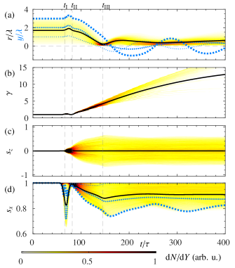
Figure 2 reports the evolution of the distribution of trapped electrons for a laser pulse with as a function of the radial coordinate [Fig. 2(a)], of the relativistic factor [Fig. 2(b)], of the [Fig. 2(c)] and [Fig. 2(d)] components of the electron spin . In addition, the dotted light-blue lines in Fig. 2 display the evolution of three electrons with initial coordinate . The evolution is divided into four stages. Stage I corresponds to , i.e. the time before the laser pulse peak reaches the injection volume, which is located near the maximum of the density bump . In fact, after the local plasma wavelength reaches its minimum , the density downramp leads to the expansion of the wake with a decrease of the wake phase velocity, which results into electron injection in the wakefield Buck et al. (2013). The injection region ends before the uniform density plasma at , i.e. when the local plasma wavelength reaches . In our simulations, we trace all and only the electrons that remain in the accelerating phase of the wake. The initial region of trapped electrons constitutes the injection volume with a radius Swanson et al. (2017).
Stage II begins at , where the electrons of the injection volume undergo a transient acceleration phase due both to the laser and to the wake-wave fields, as shown in Figs. 2(a)-(b). This transient phase lasts approximately one plasma period corresponding to the local density at , i.e. . During this stage the electrons of the injection volume move along the density downramp with mildly relativistic velocity. Note that at the laser pulse peak is at , i.e. well inside the uniform plasma that starts at , and that the oscillatory dynamics driven by the laser and the wake field tends to restore the initial momentum and spin of electrons (see Figs. 2(a)-(d) at ). Also, note that the linearly polarized laser pulse has its magnetic field directed along , such that it does not directly affect . Hence, the spreading of the distribution for is determined by the azimuthal magnetic field of the wake wave [see Figs. 2(c)].
Stage III starts at , where electron trapping with acceleration and focusing inside the wakefield occurs, as shown in Figs. 2(a)-(b). The simultaneous processes of acceleration and focusing become manifest in the decrease of the radius of the volume of the injected electrons [see Fig. 2(a)] and in the increase of the electron beam relativistic factor [see Fig. 2(b)], respectively. Here brackets denote the statistical average over the electrons of the injection volume. Simulations indicate that the focusing time, i.e. the time needed by the electrons of the injection volume to focus to the wake axis, is approximately , which implies that stage III ends at (see Fig. 2). Note that electron spin spreading occurs predominantly during stage III, i.e. between and , such that one can estimate the electron beam depolarization from the duration of stage III and from the spin precession frequency during this stage (see below).
During stage IV (), the energy of the electron beam increases steadily, whereas the spin distribution and beam polarization remain stable [see Fig. 2(c)-(d)]. Three factors determine the stability of the EBP during stage IV. First, the constantly increasing relativistic factor significantly reduces the precession frequency [see Eq. (1a)]. Second, our simulations show that for trapped electrons are predominantly focused and confined around the wakefield axis within a region of radius smaller than [see Fig. 2(a)]. This results into a suppressed precession frequency since transverse fields around the axis are relatively weak [see Eq. (2) below]. Third, trapped electrons oscillate around the axis of the wakefield while accelerated [see the dotted light-blue lines in Fig. 2(a)], which results into a change of the direction of at each crossing of the axis. Thus, oscillates around zero, while averages out to zero.
In order to evaluate the electron beam depolarization, we estimate the electron precession frequency during stage III. Recalling that and taking the limit of slowly varying frequency , at the end of stage III the component of the spin of an electron initially directed along the axis is . The precession frequency decreases steadily from its maximum at , where the injected electrons have and a relatively large , which implies a larger (see Eq. (2) below), to nearly zero at (see the black curve of Fig. 2(d) for ). For simplicity, in our analytical estimate we assume a linear decrease of from at to zero at for all the electrons of the injection volume, which implies . For , the quasistatic azimuthal magnetic field in the wake is Gorbunov et al. (1996, 1997):
| (2) |
where . Owing to the cylindrical symmetry of , the spin of electrons with symmetric trajectories with respect to the wakefield axis precess symmetrically but in opposite direction in the plane orthogonal to , as sketched in Fig. 1(c). This symmetric precession implies a symmetric spin spreading with [see Fig. 2(c)] together with a decrease of [see Fig. 2(d)]. The EBP is therefore obtained by integrating over the electrons of the cylindrical injection volume:
| (3) |
In order to carry our the integration in Eq. (3), an estimate of is needed. Our simulations indicate that, even though weakly depends on the laser intensity, the injection volume radius is roughly (see below).
Figure 3 displays the radial distribution of the injected electrons and the radius of the injection volume [Fig. 3(a)], the distribution and the EBP from PIC simulations (black circles) and from the analytical estimation with Eqs. (2)-(3) [light blue curve in Fig. 3(b)], the electric current carried by the beam [Fig. 3(c)], and the electron energy spectrum [Fig. 3(d)], where is the electron kinetic energy, at as functions of laser amplitude . In particular, Fig. 3(a) shows that the linear increase in the number of injected particles around the axis is followed by a sharp decrease of around the injection radius [see Fig. 3(a)]. Note that the number of electrons injected in the beam increases with increasing , which is also manifest in the increase of the electric current carried by the beam [see Fig. 3(c)]. However, the azimuthal magnetic field increases rapidly with [see Eq. (2)], such that an increase in results also into stronger depolarization [see Fig. 3(b)].
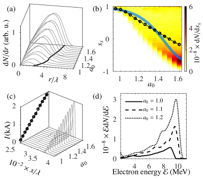
Figure 3 shows that in the weakly nonlinear wakefield regime electron beams carrying currents of the order of one kiloampere and retaining the IEP of the plasma can be produced. The final EBP and current from 3D PIC simulations with are and kA, respectively. The difference between the PIC simulation results and the prediction shown in Fig. 3(b) for is ascribed to the limited validity of Eq. (2) for significantly larger than unity Gorbunov et al. (1997). After the acceleration in the shock-front injector, which occurs within hundreds of micrometers Schmid et al. (2010); Buck et al. (2013); Swanson et al. (2017); Xu et al. (2017), the accelerator stage can be further extended to obtain GeV beams via multiacceleration-stage techniques powered by the same Kim et al. (2013) or different Steinke et al. (2016) laser pulses. In fact, further acceleration of already ultrarelativistic polarized electron beams weakly alters the EBP Vieira et al. (2011).
Acknowledgements.
We would like to thank M. Büscher and A. Di Piazza for the helpful discussions. M. W. thanks Y. Fu and C. Lin for their kind help and stimulating discussions about the plasma target and the laser system.References
- Schultz and Lynn (1988) P. J. Schultz and K. G. Lynn, “Interaction of positron beams with surfaces, thin films, and interfaces,” Rev. Mod. Phys. 60, 701–779 (1988).
- Tolhoek (1956) H. A. Tolhoek, “Electron polarization, theory and experiment,” Rev. Mod. Phys. 28, 277–298 (1956).
- Danielson et al. (2015) J. R. Danielson, D. H. E. Dubin, R. G. Greaves, and C. M. Surko, “Plasma and trap-based techniques for science with positrons,” Rev. Mod. Phys. 87, 247–306 (2015).
- Schlimme et al. (2013) B. S. Schlimme et al., “Measurement of the neutron electric to magnetic form factor ratio at using the reaction ,” Phys. Rev. Lett. 111, 132504 (2013).
- D. Androic et al. (2018) (Qweak Collaboration) D. Androic et al. (Qweak Collaboration), “Precision measurement of the weak charge of the proton,” Nature 557, 207–211 (2018).
- Märtin et al. (2012) R. Märtin et al., “Polarization transfer of bremsstrahlung arising from spin-polarized electrons,” Phys. Rev. Lett. 108, 264801 (2012).
- Abbott et al. (2016) D. Abbott et al. (PEPPo Collaboration), “Production of highly polarized positrons using polarized electrons at mev energies,” Phys. Rev. Lett. 116, 214801 (2016).
- Sokolov and Ternov (1967) A. A. Sokolov and I. M. Ternov, “Synchrotron radiation,” Sov. Phys. J. 10, 39–47 (1967).
- Kessler (1985) J. Kessler, Polarized Electrons (Springer Berlin Heidelberg, 1985).
- Pierce et al. (1975) D. T. Pierce, F. Meier, and P. Zürcher, “Negative electron affinity GaAs: A new source of spin-polarized electrons,” Appl. Phys. Lett. 26, 670–672 (1975).
- Barber et al. (1993) D. Barber et al., “The hera polarimeter and the first observation of electron spin polarization at hera,” Nucl. Instrum. Methods Phys. Res. A 329, 79 – 111 (1993).
- Sun et al. (2010) C. Sun, J. Zhang, J. Li, W. Wu, S. Mikhailov, V. Popov, H. Xu, A. Chao, and Y. Wu, “Polarization measurement of stored electron beam using touschek lifetime,” Nucl. Instrum. Methods Phys. Res. A 614, 339 – 344 (2010).
- von Drachenfels et al. (2003) W. von Drachenfels, F. Frommberger, M. Gowin, W. Hillert, M. Hoffmann, and B. Neff, “The polarized electron source at elsa,” AIP Conf. Proc. 675, 1053–1057 (2003).
- Maxson et al. (2014) J. Maxson, I. Bazarov, B. Dunham, J. Dobbins, X. Liu, and K. Smolenski, “Design, conditioning, and performance of a high voltage, high brightness dc photoelectron gun with variable gap,” Rev. Sci. Instrum. 85, 093306 (2014).
- Hernandez-Garcia et al. (2016) C. Hernandez-Garcia, M. Poelker, and J. Hansknecht, “High voltage studies of inverted-geometry ceramic insulators for a 350 kv dc polarized electron gun,” IEEE Trans. Dielectr. Electr. Insul. 23, 418–427 (2016).
- Batelaan et al. (1999) H. Batelaan, A. S. Green, B. A. Hitt, and T. J. Gay, “Optically pumped electron spin filter,” Phys. Rev. Lett. 82, 4216–4219 (1999).
- Dellweg and Müller (2017) M. M. Dellweg and C. Müller, “Spin-polarizing interferometric beam splitter for free electrons,” Phys. Rev. Lett. 118, 070403 (2017).
- Li et al. (2019) Y.-F. Li, R. Shaisultanov, K. Z. Hatsagortsyan, F. Wan, C. H. Keitel, and J.-X. Li, “Ultrarelativistic electron-beam polarization in single-shot interaction with an ultraintense laser pulse,” Phys. Rev. Lett., in press (2019).
- Friedrich and Herschbach (1995) B. Friedrich and D. Herschbach, “Polarization of molecules induced by intense nonresonant laser fields,” J. Phys. Chem. 99, 15686–15693 (1995).
- Sofikitis et al. (2017) D. Sofikitis, P. Glodic, G. Koumarianou, H. Jiang, L. Bougas, P. C. Samartzis, A. Andreev, and T. P. Rakitzis, “Highly nuclear-spin-polarized deuterium atoms from the uv photodissociation of deuterium iodide,” Phys. Rev. Lett. 118, 233401 (2017).
- Hützen et al. (2019) A. Hützen, J. Thomas, J. Böker, R. Engels, R. Gebel, A. Lehrach, A. Pukhov, T. P. Rakitzis, D. Sofikitis, and M. Büscher, “Polarized proton beams from laser-induced plasmas,” High Power Laser Sci. Eng. 7, e16 (2019).
- Rakitzis et al. (2003) T. P. Rakitzis, P. C. Samartzis, R. L. Toomes, T. N. Kitsopoulos, A. Brown, G. G. Balint-Kurti, O. S. Vasyutinskii, and J. A. Beswick, “Spin-Polarized Hydrogen Atoms from Molecular Photodissociation,” Science 300, 1936–1938 (2003).
- Rakitzis (2004) T. P. Rakitzis, “Pulsed-laser production and detection of spin-polarized hydrogen atoms,” ChemPhysChem 5, 1489–1494 (2004).
- Sofikitis et al. (2008) D. Sofikitis, L. Rubio-Lago, A. J. Alexander, and T. P. Rakitzis, “Nanosecond control and high-density production of spin-polarized hydrogen atoms,” Europhys. Lett. 81, 68002 (2008).
- Sofikitis et al. (2018) D. Sofikitis, C. S. Kannis, G. K. Boulogiannis, and T. P. Rakitzis, “Ultrahigh-Density Spin-Polarized H and D Observed via Magnetization Quantum Beats,” Phys. Rev. Lett. 121, 083001 (2018).
- Buck et al. (2013) A. Buck, J. Wenz, J. Xu, K. Khrennikov, K. Schmid, M. Heigoldt, J. M. Mikhailova, M. Geissler, B. Shen, F. Krausz, S. Karsch, and L. Veisz, “Shock-front injector for high-quality laser-plasma acceleration,” Phys. Rev. Lett. 110, 185006 (2013).
- Clayton et al. (2010) C. E. Clayton, J. E. Ralph, F. Albert, R. A. Fonseca, S. H. Glenzer, C. Joshi, W. Lu, K. A. Marsh, S. F. Martins, W. B. Mori, A. Pak, F. S. Tsung, B. B. Pollock, J. S. Ross, L. O. Silva, and D. H. Froula, “Self-guided laser wakefield acceleration beyond 1 gev using ionization-induced injection,” Phys. Rev. Lett. 105, 105003 (2010).
- Chen et al. (2013) M. Chen, E. Cormier-Michel, C. Geddes, D. Bruhwiler, L. Yu, E. Esarey, C. Schroeder, and W. Leemans, “Numerical modeling of laser tunneling ionization in explicit particle-in-cell codes,” J. Comput. Phys. 236, 220 – 228 (2013).
- Glass-Maujean et al. (1988) M. Glass-Maujean, H. Frohlich, and J. A. Beswick, “Experimental evidence of an interference between photodissociation continua,” Phys. Rev. Lett. 61, 157–160 (1988).
- Chen and Pukhov (2016) Z.-Y. Chen and A. Pukhov, “Bright high-order harmonic generation with controllable polarization from a relativistic plasma mirror,” Nat. Commun. 7, 12515–12515 (2016).
- Gorbunov et al. (1996) L. Gorbunov, P. Mora, and T. M. Antonsen, Jr., “Magnetic field of a plasma wake driven by a laser pulse,” Phys. Rev. Lett. 76, 2495–2498 (1996).
- Gorbunov et al. (1997) L. M. Gorbunov, P. Mora, and T. M. Antonsen, “Quasistatic magnetic field generated by a short laser pulse in an underdense plasma,” Physics of Plasmas 4, 4358–4368 (1997).
- Andreev et al. (1997) N. E. Andreev, L. M. Gorbunov, and R. R. Ramazashvili, “Theory of a three-dimensional plasma wave excited by a high-intensity laser pulse in an underdense plasma,” Plasma Physics Reports 23, 277–284 (1997).
- Gorbunov and Kirsanov (1987) L. Gorbunov and V. Kirsanov, “Excitation of plasma waves by an electromagnetic wave packet,” Sov. Phys. JETP 66, 290–294 (1987).
- Esarey et al. (1997) E. Esarey, R. F. Hubbard, W. P. Leemans, A. Ting, and P. Sprangle, “Electron injection into plasma wakefields by colliding laser pulses,” Phys. Rev. Lett. 79, 2682–2685 (1997).
- Andreev et al. (1997) N. E. Andreev, L. M. Gorbunov, V. I. Kirsanov, K. Nakajima, and A. Ogata, “Structure of the wake field in plasma channels,” Physics of Plasmas 4, 1145–1153 (1997).
- Marquès et al. (1998) J. R. Marquès, F. Dorchies, F. Amiranoff, P. Audebert, J. C. Gauthier, J. P. Geindre, A. Antonetti, T. M. Antonsen, P. Chessa, and P. Mora, “Laser wakefield: Experimental study of nonlinear radial electron oscillations,” Physics of Plasmas 5, 1162–1177 (1998).
- Gorbunov et al. (2005) L. M. Gorbunov, S. Y. Kalmykov, and P. Mora, “Laser wakefield acceleration by petawatt ultrashort laser pulses,” Phys. Plasmas 12, 033101 (2005).
- Kalmykov et al. (2006) S. Y. Kalmykov, L. M. Gorbunov, P. Mora, and G. Shvets, “Injection, trapping, and acceleration of electrons in a three-dimensional nonlinear laser wakefield,” Physics of Plasmas 13, 113102 (2006).
- Arber et al. (2015) T. D. Arber, K. Bennett, C. S. Brady, A. Lawrence-Douglas, M. G. Ramsay, N. J. Sircombe, P. Gillies, R. G. Evans, H. Schmitz, A. R. Bell, and C. P. Ridgers, “Contemporary particle-in-cell approach to laser-plasma modelling,” Plasma Phys. Contr. F. 57, 113001 (2015).
- Wen et al. (2017) M. Wen, C. H. Keitel, and H. Bauke, “Spin-one-half particles in strong electromagnetic fields: Spin effects and radiation reaction,” Phys. Rev. A 95, 042102 (2017).
- Ehrenfest (1927) P. Ehrenfest, “Bemerkung über die angenäherte gültigkeit der klassischen mechanik innerhalb der quantenmechanik,” Z. Phys. 45, 455–457 (1927).
- Mane et al. (2005) S. R. Mane, Y. M. Shatunov, and K. Yokoya, “Spin-polarized charged particle beams in high-energy accelerators,” Rep. Prog. Phys. 68, 1997 (2005).
- Berestetskii et al. (1982) V. B. Berestetskii, E. M. Lifshitz, and L. P. Pitaevskii, Quantum Electrodynamics, Course of theoretical physics (Elsevier Butterworth-Heinemann, Oxford, 1982).
- Kulsrud et al. (1982) R. M. Kulsrud, H. P. Furth, E. J. Valeo, and M. Goldhaber, “Fusion reactor plasmas with polarized nuclei,” Phys. Rev. Lett. 49, 1248–1251 (1982).
- Tamburini et al. (2010) M. Tamburini, F. Pegoraro, A. Di Piazza, C. H. Keitel, and A. Macchi, “Radiation reaction effects on radiation pressure acceleration,” New J. Phys. 12, 123005 (2010).
- Schmid et al. (2010) K. Schmid, A. Buck, C. M. S. Sears, J. M. Mikhailova, R. Tautz, D. Herrmann, M. Geissler, F. Krausz, and L. Veisz, “Density-transition based electron injector for laser driven wakefield accelerators,” Phys. Rev. ST Accel. Beams 13, 091301 (2010).
- Swanson et al. (2017) K. Swanson, H.-E. Tsai, S. Barber, R. Lehe, H.-S. Mao, S. Steinke, J. van Tilborg, C. G. R. Geddes, and W. P. Leemans, “Electron beam control using shock-induced density downramp injection,” AIP Conf. Proc. 1812, 040004 (2017).
- Xu et al. (2017) J. Xu, A. Buck, S.-W. Chou, K. Schmid, B. Shen, T. Tajima, M. C. Kaluza, and L. Veisz, “Dynamics of electron injection in a laser-wakefield accelerator,” Phys. Plasmas 24, 083106 (2017).
- Kim et al. (2013) H. T. Kim, K. H. Pae, H. J. Cha, I. J. Kim, T. J. Yu, J. H. Sung, S. K. Lee, T. M. Jeong, and J. Lee, “Enhancement of electron energy to the multi-gev regime by a dual-stage laser-wakefield accelerator pumped by petawatt laser pulses,” Phys. Rev. Lett. 111, 165002 (2013).
- Steinke et al. (2016) S. Steinke, J. van Tilborg, C. Benedetti, C. G. R. Geddes, C. B. Schroeder, J. Daniels, K. K. Swanson, A. J. Gonsalves, K. Nakamura, N. H. Matlis, B. H. Shaw, E. Esarey, and W. P. Leemans, “Multistage coupling of independent laser-plasma accelerators,” Nature 530, 190–193 (2016).
- Vieira et al. (2011) J. Vieira, C.-K. Huang, W. B. Mori, and L. O. Silva, “Polarized beam conditioning in plasma based acceleration,” Phys. Rev. ST Accel. Beams 14, 071303 (2011).