Vision-based Semantic Mapping and Localization for Autonomous Indoor Parking
Abstract
In this paper, we proposed a novel and practical solution for the real-time indoor localization of autonomous driving in parking lots. High-level landmarks, the parking slots, are extracted and enriched with labels to avoid the aliasing of low-level visual features. We then proposed a robust method for detecting incorrect data associations between parking slots and further extended the optimization framework by dynamically eliminating suboptimal data associations. Visual fiducial markers are introduced to improve the overall precision. As a result, a semantic map of the parking lot can be established fully automatically and robustly. We experimented the performance of real-time localization based on the map using our autonomous driving platform TiEV, and the average accuracy of 0.3m track tracing can be achieved at a speed of 10kph.
I INTRODUCTION
Autonomous driving has been witnessed considerable progress in recent years; the breakthrough has been made in several harsh fields, including obstacle detection, real-time motion planning and high precision localization (mostly based on differential GNSS). Recently, testing self-driving car can already drive safely in urban and suburban areas111https://waymo.com, http://archive.darpa.mil/grandchallenge/. However, parking in a large indoor parking lot without human intervention is still an unsolved problem. One critical reason is the lack of robust high precision localization mean in these GNSS forbidden areas. Traditional indoor localization methods require pre-equipped sensors, such as WiFi, Bluetooth or UWB. Wireless signal suffers from occlusion and decays while user’s distance to signal sources increases, so a significant number of stations are needed for stability, let alone their relative low precision[26]. Laser-based SLAM (simultaneously localization and mapping) system is eligible for localization an unmanned vehicle in environments such as a factory or a warehouse[10]. However, this range based representation is of high data volume and is vulnerable to dynamic scenes. As a result, visual SLAM (VSLAM) built on low-cost cameras became one of the most favorable localization methods.
VSLAM is known to be effective in texture-rich environment[21]. Nevertheless, they can easily fail in a monotonously textured scene such as an indoor parking lot. [8] adopted sparse feature point based SLAM method with panorama images to localize a car in parking lots. But the extracted sparse feature can be unstable when the ground floor is stained with tire markings or water spots. The distortion presented in the stitched panorama images can also disturb the feature extraction.
The direct methods estimate camera poses directly based on photometric error derived from the whole image, thus are more robust than sparse methods in less-textured area [6, 7]. HorizonAD applied such a method for indoor parking222https://github.com/HorizonAD/stereo_dso. However, these methods often require high frame rate and are susceptible to global illumination change, which restricts their usage in unevenly illuminated indoor parking lot [30]. Most importantly, the re-localization based on a pre-built dense map is not trivial since illumination can vary during revisiting. Therefore, most direct VSLAM methods are rather visual odometries[6]. As a result, more stable and legible visual landmarks which are immune to various illuminate condition are demanded.
As a typical kind of semantic landmarks in parking lots, parking slot is now a favorite for researchers [13, 8, 11]. Recently, the deep learning-based method shows its capability of accurate and robust detection of such kind of meaningful objects [16]. Inspired by these methods, we present a robust VSLAM system based on the recognition of high-level landmarks for parking, i.e., parking slots and their IDs. Visual fiducial markers are introduced for improving overall accuracy and robustness. Facing the visual aliasing problem of parking slots, we proposed a robust outliers detection and elimination strategy in the optimization stage. Finally, a two-dimensional map of parking slots can be robustly established which is distinguished from the traditional feature-based or point-cloud map for its stability, re-usability, lightweight and human readable. Our system is implemented on an autonomous driving vehicle and tested in real parking lots.
Our contributions are:
-
•
We design a practical mapping and localization system using slots and their IDs, which are typical semantic landmarks in the indoor parking lot;
-
•
An approach to associate parking slots and their IDs using robust SLAM back-end is proposed;
-
•
Visual fiducial markers are introduced in parking slot lacking areas as an aid.
II RELATED WORKS
SLAM has long been a classic topic in the robotics field[3] and recently became heated in the autonomous driving since many drivable areas are GNSS denied[2]. Filter-based methods[4, 29, 20] use probability filters to simultaneously optimize the sensor and landmarks’ positions in real-time. To relax the assumption of conditional independence of the current measurement with the historical states, factor graph-based optimization framework (known as Graph SLAM) was proposed [18]. Its flexibility together with its accuracy enables the Graph SLAM became the most popular SLAM method[27].
Generally, VSLAM methods fall into two groups, so-called feature-based methods (the indirect methods) and direct methods. As an example of feature-based methods, ORB-SLAM [21] offers a stable and efficient graph-based VSLAM system. With the keyframe detection and the BoW-empowered fast loop closure detection, it performs well in various indoor and outdoor environments. However, as low-level features are treated as landmarks in feature-based systems, ORB-SLAM is still easy to fail in texture-less environments. To satisfy those applications where full reconstruction is demanded, direct methods based on photometric error and utilize all image pixels are proposed [6]. But in practice, direct methods require a high rate of overlapping between consequent frames, and the high frame rate is also a necessity since brightness consistency is crucial to estimate the depth accurately. SVO [7] and DSO [5] combine advantages of feature-based method and direct method, and runs extremely fast. However, lacking loop closure detection, these odometric methods drift as time increases.
Traditional SLAM methods do not incorporate humanly understandable meanings (semantics) associated with landmarks into the method, which now is recognized to be crucial for construct a human-readable map and strengthen the descriptive power of landmarks [3]. [17] added semantic labels to an LSD-SLAM framework to construct a dense map with classes attached to geometric entities, but semantic labels help little in the optimization or localization stages. SLAM++ [25] and Semantic Fusion [19] employed semantic labels in the RGBD SLAM framework to aid the loop closure. However, both methods work in restricted indoor domains, e.g. households or offices, because of RGB-D cameras’ limitations in depth measurement.
In a short conclusion, existing VSLAM methods generally could not perform robustly in a texture-less area like an indoor parking lot. Therefore, more descriptive landmarks, especially landmarks attached with semantics should be used.
III APPROACH
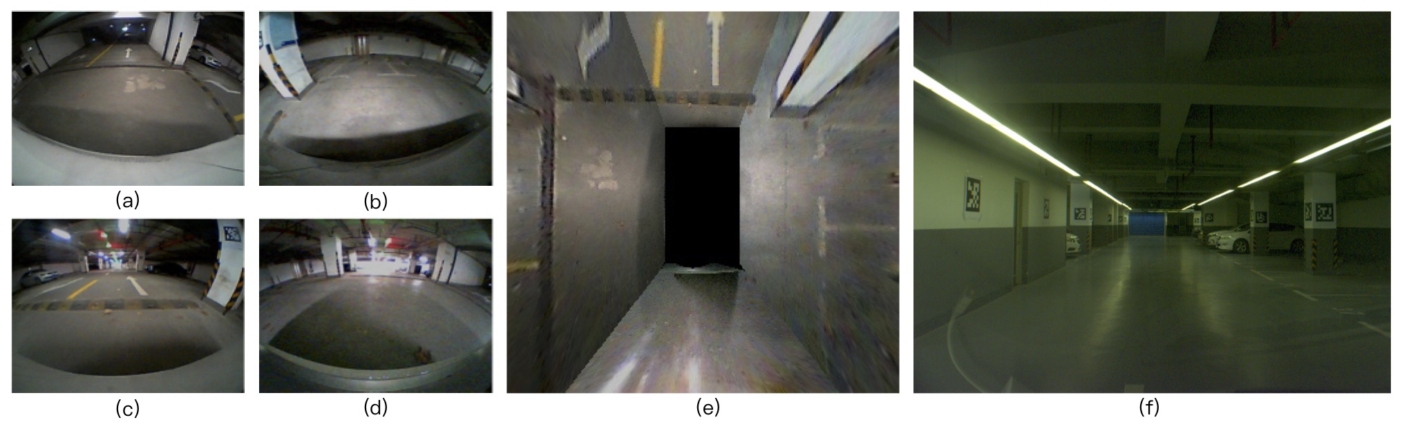
Our semantic VSLAM system includes four fisheye cameras and one monocular camera. Four fisheye cameras are fixed at two reflectors, and at the front and rear bumpers, which consist a surround-view system. A top-view image is then fused from the surround-view inputs after intrinsic and extrinsic calibration, as shown in Fig. 2. In the top-view image, which indicates ground textures, parking slots are detected. The monocular camera is installed to the left of the rear-view mirror to capture front-view scenes. The steering wheel angle, as well as the vehicle speed and heading direction collected by IMU, are also used in our system.
Our parking slot detector is based on [16], in which corner points of parking slots are detected and assembled(Fig. 3). Although the CNN-based method is capable of detecting most kinds of corner points fast and robust, the exact shape of the parking slot cannot be known due to the limited visible range of the surround vision system. As a result, the parking slot can only be guessed initially and we have to optimize the shape of the parking slots in the SLAM system. Furthermore, the ID of each parking slot should be detected for facilitating data association between parking slots, which will be elaborated in Sec. III-A.
Another kind of landmark used in our system is the visual fiducial marker. Fiducial markers are introduced as an aid for the constancy of localization since few parking lots are detected near the entrances and exits. We select AprilTags as fiducial tags for its robustness and high-efficiency [22].
III-A CNN based Parking slot Recognition
We adopt the method proposed by [16] to detect parking slots. It is a CNN-based slot detection method who detect parking slots from calibrated top-view images. Slot detection is achieved by firstly recognize the corner patterns from the image. Fig. 3(a) illustrates the examples of detected corner patterns. Since all the corners of a parking slot may not be entirely observable, the parking slots are estimated according to their entrance-lines (Fig. 3(b)), which are determined by the configuration of patterns. Several constraints are applied to robustify the detection result. The entrance-line candidate who contains more than two corner patterns is removed to avoid repeated detection. Extremely large or small candidates are also discarded since all slots are around the same size.
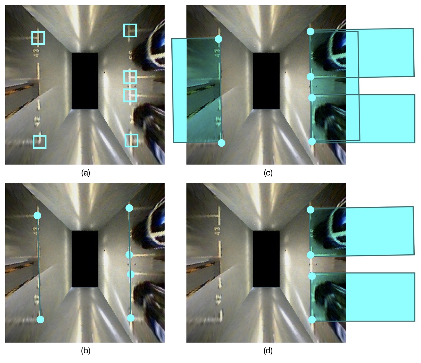
A slots’ shape and direction can serve the further parking and obstacle-avoiding task. Hence, the precision of a slot’s shape and direction are as crucial as that of its position. To optimize all of them, an additional rectangular constraint is added.A parking slot is represented by four landmark points. Each point is connected with other three by a rectangular constraint, according to an angular constraint of high confidence and a distance constraint with relatively lower confidence. The slot is then connected to the global map as an entirety.
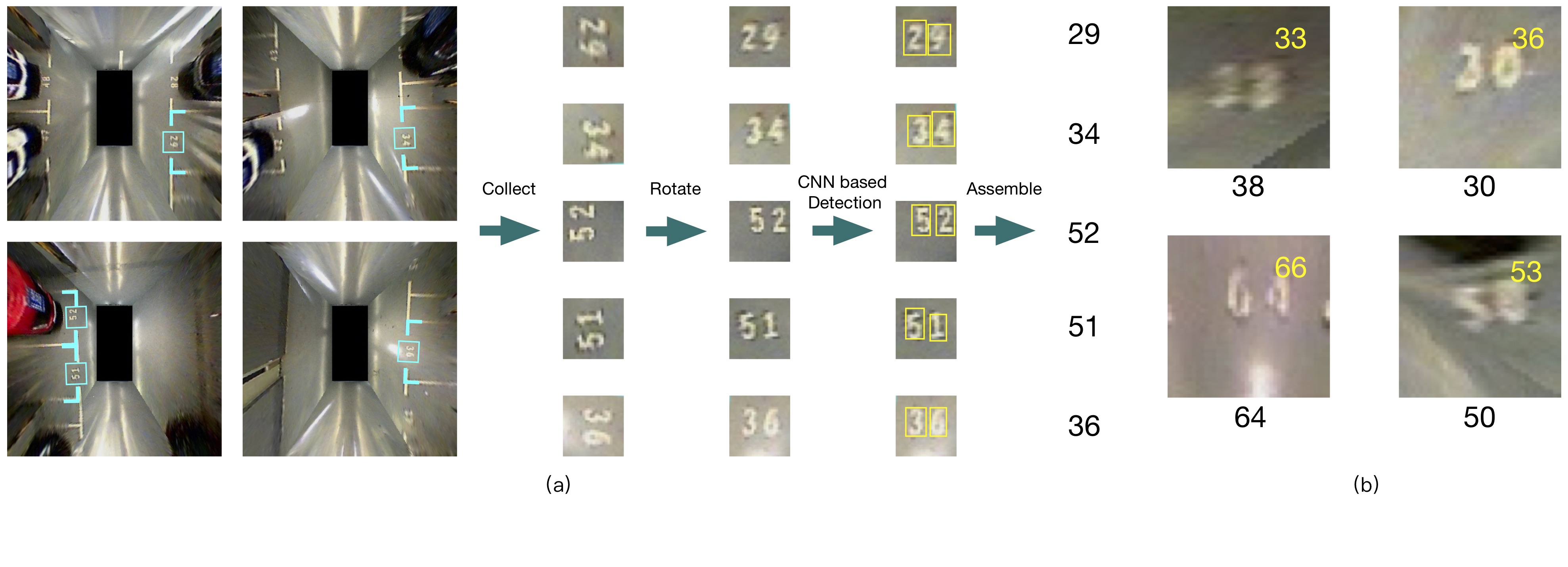
IDs of parking slots are essential for the association of this semantic landmark. We fine-tuned PVANet to detect each digit in one slot ID [12]. Slot IDs have their fixed position, so entrance-lines of parking slots help locate IDs roughly (Fig. 4 (a)). Then image patches containing slot IDs are extracted and detected. Unfortunately, due to the distorted and blurred texture in the surround view image, even the sophistic detection network could not offer the satisfactory performance. So we devised a semantic-assisted association method to cope with the uncertainty, which will be detailed in Sec. III-C.
III-B Visual fiducial tag localization
The surround view system offers an intuitive ground observation at a high frame rate, but the visibility range and resolution of the top-view image are far from satisfactory, limiting the slot detection performance. And the calibration for image fusion becomes inaccurate as time goes, which will deteriorate the slot measurement.
Recalling the goal of our practical localization system for autonomous driving and parking in parking lots, certain numbers of faithful landmarks such as visual fiducial markers still have to be incorporated.
We adopted AprilTag and employed the detection framework from the AprilTag C source Open Library 333https://april.eecs.umich.edu/wiki/AprilTags [22]. Moreover, the relative position between fiducial tags and the vehicle are solved by the PnP model [9] in a fast and accurate way.
In the PnP model, we assume four corner points of the tag always lie on the same plane, and thus definite the hypothetical 3D tag coordinate(Fig. 5).The relationship between the tag corner in the image and that in the hypothetical 3D tag coordinate can be described as
,
where and are the relative rotation and translation vector, is the intrinsic camera matrix, is the coordinate in the hypothetical 3D tag coordinate and is the homogeneous coordinate in the image plane.
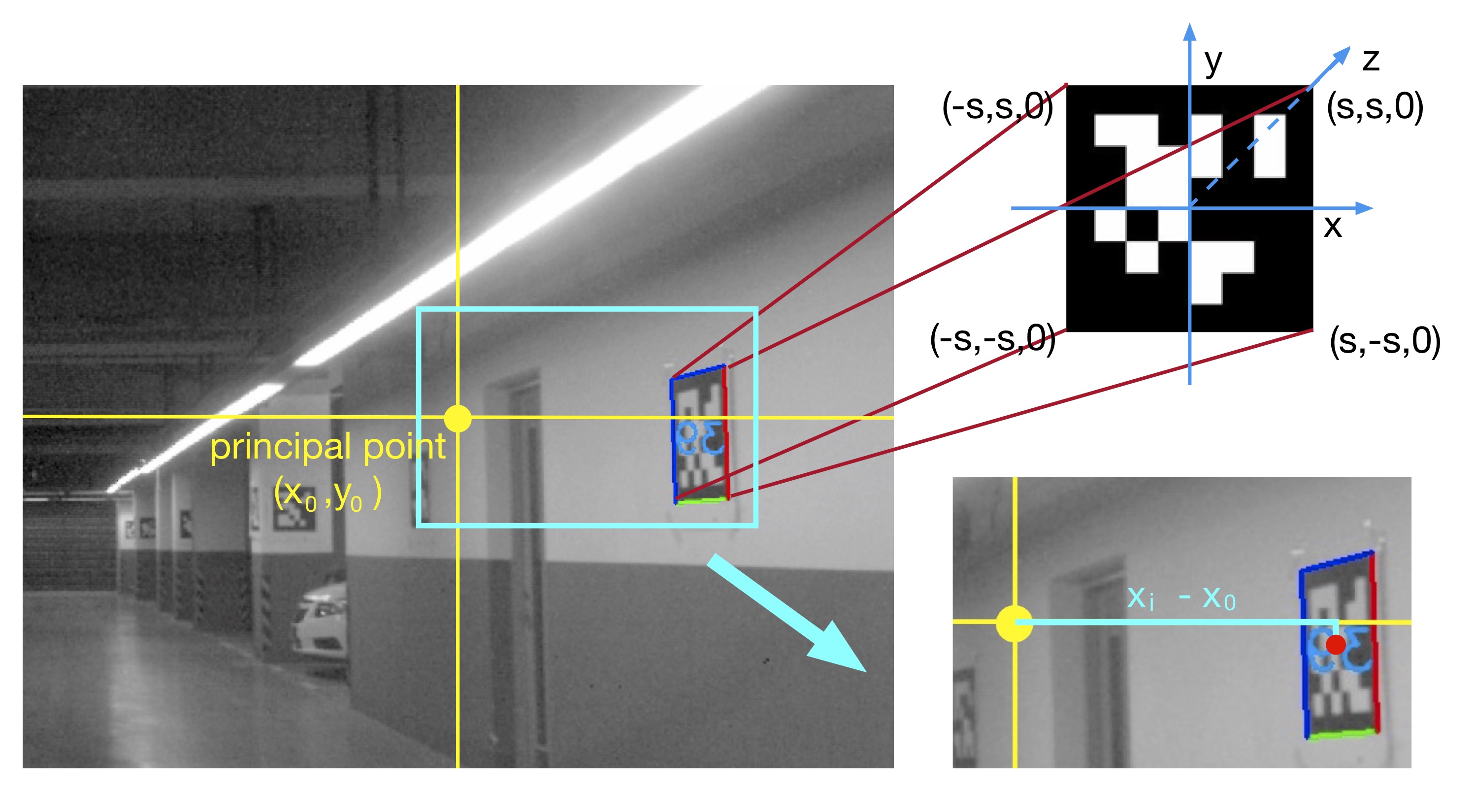
In PnP method, the solution is not always reliable since the initial value greatly affects the iteration result. So we also get the angle directly from the calibrated image and compares the value with to evaluate whether PnP method works. As shown in Fig. 5, the angle can directly be calculated by
,
where and denote the x coordinate value of the tag center and the principal point respectively, and is the focal length. The distance is the 2-norm of . So the tag locates at in the vehicle relative coordinate.
These visual fiducial markers are flexible and easily implemented. They brought another benefit for the autonomous parking purpose; those fiducial markers can easily indicate the existences of pillars and walls which can only be robustly detected by expensive laser scanners. This obstacle information can facilitate the route planning inside of a parking lot.
III-C Optimization
III-C1 Optimization Framework
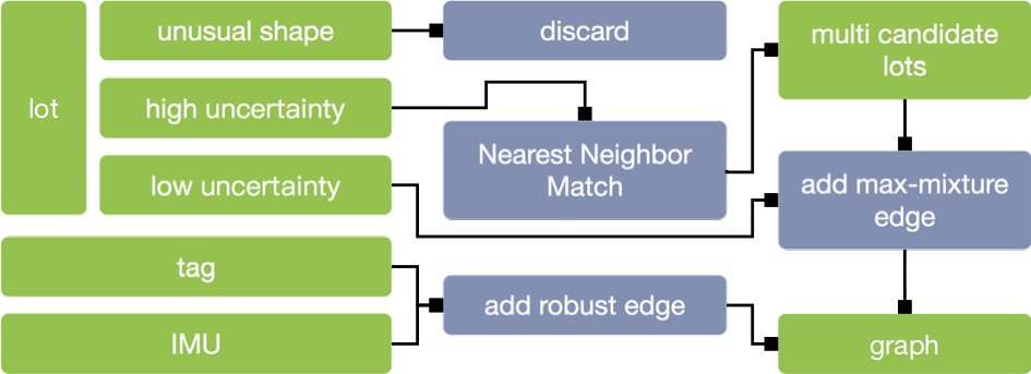
We adopt a Graph-based optimization back-end [14]. However, due to fallible detection of parking slots and their IDs from low-quality surround vision images, ambiguities will be presented during data association, which significantly affect the mapping and localization. Thus, the correct association should be ensured and wrong ones should be detected and discarded in the optimization. These are performed at both the front-end and the back-end. At each frame, parking slot observations are pre-associated through their IDs and the nearest neighbor search. The nearest neighbor is based on the relative offsets between landmarks, which is derived from a Kalman-based extrapolation with the steering wheel, car speed and the compass readings from a cheap IMU as the inputs.
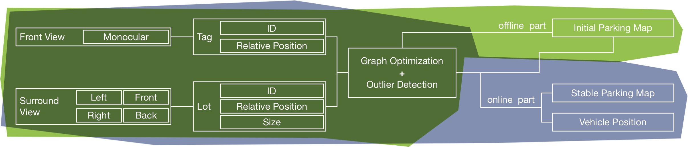
We further added the pre-associated landmarks into our graph model based on a Max-Mixture model [24]. The detailed optimization pipeline is shown in Fig. 6.
III-C2 Outliers elimination using Max-Mixture Model
Classical graph optimization method using uni-model Gaussian is sensitive to outliers and fails when there are wrongly associations in graphs. Several robust methods [28, 15, 1, 23] have been proposed solely for pose graph. Hence they can not be directly used in our landmark-based method. However, after several modifications, the Max-Mixture method can help not only eliminate errors in revisiting landmarks, but also correct wrongly associated slot IDs.
Max-Mixture describes observation ambiguities with multi-model Gaussians. Therefore, wrongly associated data can be suppressed by other mixture elements. The Likelihood function of landmark is expressed by a max-mixture of Gaussians [23]:
where and denotes the Gaussian distribution and weight of the observation .
In this paper, semantics attached to landmarks, the slot IDs, are used to evaluate slot observations’ uncertainties. A map-scale nearest neighbor search offers candidates for slot observations with highly uncertain IDs. Partially detected slot IDs (only one in two digits is recognized) also provide data associating alternatives. Afterward, all candidates are added to the factor graph, and only the ”max candidate,” who has the minimum residual is reserved. Slot observation with neither high confidence ID nor nearest neighbor candidates is a potential new slot candidate and will be ”lazily” added to the map.
IV EXPERIMENT
In this section, we test our method both online and offline. All the parking lot datasets are collected and tested by TiEV autonomous vehicle444cs1.tongji.edu.cn/tiev. We choose a parking lot, who has an area of over 3000 square meters in Jiading Campus, Tongji University, as our test parking lot. The dim lighting in the parking lot largely reduces images’ quality, while too much light coming from the entry make some of the images overexposed. Other intruders included pedestrians and vehicles passed by.
Since GPS-based localization methods fail to work correctly in the indoor parking lot, the ground truth is not available. The standard deviation of the automatically repeated vehicle traces is 0.3m, which is considered as the system accuracy in our situation.
IV-A Offline mapping test
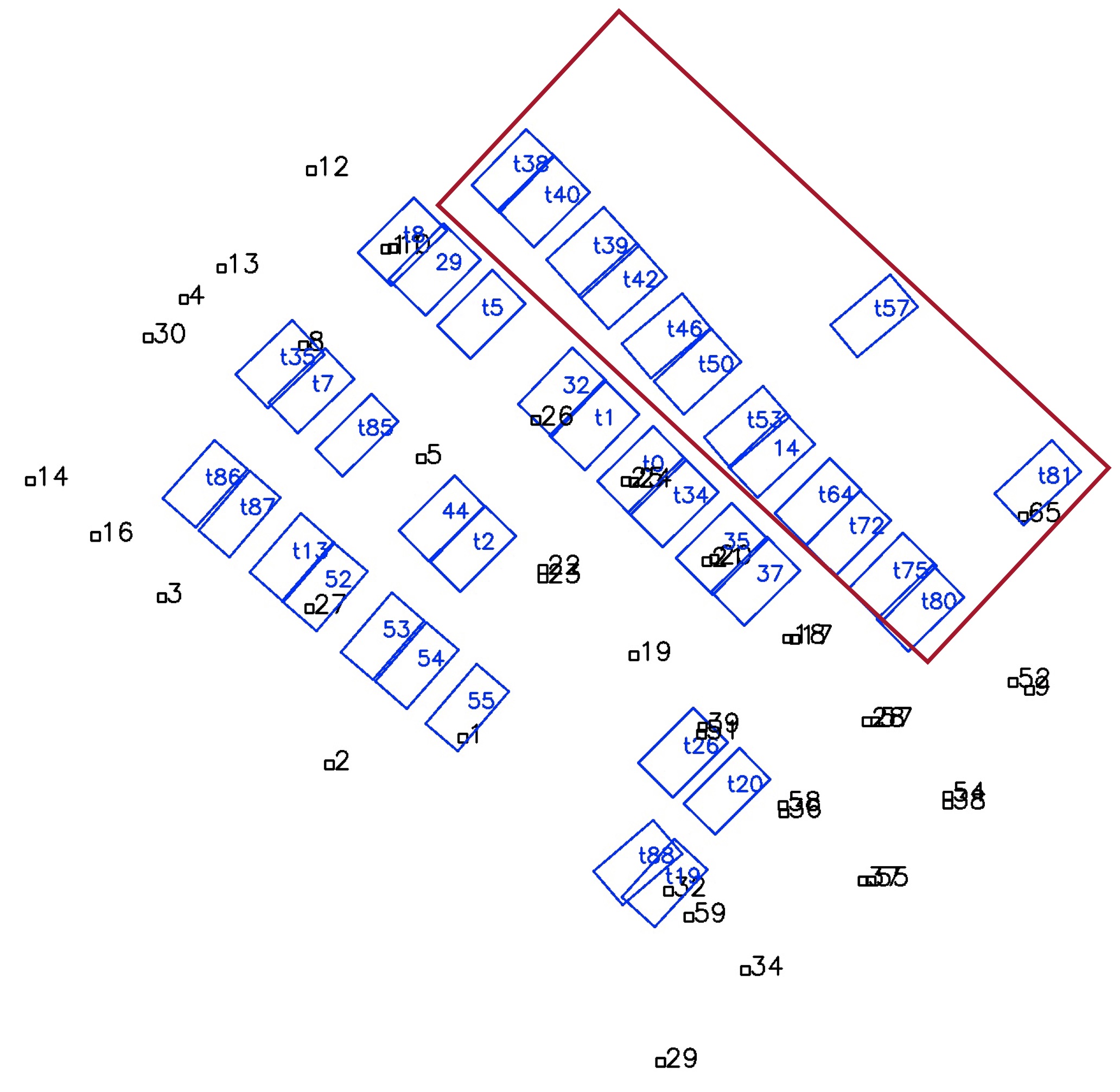
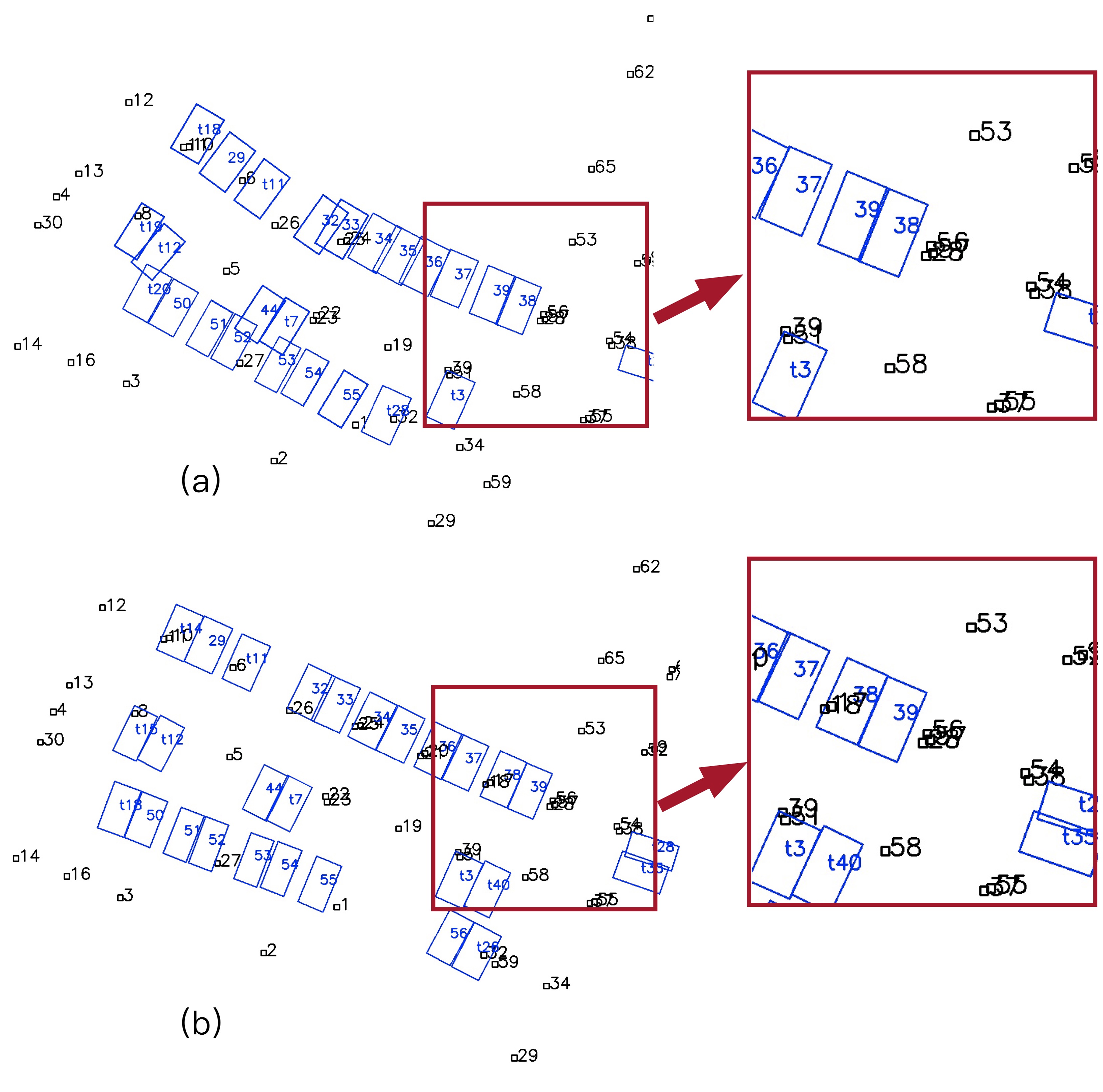
In the offline experiment, several datasets with different starting points are collected. Each dataset is processed independently. The covariance of each observation shifts from 0.1 to 0.25 according to its category and confidence level. Fig. 7 shows the map results of the experimental area. It maps an extra area of the parking lot without the auxiliary fiducial tags as shown by the red box. All the parking slots are successfully mapped to the occupied areas of warehouses and staircases represented by vacancies. The undetected parking IDs affect little of the mapping result, as shown in Fig. 7, by the slots with IDs starting with ”t.” We compared the mapping results with and without robust method; the result is shown in Fig. 8. In Fig. 8(a), some slots are wrongly associated with others due to the wrongly detected slot IDs, causing a global ambiguity. e.g. slot No.39 is wrongly recognized as No.38 when firstly identified, and the ID of two slots reversed. In Fig. 8(b), robust method avoided this from happening by choosing a more reasonable hypothesis.
IV-B Online real-time mapping and localization
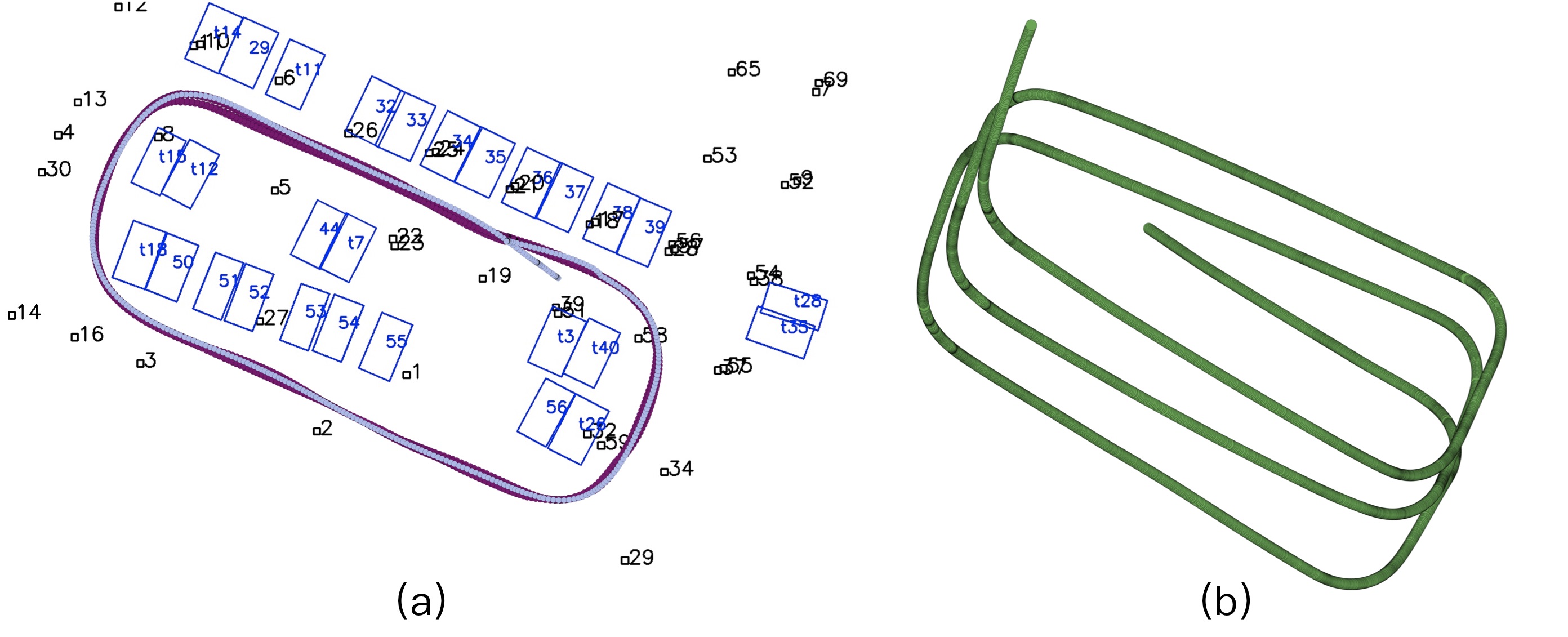
During the online experiment, the vehicle is first operated by a human driver to initialize the parking map. Once the map stabilizes, a car trace is recorded. Then the vehicle drives automatically at the speed of 3-5 km/h following this pre-recorded trace according to the real-time localization. The frequency of online part is 10Hz. The automatic driving procedure is repeated more than ten times; traces are also recorded and compared with the pre-recorded one. Fig. 9 shows the traces of both manual (nattier blue) and automatic driving trace (claret).
During the experiment, quite a number of fiducial tags (60 tags) are used to cover the lot-free parts near the entrance and to guarantee a sufficiently stable and credible localization result.
Each tag is printed on an A2-size paper with 48.8 cm side length. While observing, those tags which are 20 meters or farther than the vehicle are discarded since the accuracy decreases as tags become smaller or even unreadable in the image. These fiducial tags enable the vehicle to pass through the 3 meters’ wide entrance and the long corridor without slots nearby, hence, ensure the robust localization performance.
V CONCLUSION
Due to the various illumination conditions, parking slot is a harsh environment for most SLAM method. We detect the semantic landmark, parking slots with IDs, in a parking lot, and build the semantic parking incrementally. In this procedure, semantic data association is vital. To associate all the semantic information robustly, a robust method for pose graph, Max-Mixture, is utilized and improved. Experiment in parking lot shows the effectiveness of our system. However, we use fiducial tags as an aid for loop closure, which is not practical in many circumstances. In the future work, we aim to replace fiducial tags with other semantic clues including instruction arrows or parking signs on the pillars and improve the adaptability of our system.
References
- [1] P. Agarwal, G. D. Tipaldi, L. Spinello, C. Stachniss, and W. Burgard, “Robust map optimization using dynamic covariance scaling,” in Robotics and Automation (ICRA), 2013 IEEE International Conference on. IEEE, 2013, pp. 62–69.
- [2] A. Bansal, H. Badino, and D. Huber, “Analysis of the cmu localization algorithm under varied conditions,” Robotics Institute, Pittsburgh, PA, Tech. Rep. CMU-RI-TR-15-05, January 2015.
- [3] C. Cadena, L. Carlone, H. Carrillo, Y. Latif, D. Scaramuzza, J. Neira, I. Reid, and J. J. Leonard, “Past, Present, and Future of Simultaneous Localization And Mapping: Towards the Robust-Perception Age,” arXiv.org, June 2016.
- [4] A. J. Davison, “Real-time simultaneous localisation and mapping with a single camera,” in IEEE International Conference on Computer Vision, 2003, p. 1403.
- [5] J. Engel, V. Koltun, and D. Cremers, “Direct sparse odometry.” IEEE Transactions on Pattern Analysis & Machine Intelligence, vol. PP, no. 99, pp. 1–1, 2017.
- [6] J. Engel, T. Schöps, and D. Cremers, “Lsd-slam: Large-scale direct monocular slam,” in European Conference on Computer Vision, 2014, pp. 834–849.
- [7] C. Forster, M. Pizzoli, and D. Scaramuzza, “Svo: Fast semi-direct monocular visual odometry,” in IEEE International Conference on Robotics and Automation, 2014, pp. 15–22.
- [8] H. Grimmett, M. Buerki, L. Paz, and P. Pinies, “Integrating metric and semantic maps for vision-only automated parking,” in IEEE International Conference on Robotics and Automation, 2015, pp. 2159–2166.
- [9] R. Hartley and A. Zisserman, Multiple View Geometry in Computer Vision. Cambridge University Press, 2003.
- [10] W. Hess, D. Kohler, H. Rapp, and D. Andor, “Real-time loop closure in 2d lidar slam,” in Robotics and Automation (ICRA), 2016 IEEE International Conference on. IEEE, 2016, pp. 1271–1278.
- [11] M. Himstedt and E. Maehle, “Online semantic mapping of logistic environments using rgb-d cameras,” International Journal of Advanced Robotic Systems, vol. 14, no. 4, p. 1729881417720781, 2017.
- [12] S. Hong, B. Roh, K. Kim, Y. Cheon, and M. Park, “Pvanet: Lightweight deep neural networks for real-time object detection,” CoRR, vol. abs/1611.08588, 2016. [Online]. Available: http://arxiv.org/abs/1611.08588
- [13] S. Houben, M. Neuhausen, M. Michael, R. Kesten, F. Mickler, and F. Schuller, “Park marking-based vehicle self-localization with a fisheye topview system,” Journal of Real-Time Image Processing, pp. 1–16, Sept. 2015.
- [14] R. Kümmerle, G. Grisetti, H. Strasdat, K. Konolige, and W. Burgard, “G2o: A general framework for graph optimization,” in IEEE International Conference on Robotics and Automation, 2011, pp. 3607–3613.
- [15] Y. Latif, C. Cadena, and J. Neira, “Robust loop closing over time for pose graph slam,” The International Journal of Robotics Research, vol. 32, no. 14, pp. 1611–1626, 2013.
- [16] L. Li, L. Zhang, X. Li, X. Liu, Y. Shen, and L. Xiong, “Vision-based parking-slot detection: A benchmark and a learning-based approach,” 2017 IEEE International Conference on Multimedia and Expo (ICME), pp. 649–654, 2017.
- [17] X. Li and R. Belaroussi, “Semi-dense 3d semantic mapping from monocular SLAM,” CoRR, vol. abs/1611.04144, 2016. [Online]. Available: http://arxiv.org/abs/1611.04144
- [18] F. Lu and E. Milios, “Globally consistent range scan alignment for environment mapping,” Autonomous robots, vol. 4, no. 4, pp. 333–349, 1997.
- [19] J. Mccormac, A. Handa, A. Davison, S. Leutenegger, J. Mccormac, A. Handa, A. Davison, and S. Leutenegger, “Semanticfusion: Dense 3d semantic mapping with convolutional neural networks,” in IEEE International Conference on Robotics and Automation, 2017, pp. 4628–4635.
- [20] M. Montemerlo and S. Thrun, “Fastslam 2.0,” FastSLAM: A scalable method for the simultaneous localization and mapping problem in robotics, pp. 63–90, 2007.
- [21] R. Mur-Artal, J. M. M. Montiel, and J. D. Tardós, “Orb-slam: A versatile and accurate monocular slam system,” IEEE Transactions on Robotics, vol. 31, no. 5, pp. 1147–1163, 2017.
- [22] E. Olson, “Apriltag: A robust and flexible visual fiducial system,” in IEEE International Conference on Robotics and Automation, 2011, pp. 3400–3407.
- [23] E. Olson and P. Agarwal, “Inference on networks of mixtures for robust robot mapping,” The International Journal of Robotics Research, vol. 32, no. 7, pp. 826–840, 2013.
- [24] M. Pfingsthorn and A. Birk, “Representing and solving local and global ambiguities as multimodal and hyperedge constraints in a generalized graph slam framework,” in IEEE International Conference on Robotics and Automation, 2014, pp. 4276–4283.
- [25] R. F. Salas-Moreno, R. A. Newcombe, H. Strasdat, P. H. J. Kelly, and A. J. Davison, “Slam++: Simultaneous localisation and mapping at the level of objects,” in Computer Vision and Pattern Recognition, 2013, pp. 1352–1359.
- [26] D. Stojanović and N. Stojanović, “Indoor localization and tracking: Methods, technologies and research challenges,” Facta Universitatis, Series: Automatic Control and Robotics, vol. 13, no. 1, pp. 57–72, 2014.
- [27] H. Strasdat, J. Montiel, and A. J. Davison, “Real-time monocular slam: Why filter?” in Robotics and Automation (ICRA), 2010 IEEE International Conference on. IEEE, 2010, pp. 2657–2664.
- [28] N. Sünderhauf and P. Protzel, “Switchable constraints for robust pose graph slam,” in Intelligent Robots and Systems (IROS), 2012 IEEE/RSJ International Conference on. IEEE, 2012, pp. 1879–1884.
- [29] S. Thrun and Y. Liu, “Multi-robot slam with sparse extended information filers,” Robotics Research, pp. 254–266, 2005.
- [30] G. Younes, D. C. Asmar, and E. A. Shammas, “A survey on non-filter-based monocular visual slam systems,” CoRR, vol. abs/1607.00470, 2016.