Printing-while-moving: a new paradigm for large-scale robotic 3D Printing
Abstract
Building and Construction have recently become an exciting application ground for robotics. In particular, rapid progress in materials formulation and in robotics technology has made robotic 3D Printing of concrete a promising technique for in-situ construction. Yet, scalability remains an important hurdle to widespread adoption: the printing systems (gantry-based or arm-based) are often much larger than the structure to be printed, hence cumbersome. Recently, a mobile printing system – a manipulator mounted on a mobile base – was proposed to alleviate this issue: such a system, by moving its base, can potentially print a structure larger than itself. However, the proposed system could only print while being stationary, imposing thereby a limit on the size of structures that can be printed in a single take. Here, we develop a system that implements the printing-while-moving paradigm, which enables printing single-piece structures of arbitrary sizes with a single robot. This development requires solving motion planning, localization, and motion control problems that are specific to mobile 3D Printing. We report our framework to address those problems, and demonstrate, for the first time, a printing-while-moving experiment, wherein a 210 cm 45 cm 10 cm concrete structure is printed by a robot arm that has a reach of 87 cm.
I Introduction
Digital fabrication in construction has become one of the main foci of robotic research in recent years, with the perspective of fully autonomous construction. While various in-situ construction approaches have been demonstrated for steel-frame building and brick wall construction [1, 2, 3, 4], there is also active research in concrete robotic 3D Printing, which we review in detail in Section II.
Despite rapid developments in printable material formulation [5, 6, 7] and system design, scalability remains a major hurdle to the widespread adoption of concrete 3D printing in B&C. For most of the existing gantry-based and arm-based printing systems, the sizes of the printed structures are constrained either by the limited volume of the gantry, or by the reach of the robot arm. To alleviate the scalability issue, some mobile printing systems have been demonstrated, where a robot manipulator is mounted on a mobile platform to perform the printing [8]. However, up to now, the printing can only be executed when the printer is stationary, which still places limitations on the size of structures that can be printed in a single take.

In this paper, we propose a 3D printing system that implements printing-while-moving paradigm. This paradigm enables printing single-piece structures of arbitrary sizes with a single mobile robot printer. We demonstrate, for the first time, the actual printing of a single-piece concrete structure by a mobile robot printer. The size of the structure is 210 cm 45 cm 10 cm (length, width, height), which is larger than the reach of the robot arm (87 cm).
Achieving printing-while-moving requires addressing several challenges. The motions of the robot manipulator and the mobile platform must be carefully planned and coordinated. In addition, precise robot localization and feedback motion control are necessary to ensure that the nozzle deposits concrete at the right place and with the right speed. This is particularly important in the layer-by-layer process at hand: nozzle position offsets of more than 1 cm between two consecutive layers can cause the structure to collapse.
The remainder of this article is organized as follows. In Section II, we review existing 3D Printing systems for B&C. In Section III, we present in detail the proposed mobile printing system. In Section IV, we report the results of the accuracy and precision assessment, as well as the actual printing experiment. In Section V, we conclude by discussing the limitations of our current system and sketch some directions for future work.
II Related work
Many groups work on automatizing construction process using 3D printing techniques and suggested different methods. One of the widely adopted methods is gantry-based concrete 3D printers [9, 10, 11]. Due to the resemblance to the conventional additive manufacturing methods with printing nozzle moving in the Cartesian space, it is relatively easier to design the printer itself, and it is also straightforward to slice the printed shape and plan the motion of the nozzle. However, the printing area of these systems is limited to the space enclosed by the gantry. Thus, it is not possible to print any construction wider than the foothold distance of the gantry. Moreover, these system are in general extremely heavy and requires pre-installation on the printing site before each printing operation.
Another class of widely used 3D concrete printing systems is the arm-based systems [12, 13]. These systems offer more flexible printing experience as they can orient their nozzle in 3 dimensional rotational space. Therefore, these systems can potentially print more complex contours. In addition, installation process of these system on the printing site is relatively easier than the gantry-based systems. However, they can still only print inside of the reachable space of the arm, and this space is further limited with the orientation of the nozzle and kinematic singularities at some parts of the reachable space.
In order to resolve scalability problem of the arm-based approaches, there are some groups proposing arm-based printing systems on a mobile base. Digital Construction Platform (DCP) by MIT [13] is one of the examples of such systems. The DCP is composed of a robot arm, which can reach radially and vertically, and a track based nonholonomic mobile platform. This system uses printing-upon-arrival strategy, hence it works in a quasi-static manner. Once it moves into the printing site, it stabilizes itself to the ground and prints later. This approach does not only limit the size of structure to be printed, but also limits the shape of the structure, since at the end of the printing mobile printer should be able to leave the printing site. Another example of mobile concrete 3D printers is our previous work [8], in which multiple arm-based printers with holonomic mobile base are used to enlarge printable area. This printing system is also based on printing-upon-arrival strategy.
Another notable printing approach for 3D concrete printing is Minibuilders [14], which is composed of three small mobile robots. The first robot prepares a short concrete wall by following pre-installed strips. The second robot is placed on the top of the wall and continues building it while moving through the contour of the wall. The last robot performs surface finishing of the wall.
III System development
III-A Mobile printing system
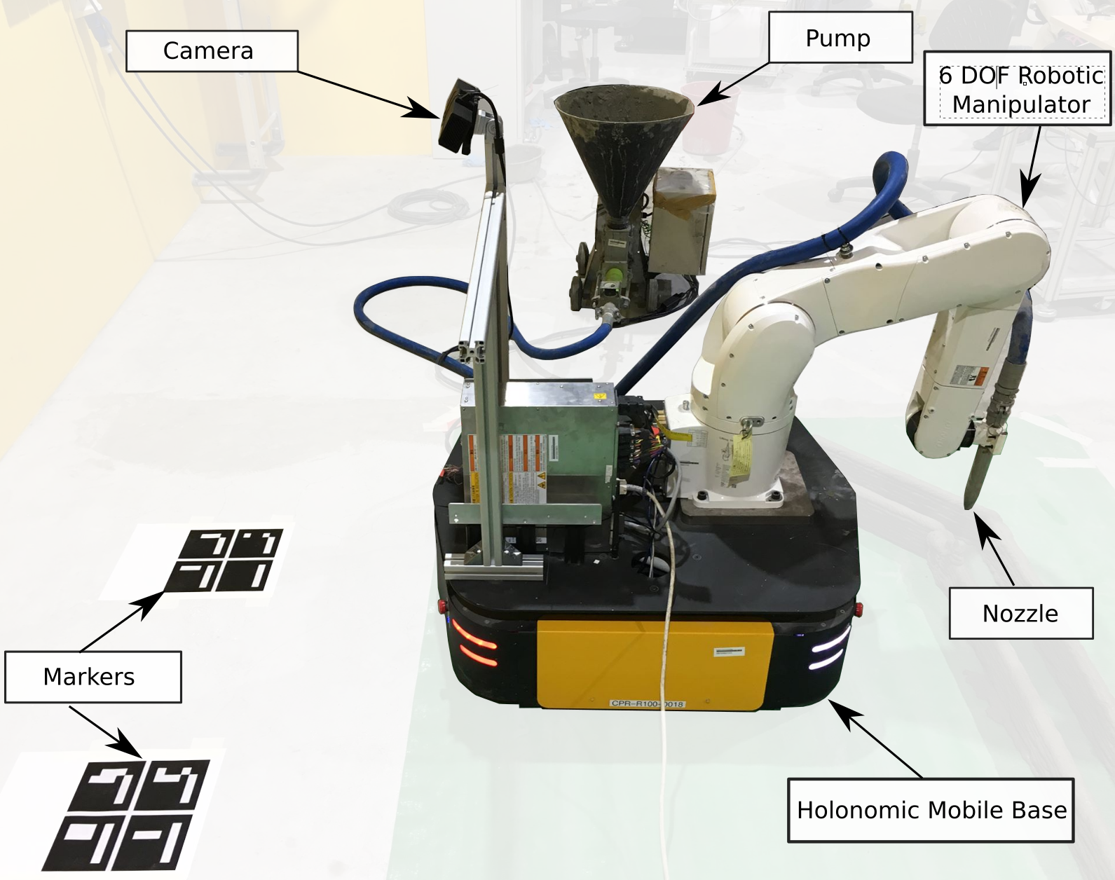
The hardware setup is mostly the same as in our previous work [8], to which the reader is referred for more details. Briefly, the system comprises: a holonomic mobile base (Clearpath Ridgeback), a 6-DoF industrial robot manipulator (Denso VS-087) mounted on top of the mobile base, a nozzle mounted on the manipulator flange and connected to a pump through a hose (Fig. 2, Top).
The main difference with [8] is that the stereo camera (Microsoft Kinect for Xbox One) is mounted on the back of the mobile base, instead of being stationary. Conversely, the Aruco markers [15] of size 12 cm12 cm are placed on the ground, instead of being placed on the robot as in [8]. This change enables the localization system to be continuously effective in a larger area.
During execution, while the mobile base runs with its own battery, the robot arm’s power is supplied externally. Image processing, sensor fusion and motion planning are performed on an off-board computer.
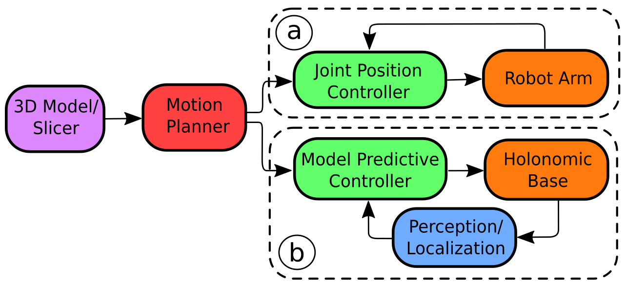
The pipeline of the process is depicted in Fig. 2, Bottom. From the 3D model of the desired object, we first plan, offline, the coordinated motions of the mobile base and the robot arm in order to print the object layer by layer (Motion planning). Next, we execute the planned motions on the actual platform. During execution, the position of the mobile base is monitored in real-time (Localization), and feedback control is exercised to track the planned motions as close as possible (Motion control). The following sections detail these processes.
III-B Motion planning
Compared to standard motion planning for a 6-DoF manipulator to cover a large workspace (see e.g. [16]), the present motion planning problem involves two additional difficulties
-
•
The continuous printing process precludes switching between different Inverse Kinematics (IK) classes [17];
-
•
The mobile base adds three extra (redundant) DoFs, as well as additional collision possibilities (between the robot and the base, or between the base and the printed specimen).
To address these issues, we take the following simplified approach:
-
1.
Prescribe a reasonable motion for the base, avoiding collision with the to-be-printed specimen and taking into account the manipulator reachability (Fig. 3);
-
2.
Synchronize the base motion with the nozzle motion (which follows the design of the specimen and has constant speed in order to deliver the printing materials at a constant rate);
-
3.
Given the base motion and the nozzle motion, compute the joint trajectories for the manipulator by differential IK (see e.g. [17]).
Note that this approach is not optimal and is not guaranteed to always work. For instance, the differential IK of step 3 might not find any continuous motion for the manipulator, given the prescribed base and nozzle motions. Developing a more principled planning algorithm for mobile 3D Printing is part of our future work.
III-C Localization of the mobile base
As stated in the Introduction, the accurate control of the mobile base trajectory is crucial for printing quality. Note that, because the accuracy of the industrial robot arm is significantly higher than that of the mobile base, we make the assumption that the former is 100% accurate.
An essential component in trajectory control is localization (or pose estimation), i.e. knowing accurately where the mobile base is at any given time instant. Since the built-in localization module of the mobile base has substantial drift over time, we use a vision-based scheme: several fiducial Aruco markers are placed on the ground, and when marker is seen by the on-board camera, the position of the mobile base can be estimated by
-
•
is the estimated homogeneous transformation of the Base w.r.t. the World frame;
-
•
is the (known) transformation of Marker w.r.t. the World frame;
-
•
is the transformation of the Camera w.r.t. the marker (computed in real-time by the Aruco module [15]);
-
•
is the (known) transformation of the Base w.r.t. the Camera.
From the transformation , one can obtain the estimated position and orientation of the mobile base . Next, to compensate for the delay associated with image processing (which could be as long as 50 ms), we propagate the estimated position and orientation using the controls that were sent during the delay period by
where is the propagated estimation at time instant , is the control time step, is the number of control time steps that have passed during the delay, is the control input at time step . Grouping together all the markers that are visible to the camera at time step , one finally obtain the measurement
where is the number of visible markers at time step . We make sure that at least one marker is visible at any time instant.
Finally, we fuse the measurements with the controls using an Extended Kalman Filter
-
•
State prediction: ;
-
•
Measurement: ,
where and are respectively the prediction noise and the measurement noise at step . The values of the weight matrices and were chosen following a calibration process.
III-D Motion control for the mobile base
There are two important design objectives in the control of the mobile base: (i) track the desired trajectory accurately; (ii) obey the velocity constraints for safe autonomous operation. In order to address these objectives, we implement a Model Predictive Controller. Note that the control inputs are calculated in the world frame.
The discrete dynamics of the mobile base for a horizon of steps is given by
where , , , and .
Next, consider the errors
where the superscript indicates the desired trajectory and the nominal inputs. Note that is zero in our case. The error dynamics can then be written as
where , .
The control inputs for horizon are calculated with the following quadratic optimization
where and are block-diagonal weight matrices. The matrices , , and encode input and state constraints, see e.g. [18] for details.
IV Experiments
IV-A Accuracy and precision assessment
We used Optitrack, a Motion Capture system, with 6 cameras, to provide an independent measurement. We placed markers on the nozzle and the mobile base and capture their motions during an air printing session. Fig. 4 shows the marker trajectories for 15 laps.
Before assessing the accuracy of the system (how close the printed shape is to the desired shape), we first evaluated its precision (how repeatable the system is), which is critical in the layer-by-layer material deposition process.
Consider a segment parallel to the X-axis (segments A and C in Fig. 4). We collected all the data points corresponding to this segment across the 15 laps. We then fit a line to those data points. The precision was then quantified by the maximum and the mean error
For segments that are parallel to the Y-axis (segments B and D), we swapped the roles of and . Given the above definitions, the maximum and mean errors across the four linear segments of base motion were respectively 9.9 mm and 2.2 mm.
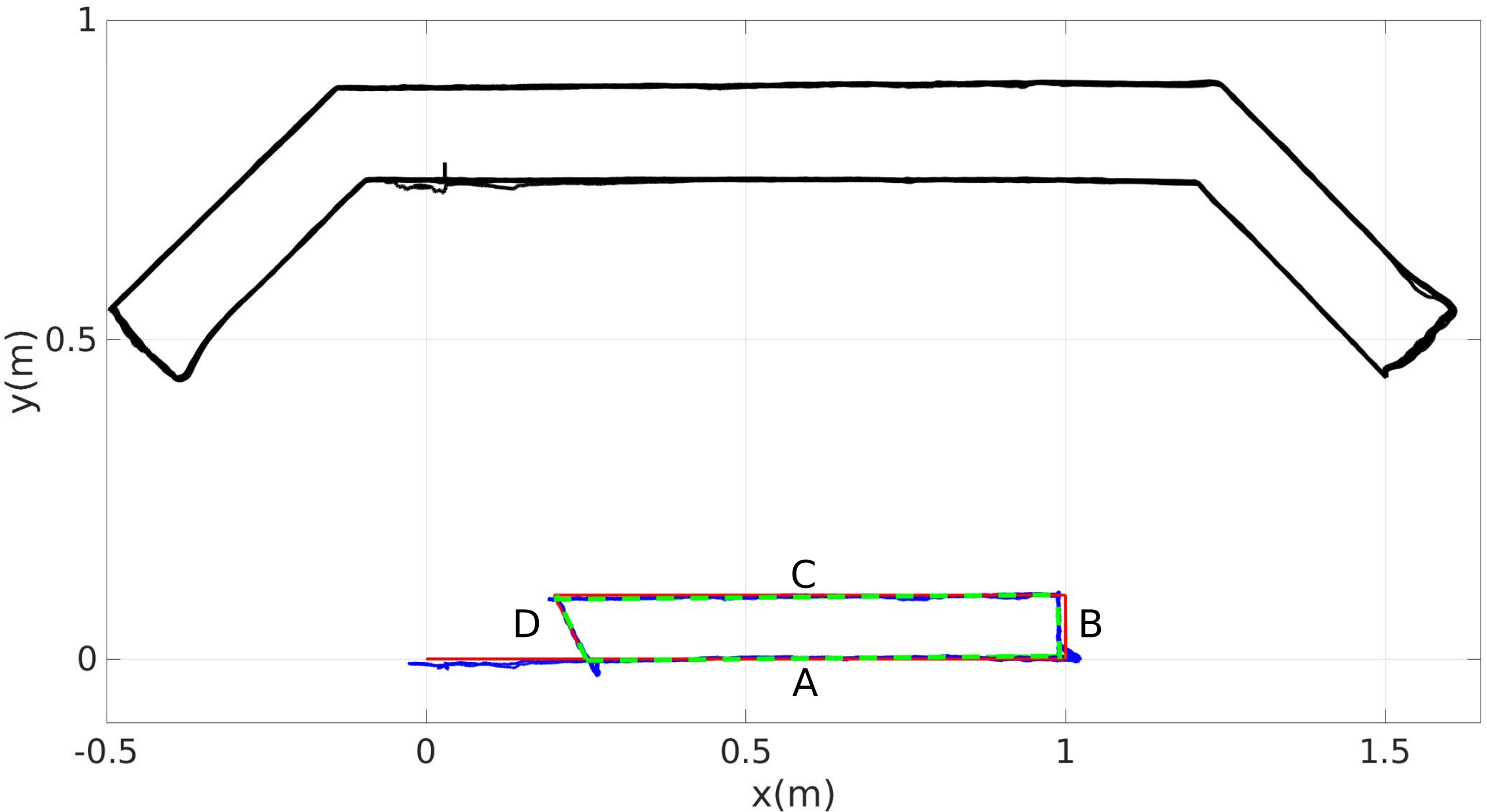
Next, to assess the accuracy, we computed the maximum distance between the fitted lines and the desired path, which was found to be 9.8 mm.
Overall, the accuracy and precision of our system are significantly better than those found in the SLAM literature. For example, a recent review reports errors of more than 20 mm in the best case [19]. Note however that our setup (use of fiducial markers) and objectives are different from the SLAM literature. In any case, the precision of our system was sufficient to print 10 layers of concrete, as shown in the next section. Upon visual inspection of the printed specimen, the print quality seems as good as in fixed-base printing.
IV-B Actual printing
We tested the mobile printing system in the laboratory environment. The structure to be printed is shown in Fig. 3 and has size a 210 cm 45 cm 10 cm, which is significantly larger than the reach of the robot arm (87 cm). We used a nozzle of diameter 1 cm and a nozzle speed of 10 cm/s. The cement was prepared as in the previous work of our group [20, 8].
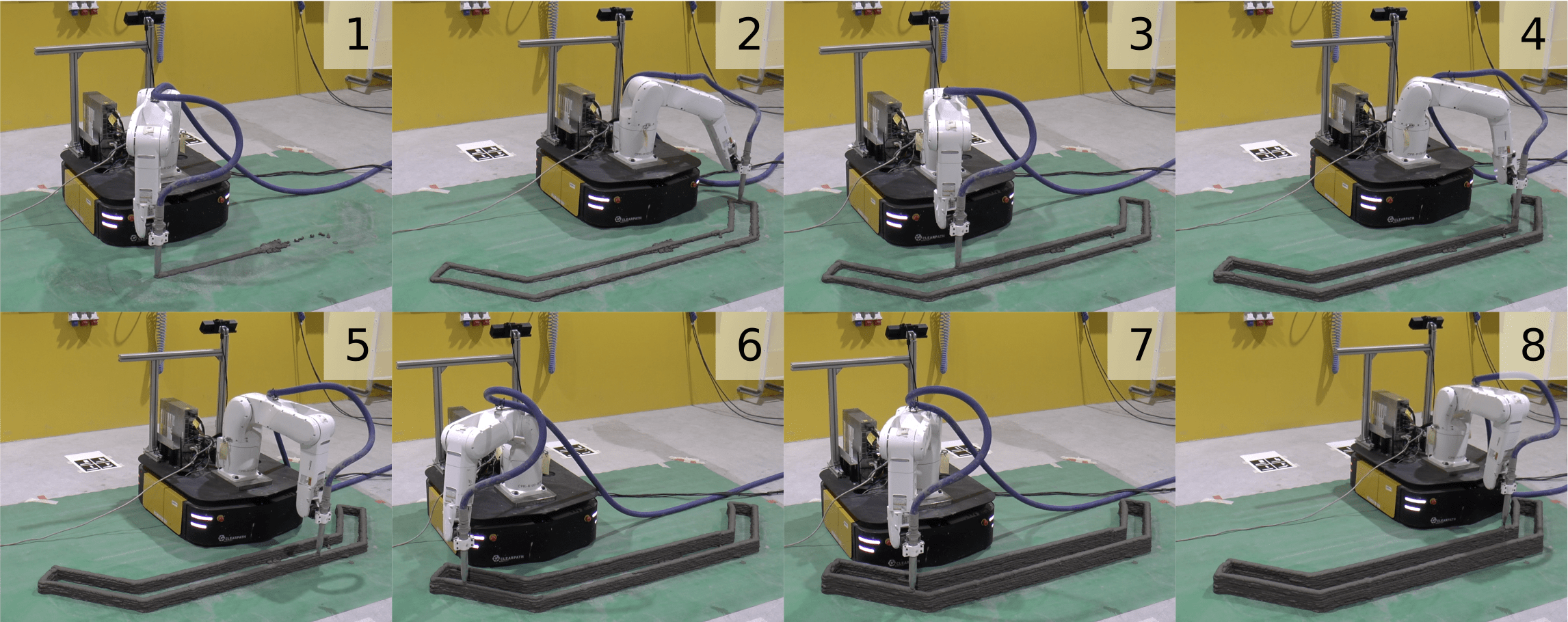
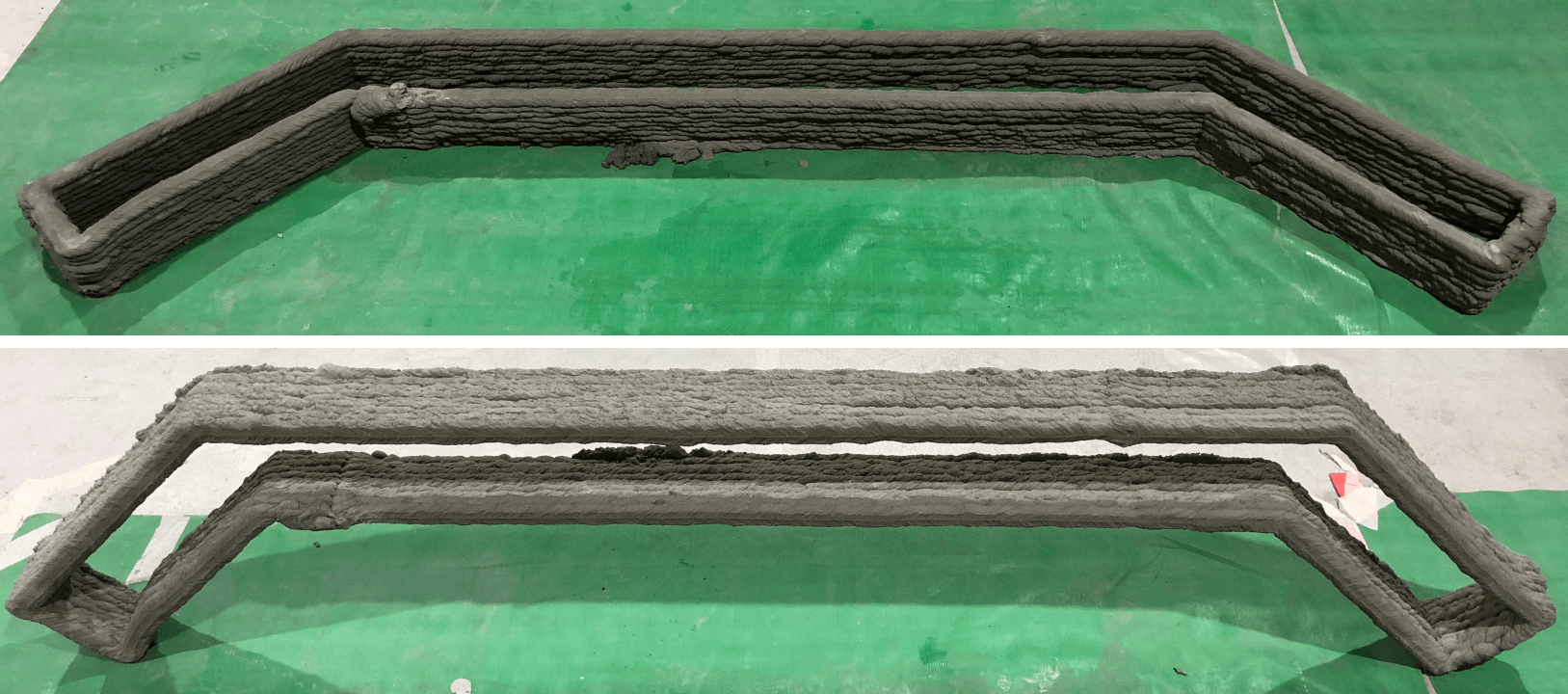
We printed the 10 layers of the structure in 9 min 16 s. A video of the experiment is available at https://youtu.be/ZIbY00iTFwY. Snapshots of the printing session are shown in Fig. 5. After three days of curing, the structure was hard enough to be flipped and put on its side, as shown in Fig. 6. As mentioned previously, the precision of our trajectory tracking enabled to obtain a surface finish similar to the specimen obtained by fixed-based printing [8].
V Conclusion
We have presented the printing-while-moving approach for large scale in-situ concrete robotic 3D Printing. Our mobile printing system is able to print single-piece concrete structures that are larger than the robot reach, in a single take. We demonstrated, for the first time, a printing-while-moving experiment, wherein a 210 cm 45 cm 10 cm concrete structure by a robot arm that has a reach of 87 cm.
Our system however still presents a number of limitations. Localization errors may come from several sources: (i) errors in the positions of the fiducial markers with respect to each other and with respect to the world frame; (ii) vibrations of the camera during the movements of the mobile base. Source (i) mainly affects the accuracy, and can be mitigated by careful calibration. Source (ii) can have a very large effect on the precision, and can be mitigated by installing proper vibration isolators for the camera. More generally, one can also integrate other sensors, such as IMU or laser scanners, or implement more sophisticated localization algorithms (e.g. based on particle filters), to improve localization.
We observed that the sharp turns at the corners affected the precision of our system in several manners. First, they cause vibrations of the camera, which affects the vision-based localization as discussed previously. Second, they cause vibrations of the nozzle, affecting the material deposition. Third, the step-like control inputs are difficult to track accurately by the physical system, causing large tracking errors at the corners (see Fig. 4). These issues can be mitigated by planning smooth paths for the mobile base, or by compensating the errors of the mobile base with fast arm motions.
Finally, the unevenness of the ground affects the quality of the printing in two ways. First, at locations where the ground level rises significantly, the extruded cement is squeezed more and spreads laterally, resulting in a thinner layer in vertical direction. Second, ground height variations also amplify the vibrations of the mobile base. Again, those issues can be mitigated by mechanical vibration isolation or by active disturbance rejection with the robotic arm.
Besides addressing the current limitations, there are also many exciting avenues for further development. For example, the multi-robot version of the presented concept can dramatically increases productivity, but is intrinsically more challenging. It requires for instance a motion planning algorithm that can plan optimal mobile base trajectories considering multiple printing paths, multi-robot collision avoidance, and material supply tethers.
Acknowledgement
This work was supported in part by the Medium-Sized Centre funding scheme (awarded by the National Research Foundation, Prime Minister’s Office, Singapore) and by Sembcorp Design & Construction Pte Ltd. We would like to thank Lim Jian Hui, Weng Yi Wei, and Lu Bing for their help with the experiment.
References
- [1] M. Giftthaler, T. Sandy, K. Dörfler, I. Brooks, M. Buckingham, G. Rey, M. Kohler, F. Gramazio, and J. Buchli, “Mobile robotic fabrication at 1:1 scale: the in situ fabricator,” Construction Robotics, vol. 1, no. 1, pp. 3–14, Dec 2017. [Online]. Available: https://doi.org/10.1007/s41693-017-0003-5
- [2] T. Wangler, E. Lloret, L. Reiter, N. Hack, F. Gramazio, M. Kohler, M. Bernhard, B. Dillenburger, J. Buchli, N. Roussel, and R. Flatt, “Digital concrete: Opportunities and challenges,” RILEM Technical Letters, vol. 1, pp. 67–75, 2016. [Online]. Available: https://letters.rilem.net/index.php/rilem/article/view/16
- [3] K. Dörfler, T. Sandy, M. Giftthaler, F. Gramazio, M. Kohler, and J. Buchli, Mobile Robotic Brickwork. Cham: Springer International Publishing, 2016, pp. 204–217. [Online]. Available: https://doi.org/10.1007/978-3-319-26378-6_15
- [4] M. Lussi, T. Sandy, K. Dörfler, N. Hack, F. Gramazio, M. Kohler, and J. Buchli, “Accurate and adaptive in situ fabrication of an undulated wall using an on-board visual sensing system,” in 2018 IEEE International Conference on Robotics and Automation, 2018.
- [5] T. T. Le, S. A. Austin, S. Lim, R. A. Buswell, R. Law, A. G. Gibb, and T. Thorpe, “Hardened properties of high-performance printing concrete,” Cement and Concrete Research, vol. 42, no. 3, pp. 558–566, 2012.
- [6] B. Zareiyan and B. Khoshnevis, “Interlayer adhesion and strength of structures in contour crafting-effects of aggregate size, extrusion rate, and layer thickness,” Automation in Construction, vol. 81, pp. 112–121, 2017.
- [7] Y. W. Tay, B. Panda, S. C. Paul, M. J. Tan, S. Z. Qian, K. F. Leong, and C. K. Chua, “Processing and properties of construction materials for 3d printing,” Materials Science Forum, vol. 861, pp. 177–181, 2016.
- [8] X. Zhang, M. Li, J. H. Lim, Y. Weng, Y. W. D. Tay, H. Pham, and Q.-C. Pham, “Large-scale 3d printing by a team of mobile robots,” Automation in Construction, vol. 95, pp. 98–106, 2018.
- [9] B. Khoshnevis, D. Hwang, K.-T. Yao, and Z. Yeh, “Mega-scale fabrication by contour crafting,” International Journal of Industrial and Systems Engineering, vol. 1, no. 3, pp. 301–320, 2006.
- [10] S. Lim, R. A. Buswell, T. T. Le, S. A. Austin, A. G. Gibb, and T. Thorpe, “Developments in construction-scale additive manufacturing processes,” Automation in construction, vol. 21, pp. 262–268, 2012.
- [11] Y. W. D. Tay, B. Panda, S. C. Paul, N. A. Noor Mohamed, M. J. Tan, and K. F. Leong, “3d printing trends in building and construction industry: a review,” Virtual and Physical Prototyping, vol. 12, no. 3, pp. 261–276, 2017.
- [12] C. Gosselin, R. Duballet, P. Roux, N. Gaudillière, J. Dirrenberger, and P. Morel, “Large-scale 3d printing of ultra-high performance concrete–a new processing route for architects and builders,” Materials & Design, vol. 100, pp. 102–109, 2016.
- [13] S. J. Keating, J. C. Leland, L. Cai, and N. Oxman, “Toward site-specific and self-sufficient robotic fabrication on architectural scales,” Science Robotics, vol. 2, no. 5, 2017. [Online]. Available: http://robotics.sciencemag.org/content/2/5/eaam8986
- [14] IAAC, “Minibuilders,” http://robots.iaac.net, last accessed June 27, 2018.
- [15] S. Garrido-Jurado, R. Muñoz-Salinas, F. Madrid-Cuevas, and M. Marín-Jiménez, “Automatic generation and detection of highly reliable fiducial markers under occlusion,” Pattern Recognition, vol. 47, no. 6, pp. 2280 – 2292, 2014. [Online]. Available: http://www.sciencedirect.com/science/article/pii/S0031320314000235
- [16] F. Suarez-Ruiz, T. S. Lembono, and Q. Pham, “Robotsp - A fast solution to the robotic task sequencing problem,” CoRR, vol. abs/1709.09343, 2017. [Online]. Available: http://arxiv.org/abs/1709.09343
- [17] Z. Xian, P. Lertkultanon, and Q.-C. Pham, “Closed-chain manipulation of large objects by multi-arm robotic systems,” IEEE Robotics and Automation Letters, vol. 2, no. 4, pp. 1832–1839, 2017.
- [18] L. Wang, Model predictive control system design and implementation using MATLAB®. Springer Science & Business Media, 2009.
- [19] L. Nardi, B. Bodin, M. Z. Zia, J. Mawer, A. Nisbet, P. H. J. Kelly, A. J. Davison, M. Luján, M. F. P. O’Boyle, G. Riley, N. Topham, and S. Furber, “Introducing slambench, a performance and accuracy benchmarking methodology for slam,” in 2015 IEEE International Conference on Robotics and Automation (ICRA), May 2015, pp. 5783–5790.
- [20] Y. Weng, M. Li, M. J. Tan, and S. Qian, “Design 3d printing cementitious materials via fuller thompson theory and marson-percy model,” Construction and Building Materials, vol. 163, pp. 600 – 610, 2018. [Online]. Available: http://www.sciencedirect.com/science/article/pii/S0950061817325175