Stair Climbing Stabilization of the HRP-4 Humanoid Robot
using Whole-body Admittance Control
Abstract
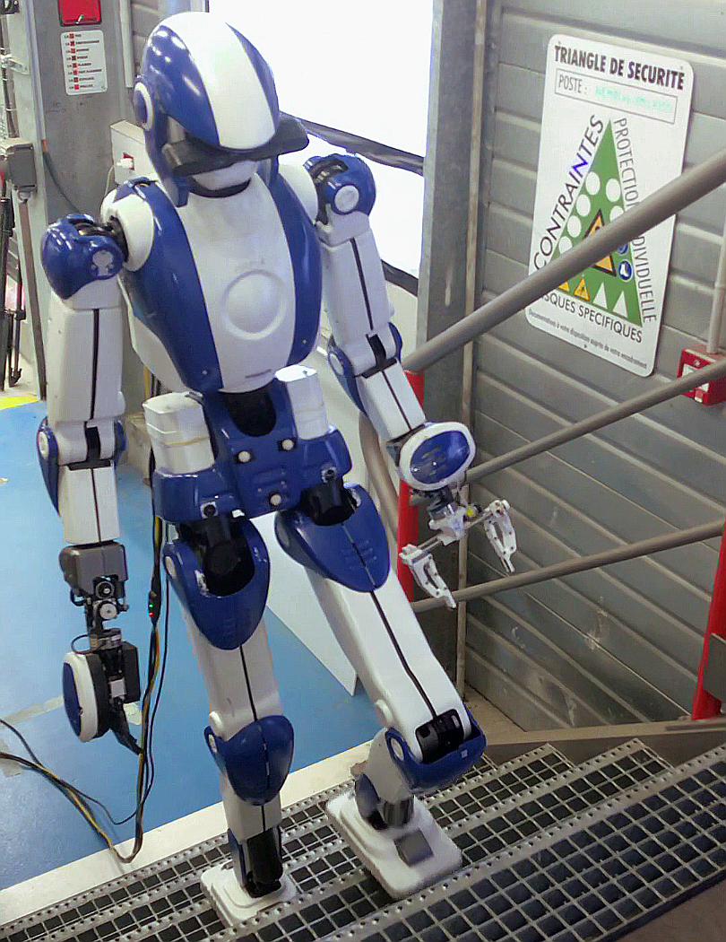
We consider dynamic stair climbing with the HRP-4 humanoid robot as part of an Airbus manufacturing use-case demonstrator. We share experimental knowledge gathered so as to achieve this task, which HRP-4 had never been challenged to before. In particular, we extend walking stabilization based on linear inverted pendulum tracking [1] by quadratic programming-based wrench distribution and a whole-body admittance controller that applies both end-effector and CoM strategies. While existing stabilizers tend to use either one or the other, our experience suggests that the combination of these two approaches improves tracking performance. We demonstrate this solution in an on-site experiment where HRP-4 climbs an industrial staircase with 18.5 cm high steps, and release our walking controller as open source software.111https://github.com/stephane-caron/lipm_walking_controller/
I Introduction
Recently, humanoid robotics has reached a level of maturity that allows considering deployments in large-scale manufacturing (e.g. aircraft and shipyard), construction sites and nuclear power plants. These environments are populated with stairs. In the case of aircraft manufacturing and shipyards, they allow workers to travel between different shop-floor levels where assembly tasks are required, which makes them a key challenge for any mobile robotics application. Stair climbing was demonstrated as early as the first release of the Honda humanoid robot in 1997 [2], yet it is still a challenging task that humanoids rarely perform untethered. Robust stabilization is a critical issue, not only to prevent robot falls, but for the safety of human co-workers that are present and share the same working space222Performance and safety certification requirements are yet to be defined.
In order to correct the deviation of their floating base from a reference pattern, position-controlled robots adjust their contact forces with the environment via admittance control. To the exception of Honda humanoid robots333Controllers reported by Honda include the model ZMP control strategy [2, 3] where saturation of ZMP constraints triggers recovery CoM accelerations and a corresponding update of the walking pattern [4, 5]. This integration of a switching control law with replanning behavior makes these controllers more advanced than linear feedback controllers., controllers found in the literature implement admittance either at the level of end-effectors [1, 6, 7, 8] or at the level of the CoM [9, 10, 11, 12]. Yet, these two strategies are not mutually exclusive. In this work, we investigate a whole-body admittance controller where both end-effector and CoM strategies are applied simultaneously. Preliminary analysis in stair climbing simulations and experiments suggests that a combination of these two approaches can improve tracking performance.
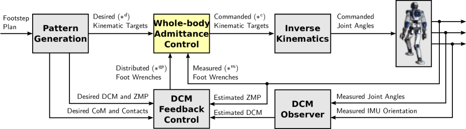
Figure 2 illustrates the components implemented in our walking and stair climbing controller. The two main components for stabilization are:
We illustrate the performance of this controller in an on-site experiment in the Airbus Saint-Nazaire site where the HRP-4 humanoid climbs a staircase with 18.5 cm steps. To the best of our knowledge, this is the first time that dynamic stair climbing is demonstrated with HRP-4. The controller used in this experiment is also open source and open to comments.1
II DCM Feedback Control
The goal of this first component is to regulate the robot’s first-order dynamics assuming control of its second-order dynamics. This amounts to decide a net contact wrench that compensates deviations from the walking pattern.
Within the equations of motion of an articulated robot [13], the centroidal dynamics is governed by the Newton-Euler equation:
| (1) |
where denotes the total robot mass, is the gravity vector, the position of the center of mass (CoM) and the angular momentum around . The net contact wrench consists of the resultant of external contact forces applied to the robot and their moment around . The left-hand side of this equation corresponds to the net motion of the robot, while the right-hand side represents its interaction with the environment. The gist of locomotion is to leverage these interaction forces to move the CoM (or similarly the translation of the floating base) to a desired location.
II-A Linear Inverted Pendulum Mode
A general walking pattern generator [14] can provide both a CoM trajectory and an angular-momentum trajectory . Alternatively, this output can be reduced to the single CoM trajectory by considering solutions where . The resulting model, known as the Inverted Pendulum Mode (IPM) [15], is expressive enough for walking or stair climbing. It simplifies eq. (1) to:
| (2) |
where the contact wrench is now characterized by a scaling factor and a zero-tilting moment point (ZMP) .
Another working assumption acceptable for walking over a horizontal surface is that of a constant CoM height above that surface. This gives rise to the Linear Inverted Pendulum Mode (LIPM) [16]:
| (3) |
where , and we drop from now on the gravity vector by considering only horizontal coordinates. The LIPM linearizes the dynamics (2) of the IPM by turning the variable into a constant. Its contact wrench is characterized by the position of the ZMP on the contact surface.
These simplifications come at the expense of balance recovery strategies: the IPM sacrifices the hip strategy [17] while the LIPM sacrifices the height-variation strategy [18, 19]. Accordingly, the dimension of the contact wrench decreases from six to three in the IPM and two in the LIPM. A LIPM-based stabilizer such as the one reported in the present paper can leverage these two force coordinates to control two position coordinates, for instance the horizontal position of the center of mass [1] or equivalently the rolling and pitching angles of the floating base [3].
II-B Feedback of the Divergent Component of Motion
The divergent component of motion (DCM) of the LIPM is defined by . It allows a decomposition of the second-order eq. (3) into two coupled first-order systems [4]:
| (4) | ||||
| (5) |
While the DCM naturally diverges away from the ZMP by eq. (4), eq. (5) shows that the CoM is guaranteed to converge to the DCM without being controlled. It is therefore sufficient for locomotion to control only the DCM, rather than e.g. both the CoM position and velocity.
Walking pattern generation provides a trajectory in the linear inverted pendulum mode (3), from which one can derive and . The DCM can be controlled around this reference by proportional feedback [20, 21, 22]:
| (6) |
where is a positive feedback gain and the superscript denotes estimated quantities.
An integral term can be added to eliminate steady-state error [7], which would correspond here to an offset between the CoM and ZMP positions when the robot is in static equilibrium:
| (7) |
The integral term can include an anti-windup strategy such as saturation. We used an exponential moving average, also known as leaky integrator:
| (8) |
where is the integrator time constant. This average does not wind up by construction, and its implementation takes a single floating-point number in memory.
Finally, a derivative term can be added to damp potential oscillations. From eq. (4), it can be implemented indifferently by adding or substracting to the commanded . We choose the latter in what follows.
From eq. (4), DCM feedback control can then be written in terms of the commanded ZMP:
Note that the fact that the commanded and measured appear on both sides of this equation comes from the unmodeled delay of admittance control.444DCM feedback gains can be chosen by pole placement based on an estimate of this delay [1, 7]. This commanded ZMP is equivalent to a commanded net contact wrench:
| (9) |
Thus, DCM feedback is a way to determine a net contact wrench that includes both a feedforward term from the walking pattern and a feedback term to correct CoM position and velocity deviations from their reference.
II-C Contact Wrench Distribution
While stabilizers based on CoM admittance control [9, 11, 12, 23] take the net wrench as only input, those that include foot force control need to distribute this wrench among contacts. This operation corresponds to the ZMP distributor of the stabilizer by Kajita et al. [1]. Meanwhile, the net wrench obtained by DCM feedback is saturated in order to account for feasibility constraints such as keeping the ZMP inside its support area. Both distribution and saturation operations can be handled at once by formulating the wrench distribution problem as a quadratic program (QP).
We will make use of spatial vector algebra [24] to describe this program. Let us denote by the net contact wrench coordinates from eq. (9) expressed in the inertial frame 0. Define and the left foot contact wrench expressed respectively in the left sole center frame lc and ankle frame la (sole frame closest to the ankle joint). Wrenches and are defined similarly.
II-C1 Constraints
in double support, the wrench distribution QP consists of two constraints: contact stability, and a minimum pressure at each contact:
| (10) | ||||||
| (11) |
where is the matrix of the contact wrench cone [25]. This matrix includes all three components of the contact-stability condition: the Coulomb force friction cone, center-of-pressure support area and net yaw moment boundaries. Meanwhile, is the basis vector that selects the resultant pressure of a wrench, and is a small threshold such as N. This constraint avoids sending low-pressure targets to the foot force controller, as fixed-gain admittance control tends to oscillate around contact switches for such targets.
II-C2 Costs
the cost function of the wrench distribution QP weighs three objectives:
| (12) | ||||
| (13) | ||||
| (14) |
First and foremost, the solution should realize the net contact wrench as close as possible (12). Second, it should minimize ankles torques (13), where is a diagonal weight matrix with for ankle torques and a small value for all other components. Finally, the pressure ratio should be as close as possible (14) to a prescribed value . This last term regularizes the discontinuity in force output that occurs in acceleration-based whole-body controllers when adding or removing contacts [26, 8]. The prescribed pressure ratio ranges from at the beginning of the double support phase to at the end of it.
Although we presented and implemented it as a quadratic program, this optimization is in essence a lexicographic optimization [27] whose four levels are (10)–(11), (12), (13) and (14). We approximate this behavior by setting cost weights to for (12), for (13) and for (14). Note that the latter two costs are omitted during single support where there is no force redundancy and the net-wrench cost (12) is enough to define a single optimum.
III Whole-body admittance control
Whole-body admittance control implements feedback control of the desired force targets issued by DCM feedback and wrench distribution, while otherwise following the position targets prescribed by the walking pattern.
III-A Foot damping control
Admittance control applied at the ankle joint has been referred to as ground reaction force control [2, 3], foot damping control [1], or foot adjusting control [11]. It implements the first stabilization strategy from Section 4.5.1 of the Introduction to Humanoid Robotics [28].
Let us denote by the commanded (see Figure 2) roll and pitch angles of the ankle joint of a foot in contact with the environment. We apply the following damping control law555Damping control is a shorthand for first-order admittance control. to track a desired CoP:
| (15) | ||||
| (16) |
where denotes the target CoP position in the foot frame provided by the wrench distribution QP, and is the measured contact wrench expressed at the origin of the foot frame. The matrix of admittance gains is used to tune the responsiveness of the task: a higher implies that the foot will roll faster in reaction to lateral CoP deviations, and similarly a higher implies that the foot will pitch faster in reaction to sagittal CoP deviations. We further clamped the absolute values of the resulting velocities to rad/s.
The above eq. (15) is adapted from [1], with the slight difference that we track the desired CoP rather than a desired torque. The two approaches are equivalent under accurate foot pressure difference tracking, but in situations where the latter is degraded, the CoP formulation naturally defines the pressure-dependent admittance coefficients identified in [29]. This task can be extended to include integral and derivative terms of the measured wrench [8]. It may also be improved by a model of the flexibility located between the ankle joint and foot sole [3, 30], which we do not include.
III-B Foot force difference control
In a walking gait, double support phases are used to transfer the net ZMP from one support foot to the next. It is therefore helpful to servo not only the CoP targets provided at each foot, but also their pressure. For this purpose, Kajita et al. [1, 31] introduced foot force difference control (FFDC). Denoting by the respective velocities of the left and right foot in their sole frames, FFDC can be implemented as:
| (17) | ||||
| (18) | ||||
| (19) | ||||
| (20) |
The velocity term implements a damping control that lifts the foot in excess of pressure and lowers the other one. It is tuned by the admittance gain . The second velocity term is added for vertical drift compensation. It retrieves the same average foot altitude as in the walking pattern, tuned by a frequency gain set to Hz in practice. This choice of a velocity formulation (17)–(20) of FFDC rather than the position one from [1] is contingent to our inverse kinematics and yields the same behavior.
An implicit side effect of FFDC is that it increases CoM compliance. To illustrate this remark, consider the example of a constant external push applied to laterally: with only foot damping control, the robot will resist it by tilting its feet, while with FFDC it will lift the leg opposite to the push, resulting (as gravity maintains contact) in a CoM displacement toward that leg. As such, we may venture to say that our reference controller [1] implicitly included a form of CoM admittance control.
III-C CoM Admittance Control
Admittance control applied at the CoM has been referred to as ZMP compliance control [9], ZMP damping control [11], position-based ZMP control [12] or horizontal compliance control [23]. It implements the third stabilization strategy from Section 4.5.1 of the Introduction to Humanoid Robotics [28], and should not be confused with the model ZMP control (fifth strategy) applied on Honda robots [2, 3, 5]. The former adds CoM accelerations at all times, the latter only upon saturation of a ZMP constraint.
We apply the following admittance control law:
| (21) | ||||
| (22) |
where is the feedforward CoM acceleration from the walking pattern, is the ZMP of the measured net contact wrench and is the ZMP of the net contact wrench output by the distribution QP (Section II-C). The matrix of admittance gains is used to tune the responsiveness of the task: the higher the gain, the faster the CoM will accelerate toward the measured ZMP so as to move it back towards the desired one.
Figure 3 shows a simulation example of step climbing without and with CoM admittance control, both foot damping control laws being active. The CoM admittance law does not seem to conflict with the end-effector ones. On the contrary, it improves both DCM and ZMP tracking noticeably.
III-D Inverse Kinematics
Commanded velocities and accelerations are sent to a weighted task-based inverse kinematics solver [8, 26]. The following tasks are considered simultaneously:
-
•
Maintain foot contact(s) (weight: 10000)
-
•
CoM position and velocity tracking (weight: 1000)
-
•
Swing foot position and velocity tracking (weight: 500)
-
•
Bend the chest to a prescribed angle (weight: 100)
-
•
Keep the pelvis upright (weight: 10)
-
•
Regularizing half-sitting joint configuration (weight: 10)
Each task implements an acceleration-based tracking law:
| (23) |
Task damping coefficients are set by default to their critical value , with the exception of foot contact tasks where we use Hz and Hz2. In single support where foot force difference control is disabled, the translation stiffness of the support foot task is increased to Hz2 for vertical drift compensation.
For a foot in contact, the target velocity of the corresponding foot contact task is defined from eq. (15) and (17)–(18). At present, we kept and fixed to the desired contact location. For an improved behavior, the latter can be updated by an integral of the so that all targets become consistent [8].
IV Experiments
We implemented our controller in the mc_rtc framework (see the Appendix for details on other components) and carried out experiments with the HRP-4 humanoid robot [32].
IV-A Demonstration environment
Experiments were carried out on-site at the Airbus factory located in Saint-Nazaire, France. In the final demonstration, the robot walked to the staircase, climbed it, walked to a designated area inside the fuselage of an A350 aircraft and performed an assembly task before walking out. The staircase climbed to access the assembly area had five steps of length cm and height cm.
In preliminary experiments with varying step heights, shown in the accompanying video,666https://www.youtube.com/watch?v=vFCFKAunsYM we also used a cable-driven parallel robot to act as safety crane for HRP-4. This robot was developed in our laboratory and consists of eight actuators, four of which were used. Cables were attached to a taylored holder connecting safety ropes to the shoulders of the humanoid. The system was remote-controlled by a human operator, making sure that the ropes stay loose while trying to avoid hitting the robot as it climbs (bonus robustness checks otherwise).
IV-B Results
We confirmed that HRP-4 can dynamically climb the industrial staircase, as shown in Figure 1 and in the accompanying video. The performance was reproduced time and again over the course of two weeks spent on-site at the Airbus site, and deemed robust enough to let the robot climb without safety ropes in the latter experiments. The robot climbs the stairs in 18 s with 1.4 s single-support and 0.2 s double-support durations. DCM feedback was tuned as follows:
| [Hz] | [Hz] | [Hz] | [s] |
| 5 | 20 | 2 | 20 |
Meanwhile, admittance control parameters were set to the following values (in [s.kg-1] and [kg-1] respectively):
| 0.01 | 0.01 | 0.0001 | 20 | 10 |
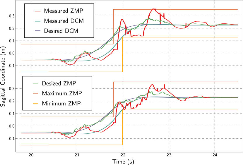
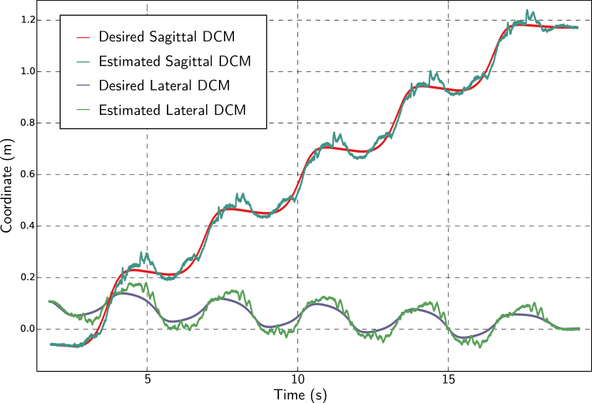
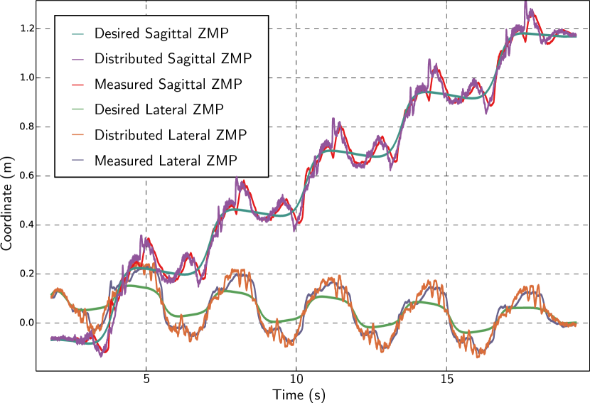
DCM and ZMP tracking performance are reported in Figure 4 and 5 respectively.
The overall run time of a controller cycle on a consumer laptop computer is around ms, which fits within the ms of HRP-4’s control loop. Most of this time is spent solving the inverse kinematics QP ( ms) and the wrench distribution QP ( ms during double support) using the LSSOL least-squares solver for both. Running at a lower frequency, the model predictive control QP is solved in ms using the QLD solver.
To avoid collisions, the apex of swing foot trajectories for each step is set to 24 cm, which is a first source of DCM disturbance. The second main cause are the CoM height variations at each step that disturb the horizontal ZMP backwards. We mitigated this by delaying CoM lift to the end of the step, unfortunately thus increasing knee torques as well. A better way to improve this in future work will be to switch to a pattern generation method taking height variations into account [19, 21, 33].
IV-C Practicalities
One of the most precious tools at our disposal during our trials and errors was the Choreonoid environment and its dynamics simulator [34], in which we could reproduce most of the phenomena encountered in practice. The ability to test controllers in fast simulations rather than slow experiments is a serious enabler, and for humanoid robotics, Choreonoid outperformed alternatives like V-REP or Gazebo in terms of both realism and real-time performance.
During our first experiments, the robot would systematically servo-off during the second (most knee-torque intensive) swing phase of step climbing. This was caused by a drop of voltage due to a maximum current setting of 5 A on the power supply. We increased this threshold and observed peak current draws reaching up to 13 A. We estimate the peak power consumption to be around 750 W. For comparison, ASIMO consumes 600–900 W when its servomotors are turned on, and around 1000 W during stair climbing [35]. The consumption gap between the two robots is mostly owed to the design of HRP-4 [32], which is both lighter (40 kg versus 50 kg) and taller than its Honda sibling (1.5 m versus 1.3 m), allowing it to bend its knees less while climbing.
Our initial plan was to climb (i) a single step, then (ii) the staircase with double-support phases at each step, and finally (iii) a more human-like stair climbing with exactly one foot contact per step. We presently report on (ii) but not (iii), as a mechanical transmission issue prevents our robot from performing with its right leg the motions that it achieves with the left one, even for lower step heights.
V Related stair climbing works
Stair climbing for bipeds with ZMP-based stabilizers started as early as 1993, when the Honda E6 prototype climbed staircases thanks to the stabilization strategies developed by Takenaka [35]. This method was showcased in 1997 for the public release of the P2 humanoid robot [2]. Stair climbing was also demonstrated in 2002 on the prototype HRP-1S of the HRP series [11].
However, the stabilizer component provided with robots of the HRP series is mainly designed for walking on overall level ground. Climbing over small staircases with 10 cm steps has been reported on HRP-2 [14, 36], walking with bent knees to avoid undesired behavior close to the knee kinematic singularity. In [6], KHR-2 climbed stairs with 12 cm steps. In [14], HRP-2 also climbed stairs with 15 cm steps while grabbing a handrail.
Step heights above 20 cm have been demonstrated, yet with slower gaits. In [37], HRP-4 climbed a 24 cm step, but without stabilization and with a quasi-static motion lasting more than 80 s. During the DARPA Robotics Challenge, six teams successfully climbed a staircase with four 23 cm steps, yet with slow motions and doing frequent pauses as a result of the challenge’s conditions. Shank collisions also become a concerning problem for higher step heights. To deal with this issue, team KAIST climbed stairs backwards [38] while teams IHMC and ESCHER used partial footholds [39, 22].
VI Conclusion
In this paper, we reported on the state-of-the-art of walking stabilization by DCM feedback control and suggested two improvements: a wrench distribution quadratic program, and a whole-body admittance controller combining both end-effector and CoM strategies. We applied the resulting controller in a dynamic stair climbing experiment over 18.5 cm steps, performed in an industrial environment at the Airbus Saint-Nazaire site.
Our stabilizer has a number of gains to tune, some of which interact with each other. For instance, lowering foot CoP admittances allows one to raise the DCM feedback gain to larger values before reaching the unstable regime. The elephant in the room hindering our understanding here is the unmodeled flexibility below foot ankles, modeled as a first-order ZMP delay in [1, 7]. Future work will require us to investigate this question, and at least another one: how to prevent or mitigate touchdown impacts?
Acknowledgments
The authors warmly thank Kevin Chappellet for his help with robot hardware, Pierre Gergondet for developing mc_rtc, Daniele De Simone and Arnaud Tanguy for their assistance with experiments, Tomomichi Sugihara and Pierre-Brice Wieber for helpful and friendly discussions, as well as Junhyeok Ahn, Andrea Del Prete and Louise Scherrer for their feedback. The cable-driven parallel robot used during preliminary experiments was realized thanks to the support of the European Union through FEDER Grant No 49793.
-A Walking Pattern Generation
We generate walking patterns by linear model predictive control [40] over pre-defined footstep locations. The corresponding QP minimizes three weighted costs:
-
•
ZMP deviation from a reference (weight: 1000)
-
•
CoM velocity deviation from a reference (weight: 10)
-
•
CoM jerk (weight: 1)
The reference ZMP trajectory consists of straight lines connecting foot ankle frames. The QP also enforces the following three constraints:
-
•
Feasibility: ZMPs lie in their support polygons
-
•
Terminal constraint 1: the ZMP ends on
-
•
Terminal constraint 2: the DCM ends on
where s is the duration of the predictive horizon and the sampling period is set to ms. We let predictive control update the CoM reference and its derivatives by open-loop integration rather than a closed-loop approach [41].
-B DCM observer
Although we plan to evaluate methods that take into account foot flexibilities [42, 43], for now we use a simple kinematics estimator based on Kalman filtering to estimate the orientation of the floating-base and an anchor-point assumption to estimate its translation. The CoM position is then derived by forward kinematics of joint-encoder readings, and its velocity by low-pass filtering.
References
- [1] S. Kajita, M. Morisawa, K. Miura, S. Nakaoka, K. Harada, K. Kaneko, F. Kanehiro, and K. Yokoi, “Biped walking stabilization based on linear inverted pendulum tracking,” in IEEE/RSJ International Conference on Intelligent Robots and Systems, 2010.
- [2] K. Hirai, M. Hirose, Y. Haikawa, and T. Takenaka, “The development of honda humanoid robot,” in International Conference on Robotics & Automation, 1998.
- [3] T. Takenaka, T. Matsumoto, and T. Yoshiike, “Real time motion generation and control for biped robot-4th report: Integrated balance control,” in IEEE/RSJ International Conference on Intelligent Robots and Systems, 2009.
- [4] ——, “Real time motion generation and control for biped robot-1st report: Walking gait pattern generation,” in IEEE/RSJ International Conference on Intelligent Robots and Systems, Oct. 2009.
- [5] T. Kamioka, H. Kaneko, T. Takenaka, and T. Yoshiike, “Simultaneous optimization of ZMP and footsteps based on the analytical solution of divergent component of motion,” in IEEE International Conference on Robotics and Automation, May 2018.
- [6] J.-Y. Kim, I.-W. Park, and J.-H. Oh, “Realization of dynamic stair climbing for biped humanoid robot using force/torque sensors,” Journal of Intelligent and Robotic Systems, vol. 56, no. 4, 2009.
- [7] M. Morisawa, S. Kajita, F. Kanehiro, K. Kaneko, K. Miura, and K. Yokoi, “Balance control based on capture point error compensation for biped walking on uneven terrain,” in IEEE–RAS International Conference on Humanoid Robots, 2012.
- [8] K. Bouyarmane, K. Chappellet, J. Vaillant, and A. Kheddar, “Quadratic programming for multirobot and task-space force control,” IEEE Transactions on Robotics, vol. 35, no. 1, pp. 64–77, Feb. 2019.
- [9] K. Nagasaka, “Whole-body motion generation for a humanoid robot by dynamics filters,” PhD thesis, 1999, the Univ. of Tokyo, in Japanese.
- [10] T. Sugihara and Y. Nakamura, “Whole-body cooperative balancing of humanoid robot using COG jacobian,” in IEEE/RSJ International Conference on Intelligent Robots and Systems, 2002.
- [11] K. Yokoi, F. Kanehiro, K. Kaneko, S. Kajita, K. Fujiwara, and H. Hirukawa, “Experimental study of humanoid robot HRP-1s,” The International Journal of Robotics Research, vol. 23, no. 4, pp. 351–362, Apr. 2004.
- [12] J. Englsberger and C. Ott, “Integration of vertical COM motion and angular momentum in an extended capture point tracking controller for bipedal walking,” in IEEE–RAS International Conference on Humanoid Robots. IEEE, 2012.
- [13] P.-B. Wieber, “Some comments on the structure of the dynamics of articulated motion,” in Fast motions in biomechanics and robotics, 2006, pp. 411–425.
- [14] J. Carpentier and N. Mansard, “Multi-contact locomotion of legged robots,” IEEE Transactions on Robotics, vol. 34, no. 6, Dec. 2018.
- [15] J. E. Pratt and S. V. Drakunov, “Derivation and application of a conserved orbital energy for the inverted pendulum bipedal walking model,” in IEEE International Conference on Robotics and Automation, May 2007.
- [16] S. Kajita, F. Kanehiro, K. Kaneko, K. Yokoi, and H. Hirukawa, “The 3d linear inverted pendulum mode: A simple modeling for a biped walking pattern generation,” in IEEE/RSJ International Conference on Intelligent Robots and Systems, vol. 1, Sep. 2001.
- [17] B. Stephens, “Humanoid push recovery,” in IEEE–RAS International Conference on Humanoid Robots, Nov. 2007.
- [18] T. Koolen, M. Posa, and R. Tedrake, “Balance control using center of mass height variation: Limitations imposed by unilateral contact,” in IEEE–RAS International Conference on Humanoid Robots, Nov. 2016.
- [19] S. Caron and B. Mallein, “Balance control using both ZMP and COM height variations: A convex boundedness approach,” in IEEE International Conference on Robotics and Automation, May 2018.
- [20] T. Sugihara, “Standing stabilizability and stepping maneuver in planar bipedalism based on the best com-zmp regulator,” in IEEE International Conference on Robotics and Automation, 2009.
- [21] J. Englsberger, C. Ott, and A. Albu-Schäffer, “Three-dimensional bipedal walking control based on divergent component of motion,” IEEE Transactions on Robotics, vol. 31, no. 2, 2015.
- [22] G. Wiedebach, S. Bertrand, T. Wu, L. Fiorio, S. McCrory, R. Griffin, F. Nori, and J. Pratt, “Walking on partial footholds including line contacts with the humanoid robot atlas,” in IEEE-RAS International Conference on Humanoid Robots, Nov. 2016.
- [23] Z. Li, B. Vanderborght, N. G. Tsagarakis, L. Colasanto, and D. G. Caldwell, “Stabilization for the compliant humanoid robot COMAN exploiting intrinsic and controlled compliance,” in IEEE International Conference on Robotics and Automation, 2012.
- [24] R. Featherstone, Rigid body dynamics algorithms. Springer, 2008.
- [25] S. Caron, Q.-C. Pham, and Y. Nakamura, “Stability of surface contacts for humanoid robots: Closed-form formulae of the contact wrench for rectangular support areas,” in IEEE International Conference on Robotics and Automation, May 2015.
- [26] L. Saab, O. E. Ramos, F. Keith, N. Mansard, P. Soueres, and J.-Y. Fourquet, “Dynamic whole-body motion generation under rigid contacts and other unilateral constraints,” IEEE Transactions on Robotics, vol. 29, no. 2, pp. 346–362, Apr. 2013.
- [27] A. Escande, N. Mansard, and P.-B. Wieber, “Hierarchical quadratic programming: Fast online humanoid-robot motion generation,” The International Journal of Robotics Research, vol. 33, no. 7, 2014.
- [28] S. Kajita, H. Hirukawa, K. Harada, and K. Yokoi, Introduction to Humanoid Robotics, ser. Springer Tracts in Advanced Robotics. Springer Berlin Heidelberg, 2014, vol. 101.
- [29] A. Pajon, S. Caron, G. De Magistris, S. Miossec, and A. Kheddar, “Walking on Gravel with Soft Soles using Linear Inverted Pendulum Tracking and Reaction Force Distribution,” in IEEE-RAS International Conference on Humanoid Robots, 2017.
- [30] S. Kajita, K. Yokoi, M. Saigo, and K. Tanie, “Balancing a humanoid robot using backdrive concerned torque control and DIrect angular momentum feedback,” in IEEE International Conference on Robotics and Automation, 2001.
- [31] S. Kajita, F. Asano, M. Morisawa, K. Miura, K. Kaneko, F. Kanehiro, and K. Yokoi, “Vertical vibration suppression for a position controlled biped robot.” in IEEE International Conference on Robotics and Automation, 2013.
- [32] K. Kaneko, F. Kanehiro, M. Morisawa, K. Akachi, G. Miyamori, A. Hayashi, and N. Kanehira, “Humanoid robot HRP-4 - humanoid robotics platform with lightweight and slim body,” in IEEE/RSJ International Conference on Intelligent Robots and Systems, Sep. 2011.
- [33] C. Brasseur, A. Sherikov, C. Collette, D. Dimitrov, and P.-B. Wieber, “A robust linear MPC approach to online generation of 3d biped walking motion,” in IEEE–RAS International Conference on Humanoid Robots, 2015.
- [34] S. Nakaoka, S. Hattori, F. Kanehiro, S. Kajita, and H. Hirukawa, “Iterative contact force solver for simulating articulated rigid bodies,” in RSJ 2007, 2007, in Japanese.
- [35] M. Hirose, “The father of the bipedal walking robot ASIMO,” Takeda Foundation Survey Reports, Jun. 2007, in Japanese.
- [36] P. Michel, J. Chestnutt, Satoshi Kagami, Koichi Nishiwaki, James Kuffner, and Takeo Kanade, “GPU-accelerated real-time 3d tracking for humanoid locomotion and stair climbing,” in IEEE/RSJ International Conference on Intelligent Robots and Systems, Oct. 2007.
- [37] T. Zhang, S. Caron, and Y. Nakamura, “Supervoxel plane segmentation and multi-contact motion generation for humanoid stair climbing,” International Journal of Humanoid Robotics, vol. 14, Mar. 2017.
- [38] J. Lim, I. Lee, I. Shim, H. Jung, H. M. Joe, H. Bae, O. Sim, J. Oh, T. Jung, S. Shin, K. Joo, M. Kim, K. Lee, Y. Bok, D.-G. Choi, B. Cho, S. Kim, J. Heo, I. Kim, J. Lee, I. S. Kwon, and J.-H. Oh, “Robot system of DRC-HUBO+ and control strategy of team KAIST in DARPA robotics challenge finals,” Journal of Field Robotics, 2016.
- [39] M. A. Hopkins, R. J. Griffin, A. Leonessa, B. Y. Lattimer, and T. Furukawa, “Design of a compliant bipedal walking controller for the DARPA robotics challenge,” in IEEE-RAS International Conference on Humanoid Robots, Nov. 2015.
- [40] P.-B. Wieber, “Trajectory free linear model predictive control for stable walking in the presence of strong perturbations,” in IEEE–RAS International Conference on Humanoid Robots, Nov. 2006.
- [41] N. A. Villa and P.-B. Wieber, “Model predictive control of biped walking with bounded uncertainties,” in IEEE–RAS International Conference on Humanoid Robots, Nov. 2017.
- [42] M. Benallegue, A. Benallegue, and Y. Chitour, “Tilt estimator for 3d non-rigid pendulum based on a tri-axial accelerometer and gyrometer,” in IEEE-RAS International Conference on Humanoid Robots, Nov. 2017.
- [43] T. Flayols, A. Del Prete, P. Wensing, A. Mifsud, M. Benallegue, and O. Stasse, “Experimental evaluation of simple estimators for humanoid robots,” in IEEE-RAS International Conference on Humanoid Robots, Nov. 2017.