Analog MIMO Radio-over-Copper: Prototype and Preliminary Experimental Results
Abstract
Analog Multiple-Input Multiple-Output Radio-over-Copper (A-MIMO-RoC) is an effective all–analog FrontHaul (FH) architecture that exploits any pre-existing Local Area Network (LAN) cabling infrastructure of buildings to distribute Radio-Frequency (RF) signals indoors. A-MIMO-RoC, by leveraging a fully analog implementation, completely avoids any dedicated digital interface by using a transparent end-to-end system, with consequent latency, bandwidth and cost benefits. Usually, LAN cables are exploited mainly in the low-frequency spectrum portion, mostly due to the moderate cable attenuation and crosstalk among twisted-pairs. Unlike current systems based on LAN cables, the key feature of the proposed platform is to exploit more efficiently the huge bandwidth capability offered by LAN cables, that contain 4 twisted-pairs reaching up to 500 MHz bandwidth/pair when the length is below 100 m. Several works proposed numerical simulations that assert the feasibility of employing LAN cables for indoor FH applications up to several hundreds of MHz, but an A-MIMO-RoC experimental evaluation is still missing. Here, we present some preliminary results obtained with an A-MIMO-RoC prototype made by low-cost all-analog/all-passive devices along the signal path. This setup demonstrates experimentally the feasibility of the proposed analog relaying of MIMO RF signals over LAN cables up to 400 MHz, thus enabling an efficient exploitation of the LAN cables transport capabilities for 5G indoor applications.
Index Terms:
C-RAN, Radio-over-Copper, Indoor coverage, 5G.I Introduction
Cloud Radio Access Network (C-RAN) is a very attractive architecture to handle a large number of users and antennas in the same radio resources, as demanded by 5G mobile networks [1]. In particular, C-RAN is enabled by: i) the colocation of BaseBand Units (BBUs) in so-called BBU pools, where centralized processing and interference mitigation are performed; ii) the remote placement of antennas and Radio-Frequency (RF) equipment (Remote Radio Unit, RRU) that are moved away from the BBU and geographically distributed both indoors and outdoors close to the end-users. This allows for centralized signal processing, network scalability, increased spectral efficiency and costs reduction [2]. C-RAN is already deployed in current (4G) mobile networks, in which BBUs and RRUs exchange digital In-phase and Quadrature (I/Q) signals over the so-called FrontHaul (FH) link according to any of the routinely employed communication protocols e.g., the Common Public Radio Interface (CPRI) [3]. However, the massive number of antennas and the increase in radio signal bandwidth expected for 5G networks call into question the effectiveness of digital I/Q streaming, which would introduce a bandwidth expansion over the FH link. A viable solution is to completely overtake any signals’ digitization at the RRUs in favor of a fully analog FH where the RRUs up/down-convert and directly relay the analog RF signals to/from the BBU. Analog FH is a promising solution for ultra-low latency applications where latency is ultimately limited to signal propagation, and also enables precise bit/carrier-frequency synchronization among multiple RRUs for MIMO joint processing. [4, 5, 6, 7].
In this context, C-RAN with analog FH based on Local Area Network (LAN) cables, namely Analog Radio-over-Copper (A-RoC), has been shown to be a cost-effective/bandwidth-efficient solution for upcoming 5G indoor networks [8, 9].
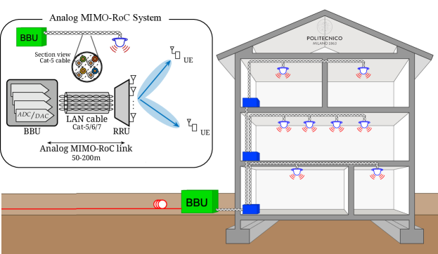
The A-RoC concept has been first proposed for femto-cell systems to exchange analog RF signals between a remote location hosting all PHY/MAC functionalities (BBU) and an in-home antenna device performing only the analog relay of signals (RRU) [4]. Afterwards, A-RoC gained lots of attention becoming the basis of commercial solutions exploiting the pre-existing LAN cables of buildings to extend indoor coverage over distances longer than 100 m [5]. By using all 4 twisted-pairs contained into the LAN cable at low-frequency (characterized by low attenuation and crosstalk interference), one can serve up to 4 antennas (e.g., 4x4 MIMO) per LAN cable. An A-RoC architecture for LTE signals, referred to as LTE-over-Copper, has been proposed in [10] and references herein, showing the capability to relay 3GPP-compliant LTE signals in the 21-24 MHz cable frequency band.
Although demonstrating the feasibility of the A-RoC architecture, the aforementioned works consider only the low-frequency portion of copper-cables, i.e., 0-120 MHz, due to low cable attenuation and crosstalk among twisted-pairs, thus not fully exploiting the transport capability of LAN cables. In this direction, A-RoC has been recently extended to the so-called A-MIMO-RoC architecture (see Fig. 1), precisely with the goal to make a more efficient usage of the large bandwidth offered by the 4 twisted-pairs contained into a single LAN cable, providing up to 500 MHz bandwidth/pair (2 GHz bandwidth overall) [8, 11, 12, 13, 14, 15]. Simulation results demonstrated that, in principle, a single 100-m Cat-6 LAN cable is capable to serve up to 60 RRU antennas each carrying a 20-MHz LTE signal, achieving up to 10 Gbps equivalent wireless data-rate [8]. However, it has been demonstrated that in order to achieve this performance figure, it is needed to define an opportune low-complexity/all-analog mapping of the RF signals at the RRU antennas onto a combination of twisted-pairs/frequency channels over the cable. This wired-wireless resource allocation strategy, denoted as Space-Frequency to Space-Frequency (SF2SF) multiplexing, has been shown to minimize interference among signals carried over different twisted-pairs, hence enabling an efficient usage of the LAN cable bandwidth [13, 11, 12, 14]. An alternative formulation/solution to the RoC wired-wireless resource scheduling problem has been recently presented for 4G systems [16], and then extended to 5G New Radio (NR) indoor architectures [17, 18].
Previous works [8, 11, 12, 13, 14, 15] proved the effectiveness of A-MIMO-RoC in terms of equivalent wireless capacity by numerical analysis, however, an experimental validation of the A-MIMO-RoC architecture is still missing, and this is the focus of this paper. It is worth mentioning that the proposed A-MIMO-RoC platform is also suitable in antenna remotization scenarios for indoor WLAN applications where the cost of CPRI interfaces cannot be afforded.
Contribution
This paper presents preliminary experimental results demonstrating the potential of A-MIMO-RoC as an effective architecture for perspective 5G indoor networks. A prototype has been purposely developed in order to evaluate the performance of A-MIMO-RoC whereby multiple LTE signals are carried over the same LAN cable at high cable frequency, i.e., impaired by severe intra-cable crosstalk and cable attenuation [8]. In particular, experiments demonstrate the feasibility of transporting, in an all-analog fashion, multiple MIMO LTE signals over a single multi-pair copper-cable up to 400 MHz cable frequency with negligible performance degradation. This enables a more efficient exploitation of LAN cables transport capabilities, which are thus proved to offer enough bandwidth for indoor applications. To this aim, the TRIANGLE testbed [19, 20] played a key role in measuring the end-to-end performance degradation introduced by the proposed A-MIMO-RoC architecture.
Organization
The paper is organized as follows: Sect. II introduces the TRIANGLE testbed used for the experiments, while the setup for testing the A-MIMO-RoC platform is in Sect. III. Sect. IV shows some preliminary experimental results. Sect. V draws some preliminary conclusions and highlights future research directions.
II The TRIANGLE Testbed
The TRIANGLE testbed is the main core of the H2020 TRIANGLE project [20], whose objective is to promote the testing and benchmarking of 5G mobile applications and User Equipments (UEs). In particular, the TRIANGLE testbed allows to run multiple tests in a controlled environment that encompasses all elements of the telecommunication chain, from radio signal generation to the end-to-end testing of mobile applications. An extensive description of the TRIANGLE testbed is outside the scope of this paper. Details can be found in [19, 20], while here we review only the main elements that have been employed for the A-MIMO-RoC testing.
II-A Keysight UXM RAN Emulator
The UXM Wireless Test Platform by Keysight Technologies allows to emulate multiple cellular networks in a controlled manner by supporting multiple Radio Access Technologies (multi-RAT), including GSM/GPRS, UMTS and LTE-Advanced networks (i.e., 2G, 3G, 4G and 4.5G). UXM features include intra- and inter-RAT handovers, protocol debugging, IP end-to-end delay, BLock Error Rate (BLER) and throughput measurements, in addition to the possibility of performing RF conformance tests. The UXM device offers great customization capabilities and an intuitive user interface, which allow to easily evaluate the Key Performance Indicators (KPIs) of interest under any possible system setting defined by the 3GPP. Moreover, the UXM device features an advanced fading engine with the main channels models defined by 3GPP [21]. The UXM device has been employed to generate the MIMO LTE radio signals and to emulate specific propagating channel conditions, e.g., the ETSI Pedestrian at 5 Hz (EPA5) channel model, which fairly describes the typical indoor office scenario targeted by the A-MIMO-RoC system.
II-B Mobile Device Monitoring
In order to measure the KPIs perceived by the end-device, some additional tools, detailed below, are needed on the smartphones under test, i.e., the UE, according to the scenario in Fig. 2.
II-B1 Performance Tool
In order to guarantee high resolution reporting of the target QoS KPIs, especially in 5G scenarios, the DEKRA Performance Tool has been integrated into the TRIANGLE testbed [22]. Beside providing accurate one-way measurements, the DEKRA Performance Tool tool includes a built-in traffic generator and enables the automation and testing of Android mobile Apps by measuring relevant Quality of Experience (QoE) KPI. In particular, the DEKRA Performance Tool was employed to perform end-to-end YouTube application testing, which allowed us to quantify the performance degradation introduced by the relaying over LAN cable in terms of YouTube video streaming quality. However, these results have not been reported here for brevity.
II-B2 TestelDroid Mobile Monitoring App
TestelDroid is a software tool developed by the University of Malaga (UMA) [23] that enables passive monitoring of radio parameters and data traffic in Android-based devices. Logging is implemented as an Android service that can be running in the background logging all information while running the application under test, e.g., YouTube. This functionality enables monitoring of traffic information generated by any application, which extends the testing to a very wide range of use cases. The logged parameters (neighbor cells, GPS, traffic, etc.) can be flexibly configured.
III A-MIMO-RoC Experiment Setup
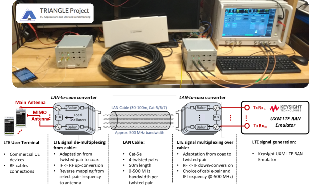
To test the A-MIMO-RoC platform, we used the TRIANGLE testbed in the typical device-testing configuration [20], but inserting a 4-pairs RJ45 Cat-5e LAN cable between the RF output ports of the UXM and the RF connections at the UE (see Fig. 2) to evaluate experimentally the performance degradation due to the all-analog RF-to-RF relaying of signals over copper. As shown in Fig. 2, the RF signals from the UXM are transported by two LAN-to-Coax Converters (L2CCs) to the remote antennas and then to the UEs. For lack of space, a detailed circuit description of the two converters, that represent the core of the A-MIMO-RoC platform, is omitted here. L2CCs are two identical devices connected back-to-back through the RJ45 LAN cable. The L2CC on the right of Fig. 2 performs impedance adaptation, RF down-conversion, Intermediate-Frequency (IF) mapping and IF cable equalization to convert the RF signals into their IF counterparts to feed the 4 twisted-pairs cables. The L2CC on the left performs the inverse operations on the IF signals: cable equalization, IF demapping, RF up-conversion and impedance adaptation to recover the RF signals. The passive cable equalization circuit, designed for 50-m and 100-m LAN cables, is split between both L2CCs, while adaptive active equalization is envisioned for a future version of the prototype. Both L2CCs include only low-cost/complexity all-passive all-analog devices along the signal path in order to perform fully bi-directional transparent operations, e.g., for Time Division Duplexing (TDD) systems. For all wireless communication trials with the A-MIMO-RoC platform, we used a 50-m long Cat-5e LAN cable, commonly deployed in buildings, with a cable bandwidth tested here up to 400 MHz/pair.
The experimental setup is represented in Fig. 2, together with a simplified block diagram detailing the role of each of the components used for the experiments (i.e., RAN Emulator, L2CCs, LAN cables and UE). In details, the experiment setup is as follows (only the downlink is described, uplink symmetrical): (i) up to 4 RF LTE signals are generated by the UXM; (ii) RF cables are connected at each RF output ports of the UXM; (iii) the signal carried on each RF cable is down-converted to IF to match the bandwidth over the LAN cable, e.g., in the 10-400 MHz frequency range, possibly multiplexed in frequency over cable by the first L2CC; (iv) each IF-converted signal is conveyed by one of the 4 twisted-pairs: cable adaptation/equalization, coax-to-pairs mapping and RF/IF down-conversion between coax and twisted-pair is performed by the L2CC; (v) at the other end of the LAN cable, the second L2CC performs cable adaptation/equalization, pairs-to-coax de-mapping and IF/RF up-conversion to interface with the UE under test by using RF cables; (vi) DEKRA Performance Tool and TestelDroid, integrated into the TRIANGLE testbed, are used to test the UEs.
IV Experimental Results
The focus of this experiment was to demonstrate the viability of remotizing RF antennas by relaying multiple LTE signals over the same 50-m Cat-5e LAN cable and to evaluate the end-to-end performance degradation introduced by the cable. It is well known that the low-frequency spectrum of LAN cables is suitable for transmission due to the mild crosstalk among pairs and cable attenuation (see [8] for typical LAN cables characteristics). However, in order to enable a more efficient usage of the LAN cable bandwidth, our goal is to prove that also the more challenging high-frequency spectrum of LAN cables can be exploited for the analog FH transmission.
![[Uncaptioned image]](/html/1809.05363/assets/x3.png)
In particular, we tested the relaying over copper-cable of a MIMO LTE signal using the LTE system settings parameters reported in Table I. Performance have been evaluated in the DownLink (DL) direction in terms of throughput and BLER for different Modulation and Coding Schemes (MCS) values, ranging from 0 (0-QPSK) to 17 (17-16QAM) [24]. In all experiments, we run the tests by keeping fixed each MCS configuration for a duration of minutes. Each measurement point of plots is the average of the given performance metric over 500 ms of test to obtain approx. 240 measurements points for each MCS. Two main experiments, detailed in the following, have been performed for testing the A-MIMO-RoC platform.
IV-A A-MIMO-RoC and cable IF
The goal of this experiment was two-fold: i) to prove the feasibility of transporting the 2 RF bands, corresponding to the 2 MIMO ports, over 2 different twisted-pairs of the LAN cable but at the same cable IF frequency , where each pair interferes with the other one (see Fig. 3); and ii) to evaluate the performance degradation caused by increasing the value , i.e., to increase the interference among pairs and the attenuation levels [8].
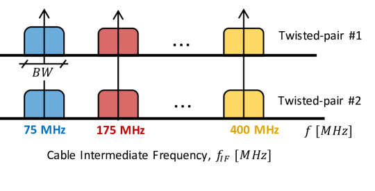
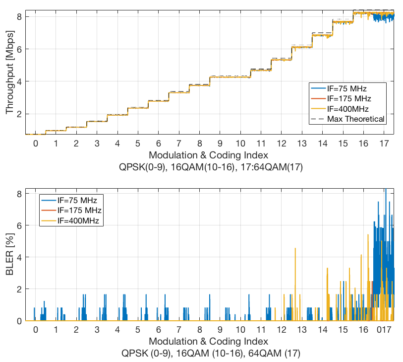
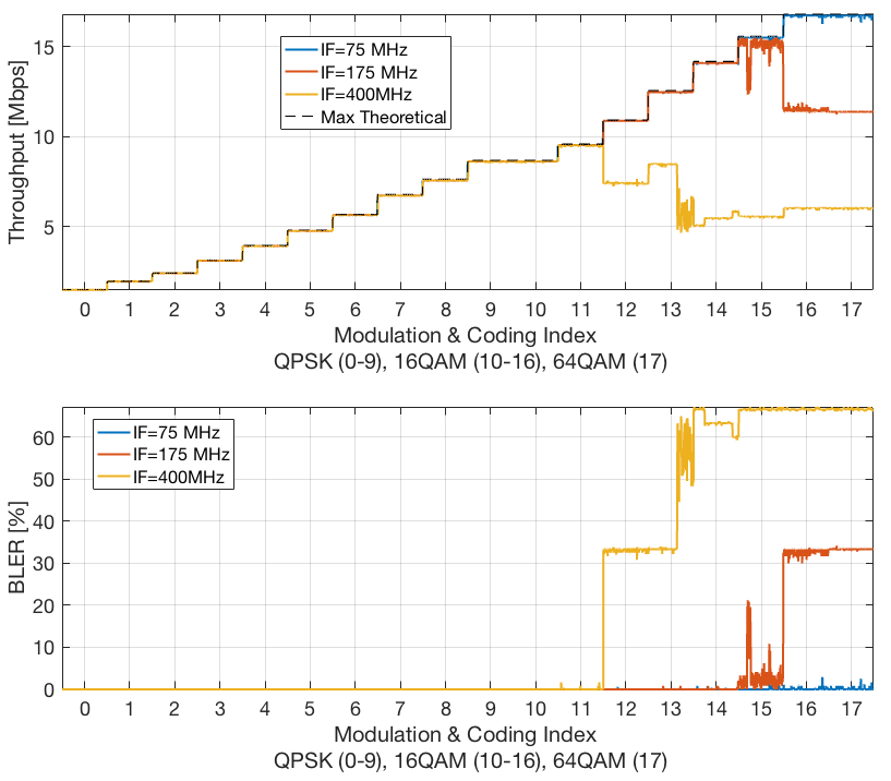
In Fig. 4-5, throughput and BLER are shown considering a Static MIMO channel at -20 dBm/ input power by using three different cable IF values, as shown in Fig. 3: MHz (blue curves), MHz (red curves) and MHz (yellow curves). The maximum theoretical throughput achievable by each MCS [24] (black dashed line) over the considered channel bandwidth () is shown as reference, thus quantifying the performance degradation introduced by the proposed system. For the MHz case, shown in Fig. 4, the loss in terms of throughput introduced by the A-MIMO-RoC setup is almost negligible for all considered MCSs and values. As expected, BLER increases for high MCS, but the degradation with respect to the maximum achievable throughput is still small. However, for MHz shown in Fig. 5, the maximum throughput is achieved for all MCSs only for MHz, while for MHz and MHz the maximum MCS values that can be employed with fairly low BLER are 15-16QAM and 11-16QAM, respectively. This performance degradation, which is more pronounced for higher , is totally expected, and it is explained by the fact that both cable crosstalk and attenuation levels increase with cable frequency [8]. Moreover, the transmit power is the same for both settings, i.e., MHz and MHz (see Table I). Hence, the smaller channel bandwidth, the higher Signal-to-Noise Ratio (SNR) per subcarrier, which explains the better performance obtained in the MHz case. Notice that, as both L2CCs are all-passive and bi-directional devices, signal relaying over cable introduces a significant attenuation (in the order of 60 dB for both L2CCs) which forces the whole system to work close to the UE sensitivity [24], even by setting the transmit power to the maximum value allowed by the hardware devices. It is thus expected that the performance loss observed in case of MHz can be avoided by introducing some signal amplification in the system design, which is left as future works. In any case, Fig. 5 confirms the feasibility of relaying LTE signals over high-frequency copper-cable bands: even in the worst case of 2 LTE bands carried over 2 different twisted-pairs at the same MHz, it is still possible to achieve a throughput of Mbps over MHz. Of course, WLAN indoor scenarios with shorter cables (e.g., length 10-20 m) can fully exploit the transparent antenna remotization capabilities and performances of the A-MIMO-RoC platform.
IV-B A-MIMO-RoC and Channel Models
The goal of this experiment was to evaluate the performance of the A-MIMO-RoC platform for different MIMO channel models. In particular, we adopted the EPA5 channel [21], as it fairly describes the propagating conditions of the indoor office environment targeted by the A-MIMO-RoC platform. We considered a MIMO LTE signal with MHz, where the 2 RF bands were transported over 2 different twisted-pairs at the same frequency MHz. In this experiment, the input power was set to -15 dBm/.
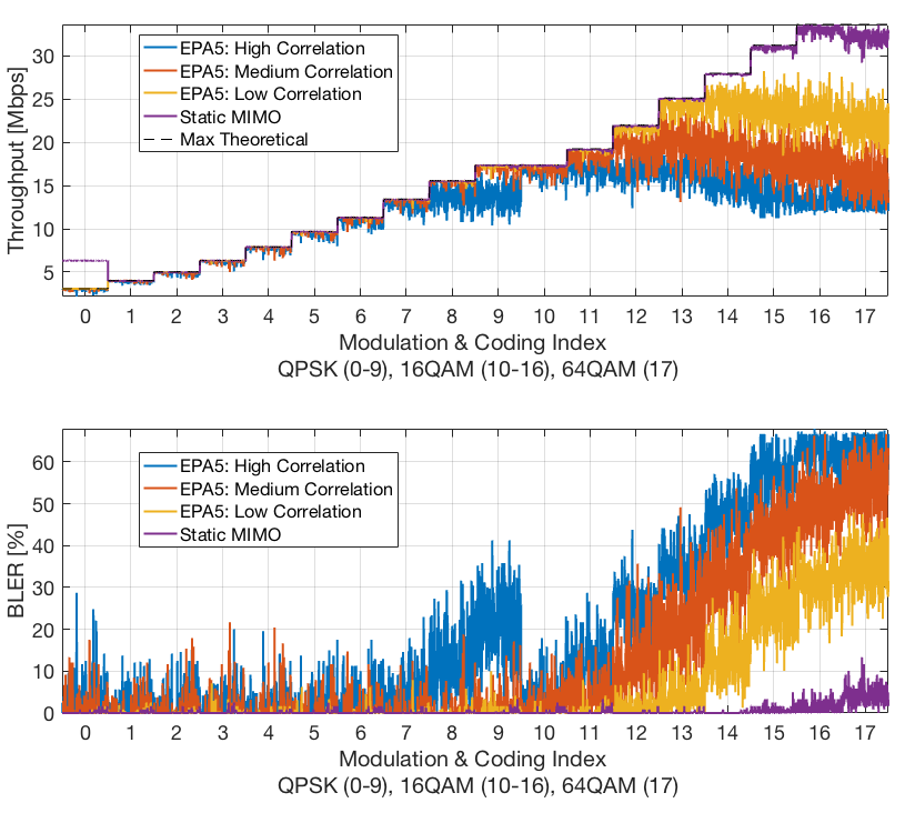
Fig. 6 shows that, in the case of Static MIMO channel, even for MHz, the performance degradation introduced by the cable is negligible (apart from a small loss for high MCS). However, for the EPA5 channel model, performance get worse, especially for medium and high channel correlation and for high MCS. In fact, for practical applications, BLER should be below 10-15%: higher BLER would imply continuous HARQ/ARQ retransmissions leading to unacceptable end-to-end latency, and thus nullifying the latency benefits of the all-analog FH. Accordingly, Fig. 6 shows that for low- and medium-correlated channels, performance for practical applications are limited to 16QAM with Mbps throughput, while they are further reduced to QPSK ( Mbps) for high-correlated MIMO channel. Once again, the reason for this loss relies in the all-passive circuitry implementation of our system, that strongly simplifies the hardware design of the prototype but introduces a significant attenuation. The power fluctuations introduced by the EPA5 channel make the system oscillate around the UE sensitivity threshold for high MCS, which explains the curves’ behavior in the rightmost portion of the figure.
V Concluding Remarks & Future Works
This paper presents some preliminary experimental results asserting the feasibility of the Analog MIMO Radio-over-Copper (A-MIMO-RoC) architecture to transparently relay multiple LTE signals over a single LAN cable in an all-analog fashion, even at high cable frequency. To this aim, an A-MIMO-RoC prototype platform with transparent RF-to-RF capabilities has been purposely developed. The conclusions drawn by the experiments can be summarized as follows: i) LAN cables bandwidth capability can be exploited up to several hundreds of MHz for transparently transporting MIMO Radio-Frequency (RF) signals indoors, even when such signals are transported over different twisted-pairs but at the same Intermediate-Frequency (IF), thus affected by strong cable-crosstalk interference; ii) the performance degradation experienced for high Modulation and Coding Schemes (MCSs) and high IF values is mainly due to the low signal power received at the user device caused by the attenuation introduced by the analog relay over cable; iii) again, due to the overall system attenuation, the prototype developed appears to be quite sensitive to signal power variations, and this reflects in performance loss when employing non-static MIMO channel models, e.g., ETSI Pedestrian at 5 Hz. However, with shorter LAN cable length e.g., for WLAN indoor applications, the overall system attenuation problem is no more an issue. Concluding, although the fully passive implementation considered here substantially simplifies the hardware design, experiment results suggest that most of the issues encountered might be solved by introducing some active circuitry such as active equalization, amplification and power adaptations in the LAN-to-coax converters. However, this is far from being trivial, and it is left for future developments of our technology. Finally, further experiments need to be conducted in order to evaluate other critical metrics such as the end-to-end latency or more detailed packets’ statistics.
Acknowledgement
This project has been partially funded by the TRIANGLE project, European Union Horizon 2020 research and innovation programme, grant agreement No 688712.
References
- [1] F. Boccardi et al., “Five disruptive technology directions for 5G,” IEEE Commun. Mag., vol. 52, no. 2, pp. 74–80, 2014.
- [2] A. Checko et al., “Cloud RAN for mobile networks?A technology overview,” IEEE Commun. Surveys Tuts., vol. 17, no. 1, pp. 405–426, 2015.
- [3] “CPRI Specifications V.6.1 (2014-07-01),” September 2014.
- [4] J. Gambini et al., “Wireless over cable for femtocell systems,” IEEE Commun. Mag., vol. 51, pp. 178–185, May 2013.
- [5] C. Lu et al., “Connecting the dots: small cells shape up for high-performance indoor radio,” Ericsson Review, vol. 91, no. 2, pp. 38–45, 2014.
- [6] D. Wake et al., “Radio over fiber link design for next generation wireless systems,” J. Lightw. Technol., vol. 28, no. 16, pp. 2456–2464, 2010.
- [7] L. Combi et al., “Pulse-Width optical modulation for CRAN front-hauling,” in IEEE GLOBECOM, (San Diego), Dec. 2015.
- [8] S. H. R. Naqvi et al., “On the transport capability of LAN cables in all-analog MIMO-RoC fronthaul,” in Wireless Communications and Networking Conference (WCNC), 2017 IEEE, pp. 1–6, IEEE, 2017.
- [9] F. Tonini et al., “Radio and transport planning of centralized radio architectures in 5G indoor scenarios,” IEEE J. Sel. Areas Commun., vol. 35, no. 8, pp. 1837–1848, 2017.
- [10] E. Medeiros et al., “Crosstalk Mitigation for LTE-Over-Copper in Downlink Direction,” IEEE Comm. Lett., vol. 20, pp. 1425–1428, July 2016.
- [11] A. Matera et al., “Space-frequency to space-frequency for MIMO radio over copper,” in Communications (ICC), 2017 IEEE International Conference on, pp. 1–6, IEEE, 2017.
- [12] A. Matera et al., “On the optimal space-frequency to frequency mapping in indoor single-pair RoC fronthaul,” in Networks and Communications (EuCNC), 2017 European Conference on, pp. 1–5, IEEE, 2017.
- [13] A. Matera et al., “Analog MIMO-RoC downlink with SF2SF,” IEEE Wireless Commun. Lett., pp. 1–1, 2018.
- [14] A. Matera et al., “Analog MIMO radio-over-copper downlink with space-frequency to space-frequency multiplexing for multi-user 5G indoor deployments,” IEEE Trans. Wireless Commun., vol. 18, pp. 2813–2827, May 2019.
- [15] V. Rizzello et al., “Precoding design for the MIMO-RoC downlink,” in ICASSP 2019 - 2019 IEEE International Conference on Acoustics, Speech and Signal Processing (ICASSP), pp. 4694–4698, May 2019.
- [16] S. H. Raza Naqvi et al., “Low-complexity optimal scheduler for LTE over LAN cable,” in 2018 International Conference on Networking and Network Applications (NaNA), pp. 36–41, Oct 2018.
- [17] S. H. Raza Naqvi et al., “A novel 5G indoor service provisioning architecture,” in 2018 15th International Symposium on Wireless Communication Systems (ISWCS), pp. 1–6, Aug 2018.
- [18] S. H. R. Naqvi et al., “A novel distributed antenna access architecture for 5G indoor service provisioning,” IEEE J. Sel. Areas Commun., vol. 36, no. 11, pp. 2518–2527, 2018.
- [19] A. F. Cattoni et al., “An end-to-end testing ecosystem for 5G,” in Networks and Communications (EuCNC), 2016 European Conference on, pp. 307–312, IEEE, 2016.
- [20] Triangle project official website, “www.triangle-project.eu.”
- [21] 3GPP TS 36.101 Group Radio Access Network; Evolved Universal Terrestrial Radio Access (E-UTRA), “User Equipment (UE) Radio Transmission and Reception.”
- [22] DEKRA Performance Tool Official Website, “https://wireless.dekra-product-safety.com/it-services-solutions.html.”
- [23] A. Alvarez et al., “Field measurements of mobile services with android smartphones,” in Consumer Communications and Networking Conference (CCNC), 2012 IEEE, pp. 105–109, IEEE, 2012.
- [24] 3GPP TS 36.213 Group Radio Access Network; Evolved Universal Terrestrial Radio Access (E-UTRA), “Physical Layer Procedure.”