Accepted final version. In 2018 IEEE International Conference on Robotics and Automation (ICRA) \SetBgScale1 \SetBgColorblack \SetBgAngle0 \SetBgOpacity1 \SetBgPositioncurrent page.south \SetBgVshift1cm
Transferring Grasping Skills to Novel Instances
by Latent Space Non-Rigid Registration
Abstract
Robots acting in open environments need to be able to handle novel objects. Based on the observation that objects within a category are often similar in their shapes and usage, we propose an approach for transferring grasping skills from known instances to novel instances of an object category. Correspondences between the instances are established by means of a non-rigid registration method that combines the Coherent Point Drift approach with subspace methods.
The known object instances are modeled using a canonical shape and a transformation which deforms it to match the instance shape. The principle axes of variation of these deformations define a low-dimensional latent space. New instances can be generated through interpolation and extrapolation in this shape space. For inferring the shape parameters of an unknown instance, an energy function expressed in terms of the latent variables is minimized. Due to the class-level knowledge of the object, our method is able to complete novel shapes from partial views. Control poses for generating grasping motions are transferred efficiently to novel instances by the estimated non-rigid transformation.
I Introduction
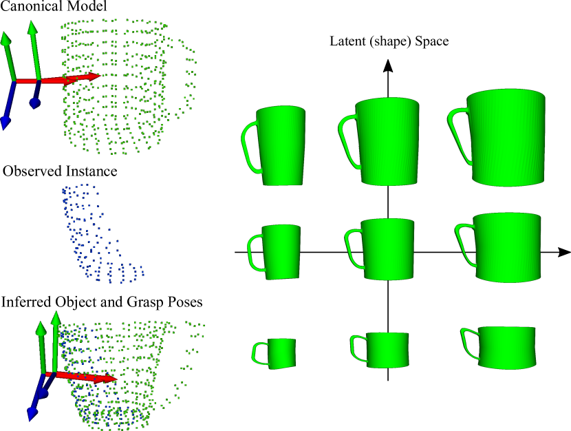
People can be given a screwdriver that they never saw before, and they will immediately know how to grasp and operate it by transferring previous manipulation knowledge to the novel instance. While this transfer happens effortless in humans, achieving such generalization in robots is challenging. Manipulating novel instances of a known object category is still an open problem. Although the manipulation of known objects can be planned offline, many open-world applications require the manipulation of unknown instances. Our approach transfers manipulations skills to novel instances by means of a novel latent space non-rigid registration (Fig. 1).
Robots are often equipped with RGB-D sensors to perceive their environment in 3D. In order to reconstruct the full shape of an object—desirable for planning grasping—multiple views of the object must be taken and fused into a single 3D model. However, robots are not always able to obtain the required views for generating the full model, because of obstructions or unreachable observation poses, e.g., an object lying at the inner corner of a shelf. Fortunately, it is frequently not necessary to measure occluded object parts if they can be inferred from prior object knowledge.
In this paper, we propose a method for generating grasping motions for novel instances from a single view by making use of category-level extrinsic shape information residing in a learned latent space. Our method accumulates object shape from multiple known instances of a category in a canonical model. The learned latent space of shape variations enables a category-specific shape-aware non-rigid registration procedure that establishes correspondences between the novel view and the canonical model. By linearly interpolating between low-dimensional shape parameters of the known instances, and by extrapolation in this shape space, a manifold of plausible shapes belonging to the modeled category can be generated.
Our method finds a transformation from the canonical model to a view of a novel instance in the latent space—linearly interpolated and extrapolated from other transformations found within the class—which best matches the observed 3D points. This estimates the shape parameters of the novel instance and allows for inference of its occluded parts. The non-rigid transformation maps control poses from the canonical model to the novel instance, which are then used to generate the grasping motion for it.
The remainder of this paper is organized as follows. In the next section, we discuss related works. Section III gives an overview of our approach. The necessary background is then presented in Section IV. In Section V, we describe our approach in detail. We evaluated our method in multiple experiments which are presented in Section VI.
II Related Work
II-A Non-Rigid Registration
Since Chen and Medioni [1] introduced the Iterative Closest Point (ICP) algorithm, numerous variations have been proposed for rigid registration [2, 3]. For non-rigid registration, priori restrictions or regularization on the motion or deformation of the points between sets are often imposed. Different transformation priors such as isometry [4, 5, 6], elasticity [7], conformal maps [8, 9, 10], thin-plate splines [11, 12], and Motion Coherence Theory [13] have been used to allow for or to penalize different types of transformations.
Many methods use non-rigid registration for surface reconstruction [14, 15, 16, 17, 18, 19]. Brown and Rusinkiewicz [12], Li et al. [14] proposed surface reconstruction methods for global non-rigid registration. Methods such as Li et al. [15], Zollhöfer et al. [20] use a Kinect depth camera to capture an initially low-resolution 3D surface and use non-rigid registration to continuously add higher-frequency details to the model with each new frame.
Recently, Newcombe et al. [19] proposed a non-rigid dense surface reconstruction method using dense non-rigid registration. From a sequence of depth images, they calculate a dense 6-dimensional warp field between frames. They then undo the transformations between each frame and rigidly fuse the scans into one canonical shape. The dense warp field is estimated by minimizing an energy function. Although this method is able to deform a scene in real-time toward a canonical shape, the use optical flow constraints makes this method inadequate for large deformations or strong changes in illumination and color.
II-B Class-Level Shape Spaces
To create a parameterized space of shapes, several methods have been proposed. Blanz and Vetter [21] create a morphable model of faces able to create novel faces and to interpolate between faces using a few parameters. Similarly, Allen et al. [11] create a shape space of human bodies using human body range scans with sparse 3D markers. Hasler et al. [22] extend this space to include pose, creating a unified space of both pose and body shape. This allows them to model the surface of a body in various articulated poses more accurately.
Other approaches as the one presented by Nguyen et al. [23] establish shape correspondences by creating collections of similar shapes and optimizing the mapping at a global scale. Huang et al. [24] also use collections of shapes to enforce global consistency. They create a small collection of base shapes from which correspondences are established between all other shapes.
Burghard et al. [25] propose an approach to estimate dense correspondences on a shape given initial coarse correspondences. They use the idea of minimum description length to create a compact shape space of related shapes with strongly varying geometry. However, this method does not perform well in the presence of noise or incomplete scans. Engelmann et al. [26] learn a compact shape manifold which represents intra-class shape variance, allowing them to infer shape in occluded regions or regions where data might be missing or noisy such as on textureless, reflective, or transparent surfaces. This approach however does not give correspondences between points and do not offer any kind of transformation, which limits its applicability to transferring grasping knowledge.
II-C Transferring Grasping Skills
Stueckler et al. [27] proposed a method for manipulation skill transfer using non-rigid registration. The registration finds a non-rigid transformation between a known instance where manipulation information—such as grasp poses or motion trajectories—are available and a novel instance from the same class. The non-rigid transformation is applied to map trajectory control poses towards the newly observed instance, which allows for use of the novel object. We extend this work by modeling shape and grasping not for single known instances, but within a category, which allows for learning typical variations of a canonical model.
Alternative methods as in [28] transfer grasp poses by segmenting the objects in primitive shapes according to their RGB-D appearance. Because this method is based on templates primitives, it is not able to handle occlusions efficiently. In [29] and in [30], grasp poses are transferred using the same contact warp method which minimizes the distance between assigned correspondences. However, both approaches require a fully observed object and focus only on the final result of grasping, namely on grasp poses, while our approach addresses the process of grasping.
III Problem Statement
We propose a new approach for transferring grasping skills based on a novel method for non-rigid registration. This method incorporates category-level information by learning a shape space of the category. By incorporating this information into the registration, we can avoid unlikely shapes and focus on deformations actually observed within the class. Thus, the resulting grasping motion is able to tolerate the noise and occlusions typical of data measured by 3D sensors. Furthermore, the generated space can be used to create novel instances and to interpolate and extrapolate between previous ones.
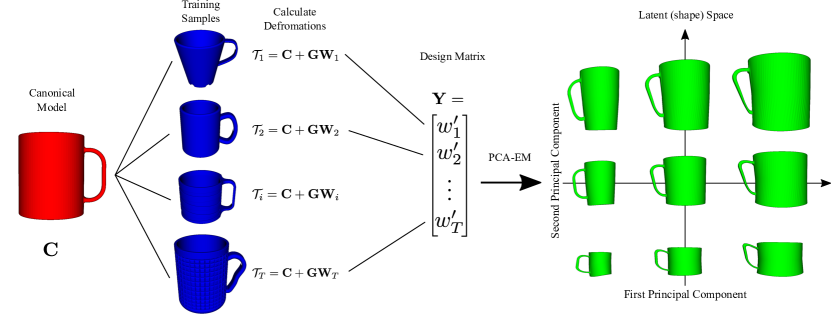
Our method is divided into two phases: a learning phase and an inference phase (Fig. 2 and 3). In the learning phase, the objective is to create a class-specific linear model of the transformations that a class of objects can undergo. We do this by first selecting a single model to be a canonical instance of the class, and then we find the transformations relating this instance to all other instances of the class using Coherent Point Drift (CPD) [13]. We then find a linear subspace of these transformations, which becomes our transformation model for the class. In the inference phase, the objective is: given a newly observed instance, search this subspace of transformations to find the transformation which best relates the canonical shape to the observed instance. Grasping information from the canonical model is also transformed to the observed instance and used to generate the grasping motion of the robot.
The transformations are represented by a dense deformation field plus a single rigid transformation; the latter is included to account for small global misalignments. This allows points defined in the space of the canonical shape to be transformed into the space of an observed instance. These points do not need to be known a priori for the learning phase and can be added at any time after the registration has completed.
The main contributions of this paper are:
-
1.
a novel learned non-rigid registration method that finds a low-dimensional space of deformation fields; this method can be used to interpolate and extrapolate between instances of a class of objects to create novel instances and
-
2.
the application of this non-rigid registration method to transfer grasping skills.
IV Coherent Point Drift
We briefly review the Coherent Point Drift (CPD) [13] method on which our non-rigid registration is based.
Given two point sets, a template set and a reference point set , CPD tries to estimate a deformation field mapping the points in to . The points in are considered centroids of a Gaussian Mixture Model (GMM) from which the points in are drawn. CPD seeks to maximize the likelihood of the GMM while imposing limitations on the motion of the centroids. CPD imposes a smoothness constraint on the deformation of the points in the form of motion coherence, which is based on Motion Coherence Theory [31]. The idea is that points near each other should move coherently and have a similar motion to their neighbors. Maximizing the likelihood of the GMM is equivalent to minimizing the energy function:
| (1) |
where is a parametrized transformation from the template point set to the reference set. The first term of Eq. (1) penalizes the distance between points after applying the transformation , and the second term is a regularization term which enforces motion coherence.
For the non-rigid case, the transformation is defined as the initial position plus a displacement function :
| (2) |
where is defined for any set of -dimensional points as:
| (3) |
is a Gaussian kernel matrix which is defined element-wise as:
| (4) |
is a matrix of kernel weights, and is a parameter that controls the strength of interaction between points. An additional interpretation of is as a set of -dimensional deformation vectors, each associated with one of the points of . For convenience in the notation, will be denoted . Note that can simply be computed by Eq. (4), but the matrix needs to be estimated.
CPD uses an Expectation Maximization (EM) algorithm derived from the one used in Gaussian Mixture Models [32] to minimize Eq. (1). In the E-step, the posterior probabilities matrix is estimated using the previous parameter values. To add robustness to outliers, an additional uniform probability distribution is added to the mixture model. This matrix is defined element-wise as:
| (5) |
where reflects the assumption on the amount of noise.
In the M-step, the matrix is estimated by solving the equation:
| (6) |
where represents a column vector of ones and is the inverse diagonal matrix.
In our method, we use the canonical shape for the deforming template shape and each training example as the reference point set . Hence, the transformations are defined as
| (7) |
where is the matrix computed by taking training example as the reference point set .
V Method
Our learning-based approach has an initial training phase in which the latent space for a class of objects is built. With the latent space of the object class, inference can be performed to find a transformation which relates one of the shapes from the class called the canonical shape to fully or partially-observed novel instances. The transformation is represented by a dense deformation field plus a single rigid transformation. Finally, we transform all the grasping information to the new instance.
V-A Categories and Shape Representation
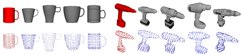
We define a category or class as a set of objects which share the same topology and a similar extrinsic shape. A category is composed of a set of training sample shapes and a canonical shape that will be deformed to fit the shape of the training and observed samples. To represent a shape, we use point clouds, which can be generated from meshes by ray-casting from several viewpoints on a tessellated sphere and then down-sampling with a voxel grid filter. The canonical shape can be chosen by heuristics or chosen as the shape with the lowest reconstruction energy after finding the deformation field of all other training examples. Fig. 4 shows both the mesh and the resulting uniformly-sampled point clouds of object samples of two different categories.
Each class must specify a canonical pose and reference frame, which are essential for initial alignment. For example: for Mugs, we can align all instances such that their top is open upward with all the handles pointing towards the right.
V-B Low-Dimensional Deformation Field Manifold
Once we have a set of training examples and a canonical shape, we need to find the deformations from the canonical shape to all other training shapes. Here we make use of the Coherent Point Drift method [13].
CPD provides a dense deformation field, allowing us to find deformation vectors for novel points, even those added after the field is created, which in turn allows us to apply the method for transferring grasping skills. Additionally, CPD allows us to create a feature vector representing the deformation field. Importantly, this vector has the same length for all training examples and elements in the vector correspond with the same elements in another. This will allow us to construct a latent space in later steps.
From Eq. (7), we see that the deformation field function is defined by the matrices and . Moreover, from Eq. (4) we see that is a function only of the canonical shape and remains constant for all training examples. Thus, the entire uniqueness of the deformation field for each training example is captured by the matrix .
For each training example , we take the matrix from its deformation field and convert it into a row vector , which becomes the feature descriptor of that deformation field. The vectors are then normalized resulting in zero-mean and unit-variance vectors which are then assembled into a design matrix . Finally, we apply Principle Component Analysis (PCA) on this matrix to find a lower-dimensional manifold of deformation fields for this class.
PCA finds a matrix of principle components that can be used to estimate a matrix of observation vectors given a small set of latent variables, i.e., :
| (8) |
For a new normalized set of observations , the latent variables can be found by:
| (9) |
We find the matrix using the PCA Expectation Maximization (PCA-EM) algorithm [33]. We choose this method over analytical algorithms due to its superior performance in situations with high dimensions and scarce data and also because of its greater numerical stability.
Much like with CPD, we alternate between an E- and M-step. The E-step is given by:
| (10) |
whereas the M-step is defined by:
| (11) |
This method is shown to converge to a local minimum using standard EM convergence proofs [34]. Additionally, it has been shown that the only stable local extremum is the global maximum [35, 36], meaning the algorithm will always converge to the correct result with enough iterations.
Using Eq. (9), a deformation field can now be described by only latent parameters. Similarly, any point in the latent space can be converted into a deformation field transformation by first applying Eq. (8) and converting the result into a matrix after the respective denormalization. Thus, moving through the -dimensional space linearly interpolates between the deformation fields.
The matrix and the canonical shape together represent the transformation model for a class. Figure 2 gives an overview of the training phase which is also summarized in Algorithm 1.
Input: A set of training shapes in their canonical pose and reference frame
Output: A canonical shape and a latent space of deformation fields represented by .
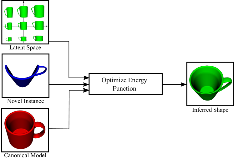
V-C Shape Inference for Novel Instances
With the transformation model, we can now start registering the canonical shape to novel instances in order to estimate the underlying transformation. The parameters of the transformation are given by the parameters of the latent vector plus an additional seven parameters of a rigid transformation . The rigid transformation is meant to account for minor misalignments in position and rotation between the target shape and the canonical shape at the global level.
We concurrently optimize for shape and pose using gradient descent. We expect local minima, especially with regard to pose, therefore our method, as CPD and ICP, requires an initial coarse alignment of the observed shape. We want to find an aligned dense deformation field which when applied to the canonical shape , minimizes the distance between corresponding points in the observed shape . Specifically, we want to minimize the energy function:
| (12) |
where the function applies the rigid transformation given parameters.
V-D Transferring Grasping Skills
From experiences with an anthropomorphic robotic hand, namely the multi-fingered Schunk hand [37], we observed that a functional grasping cannot be described only by the final joint configuration of the entire system (manipulator plus hand). During the motion, the hand can make use of geometrical and frictional constraints to increase the chances of a successful grasping. For instance, for grasping drills, we can first make a lateral contact with the palm followed by a contact of the thumb with the rear part of tool, creating static frictional forces that may help during the grasp. Therefore, we use the term grasping when we refer to the complete action and the term grasp for the result of this action.
We represent a grasping action as a set of parametrized motion primitives. The parameters of the motion primitives are poses expressed in the same coordinate system of the shape of the object. These poses need to be defined only for the canonical model. For new instances, the poses are found by warping the poses of the canonical model to the instance. Because the warping process can violate the orthogonality of the orientation, we orthonormalize the warped quaternions. Additional parameters of the motion primitives such as velocities and accelerations can also be derived from the warped poses.
Input: Transformation model (, ) and observed shape
-
1.
Use Eq. (8) to create vector and convert it into matrix .
- 2.
-
3.
Apply the rigid transformation to the deformed .
Output: Non-rigid transformation given by deformation field description and rigid transform .
VI Experimental Results
We tested our method on two categories: Mugs and Drills. We obtained the models from two online CAD databases: GrabCad111https://grabcad.com/library and the 3DWarehouse222https://3dwarehouse.sketchup.com/. The meshes were converted into point clouds by ray-casting from several viewpoints on a tessellated sphere and down-sampling with a voxel grid filter. We trained the Mug and Drill models with their canonical shape and additional 21 and 9 samples, respectively. The meshes of some of the samples together with the uniformly sampled point clouds are shown in Fig. 4.
We evaluated the robustness of our method to noise, misalignment, and occlusion and compared our results against results given by CPD. Noise was added to each point by randomly sampling a point from a normal distribution and scaling it by a noise factor. Misalignment was generated by adding a rigid transformation to the observed shape. For the translation, we uniformly sampled a three-dimensional unit vector and multiplied it by the following factors: . For the orientation, a three-dimensional unit rotation axis was uniformly sampled and combined with the following angles: ], making use of the axis-angle representation. Each test was run on a full view of the object and on six different partial views of the object. To obtain the partial views, we used ray-casting on a single view of a tessellated sphere.
In all experiments, we parametrized CPD with the following values and . For creating the shape space, the number of latent variables was set to capture at least 95% of the variance of each class, and the class canonical shapes were selected by experts.
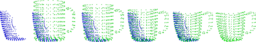
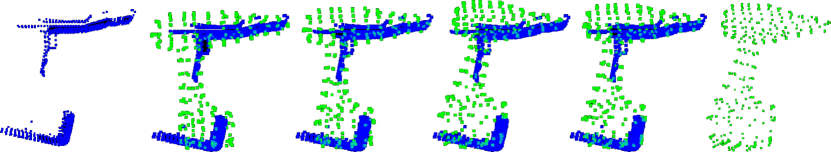
Fig 5 shows, for both categories, how the canonical shape is deformed to a single view of an observed instance. Note that our method is able to reconstruct occluded parts, as for example, the handles of the mugs.
For the evaluation, we take the noiseless fully-observed shape as the ground truth and the following error function:
| (13) |
where is the transformed canonical shape and is the ground truth shape. To compute the final error, we average the errors resulting from each partial view and from each test sample.
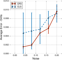
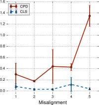
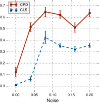
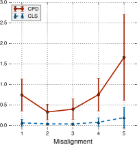
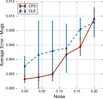
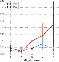
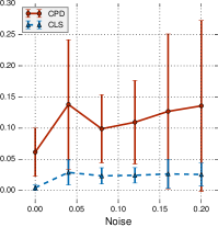
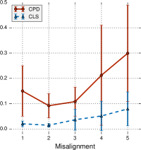
The results of our experiments are plotted in Fig. 7. We use the abbreviation CLS (Categorical Latent Space) for referring to our method. When a shape is fully visible with or without noise, CPD outperforms our method. This is rather to be expected as CPD is the source of training data from which we build our registration model. On the other hand, when the observed shape is misaligned, our method outperforms CPD, which can be explained by the additional rigid transformation component of our method. Moreover, when the shape becomes partially occluded, the method also outperforms CPD thanks to the topological information that lies in the latent space, which is not available in CPD.
Fully observed shapes Partially observed shapes
For testing the grasping transfer, we conducted a set of experiments using the five-fingered Schunk hand, which has a total of Degrees of Freedom (DoF) from which are fully actuated. The experiments were carried out in the Gazebo simulation environment. The tests were performed on the Drill category. Due to the reduced number of meshes, we used cross-validation and created five transformation models leaving two testing samples for each transformation model. A trial was defined as successful if after the execution of the motion, the drill was held by the robotic hand. We got a success rate of on grasping the drills.
Failure cases occurred mainly for one reason, i.e., the size of the testing object was too small compared to the canonical shape. This indicated that the transformation model was not general enough, mainly due to the reduced number of training samples. The small size of the objects also caused collisions between the fingers at the moment of grasping the handle. However, we expect to tackle this problem in the future by inferring information from the shape such as the number of fingers required for grasping.
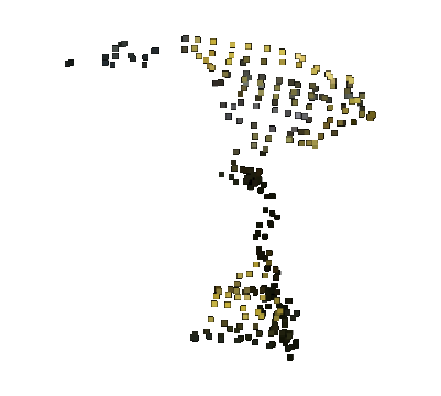
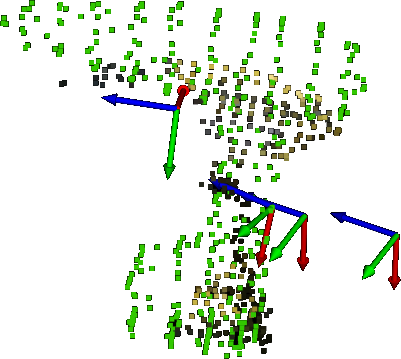
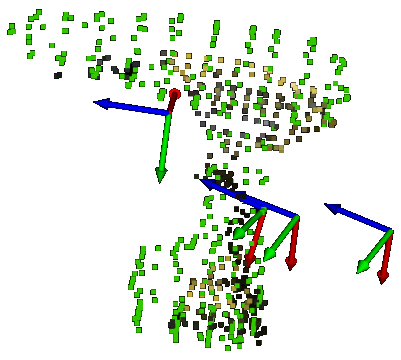
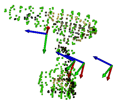
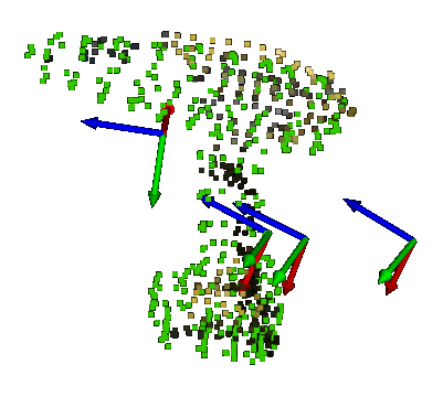
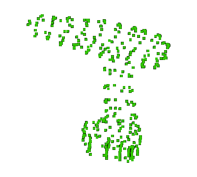
We tested our approach with real sensory data coming from a Kinect v2 sensor [38]. We trained a single latent space model with training samples and the canonical model. Our method was able to generate plausible category-alike shapes and grasping poses in each of three different trials. The inference in average took 6 s on a Corei7 CPU 2.6 GHz with 16GB RAM. This demonstrates that our method can be used on-board in real robotic platforms. The result of the registration is presented in Fig. 6.
VII Conclusion
We presented a novel approach for transferring grasping skills based on a latent space non-rigid registration method, which is able to handle fully observed and partially observed shapes. We demonstrated its robustness especially to noise and occlusion. We evaluated our method on two sets of shapes and found that while the method performed slightly worse than conventional CPD on noiseless, fully observed shapes, when shapes were partially occluded, our method was much more able to recover the true underlying shape and reported lower average error. Successful application of the non-rigid registration for transferring grasping skills was also demonstrated both with synthetic and real sensory data.
In the future, we would like to extend our approach to more complex objects that require a part-based modeling approach.
Acknowledgements
This work was supported by the European Union’s Horizon 2020 Programme under Grant Agreement 644839 (CENTAURO) and the German Research Foundation (DFG) under the grant BE 2556/12 ALROMA in priority programme SPP 1527 Autonomous Learning.
References
- Chen and Medioni [1992] Y. Chen and G. Medioni, “Object modelling by registration of multiple range images,” Image and Vision Computing, vol. 10, no. 3, pp. 145–155, 1992.
- Rusinkiewicz and Levoy [2001] S. Rusinkiewicz and M. Levoy, “Efficient variants of the ICP algorithm,” in 3-D Digital Imaging and Modeling. Proceedings of Third International Conference on. IEEE, 2001, pp. 145–152.
- Holz et al. [2015] D. Holz, A. E. Ichim, F. Tombari, R. B. Rusu, and S. Behnke, “Registration with the Point Cloud Library: a modular framework for aligning in 3-D,” IEEE Robotics & Automation Magazine, vol. 22, no. 4, pp. 110–124, 2015.
- Bronstein et al. [2006] A. M. Bronstein, M. M. Bronstein, and R. Kimmel, “Efficient computation of isometry-invariant distances between surfaces,” SIAM Journal on Scientific Computing, vol. 28, no. 5, pp. 1812–1836, 2006.
- Tevs et al. [2009] A. Tevs, M. Bokeloh, M. Wand, A. Schilling, and H.-P. Seidel, “Isometric registration of ambiguous and partial data,” in Computer Vision and Pattern Recognition, CVPR. IEEE Conference on. IEEE, 2009, pp. 1185–1192.
- Ovsjanikov et al. [2010] M. Ovsjanikov, Q. Mérigot, F. Mémoli, and L. Guibas, “One point isometric matching with the heat kernel,” in Computer Graphics Forum, vol. 29, no. 5. Wiley Online Library, 2010, pp. 1555–1564.
- Hahnel et al. [2003] D. Hahnel, S. Thrun, and W. Burgard, “An extension of the ICP algorithm for modeling nonrigid objects with mobile robots,” in Proceedings of the 18th International Joint Conference on Artificial Intelligence, San Francisco, CA, USA, 2003, pp. 915–920.
- Lévy et al. [2002] B. Lévy, S. Petitjean, N. Ray, and J. Maillot, “Least squares conformal maps for automatic texture atlas generation,” in ACM Transactions on Graphics (TOG), vol. 21, no. 3, 2002, pp. 362–371.
- Zeng et al. [2010] Y. Zeng, C. Wang, Y. Wang, X. Gu, D. Samaras, and N. Paragios, “Dense non-rigid surface registration using high-order graph matching,” in Computer Vision and Pattern Recognition (CVPR), IEEE Conference on. IEEE, 2010, pp. 382–389.
- Kim et al. [2011] V. Kim, Y. Lipman, and T. Funkhouser, “Blended intrinsic maps,” ACM Transactions on Graphics (Proc. SIGGRAPH), vol. 30, no. 4, Jul. 2011.
- Allen et al. [2003] B. Allen, B. Curless, and Z. Popović, “The space of human body shapes: reconstruction and parameterization from range scans,” in ACM Transactions on Graphics (TOG), vol. 22, no. 3, 2003, pp. 587–594.
- Brown and Rusinkiewicz [2007] B. J. Brown and S. Rusinkiewicz, “Global non-rigid alignment of 3-d scans,” in ACM Transactions on Graphics (TOG), vol. 26, no. 3. ACM, 2007, p. 21.
- Myronenko and Song [2010] A. Myronenko and X. Song, “Point set registration: Coherent point drift,” IEEE Transactions on Pattern Analysis and Machine Intelligence, vol. 32, no. 12, pp. 2262–2275, 2010.
- Li et al. [2008] H. Li, R. W. Sumner, and M. Pauly, “Global correspondence optimization for non-rigid registration of depth scans,” in Computer Graphics Forum, vol. 27, no. 5. Wiley Online Library, 2008, pp. 1421–1430.
- Li et al. [2009] H. Li, B. Adams, L. J. Guibas, and M. Pauly, “Robust single-view geometry and motion reconstruction,” in ACM Transactions on Graphics (TOG), vol. 28, no. 5, 2009, p. 175.
- Süßmuth et al. [2008] J. Süßmuth, M. Winter, and G. Greiner, “Reconstructing animated meshes from time-varying point clouds,” in Computer Graphics Forum, vol. 27, no. 5. Wiley Online Library, 2008, pp. 1469–1476.
- Wand et al. [2007] M. Wand, P. Jenke, Q. Huang, M. Bokeloh, L. Guibas, and A. Schilling, “Reconstruction of deforming geometry from time-varying point clouds,” in Proceedings of the Fifth Eurographics Symposium on Geometry Processing, Aire-la-Ville, Switzerland, Switzerland, 2007, pp. 49–58.
- Wand et al. [2009] M. Wand, B. Adams, M. Ovsjanikov, A. Berner, M. Bokeloh, P. Jenke, L. Guibas, H.-P. Seidel, and A. Schilling, “Efficient reconstruction of nonrigid shape and motion from real-time 3D scanner data,” ACM Transactions on Graphics (TOG), 2009.
- Newcombe et al. [2015] R. A. Newcombe, D. Fox, and S. M. Seitz, “Dynamicfusion: Reconstruction and tracking of non-rigid scenes in real-time,” in Proceedings of the IEEE Conference on Computer Vision and Pattern Recognition (CVPR), 2015, pp. 343–352.
- Zollhöfer et al. [2014] M. Zollhöfer, M. Nießner, S. Izadi, C. Rehmann, C. Zach, M. Fisher, C. Wu, A. Fitzgibbon, C. Loop, C. Theobalt et al., “Real-time non-rigid reconstruction using an RGB-D camera,” ACM Transactions on Graphics (TOG), vol. 33, no. 4, p. 156, 2014.
- Blanz and Vetter [1999] V. Blanz and T. Vetter, “A morphable model for the synthesis of 3D faces,” in Proceedings of the 26th Annual Conference on Computer Graphics and Interactive Techniques. ACM Press/Addison-Wesley Publishing Co., 1999, pp. 187–194.
- Hasler et al. [2009] N. Hasler, C. Stoll, M. Sunkel, B. Rosenhahn, and H.-P. Seidel, “A statistical model of human pose and body shape,” in Computer Graphics Forum, vol. 28, no. 2. Wiley Online Library, 2009, pp. 337–346.
- Nguyen et al. [2011] A. Nguyen, M. Ben-Chen, K. Welnicka, Y. Ye, and L. Guibas, “An optimization approach to improving collections of shape maps,” in Computer Graphics Forum, vol. 30, no. 5. Wiley Online Library, 2011, pp. 1481–1491.
- Huang et al. [2012] Q.-X. Huang, G.-X. Zhang, L. Gao, S.-M. Hu, A. Butscher, and L. Guibas, “An optimization approach for extracting and encoding consistent maps in a shape collection,” ACM Transactions on Graphics (TOG), vol. 31, no. 6, p. 167, 2012.
- Burghard et al. [2013] O. Burghard, A. Berner, M. Wand, N. Mitra, H.-P. Seidel, and R. Klein, “Compact part-based shape spaces for dense correspondences,” arXiv preprint arXiv:1311.7535, 2013.
- Engelmann et al. [2016] F. Engelmann, J. Stückler, and B. Leibe, “Joint object pose estimation and shape reconstruction in urban street scenes using 3D shape priors,” in German Conference on Pattern Recognition. Springer, 2016, pp. 219–230.
- Stueckler et al. [2011] J. Stueckler, R. Steffens, D. Holz, and S. Behnke, “Real-time 3D perception and efficient grasp planning for everyday manipulation tasks.” in ECMR, 2011, pp. 177–182.
- Vahrenkamp et al. [2016] N. Vahrenkamp, L. Westkamp, N. Yamanobe, E. E. Aksoy, and T. Asfour, “Part-based grasp planning for familiar objects,” in IEEE-RAS 16th International Conference on Humanoid Robots, Nov 2016, pp. 919–925.
- Stouraitis et al. [2015] T. Stouraitis, U. Hillenbrand, and M. A. Roa, “Functional power grasps transferred through warping and replanning,” in IEEE International Conference on Robotics and Automation (ICRA), May 2015, pp. 4933–4940.
- Amor et al. [2012] H. B. Amor, O. Kroemer, U. Hillenbrand, G. Neumann, and J. Peters, “Generalization of human grasping for multi-fingered robot hands,” in IEEE/RSJ International Conference on Intelligent Robots and Systems, Oct 2012, pp. 2043–2050.
- Yuille and Grzywacz [1988] A. L. Yuille and N. M. Grzywacz, “The motion coherence theory,” in Computer Vision., Second International Conference on. IEEE, 1988, pp. 344–353.
- Bishop [1995] C. M. Bishop, Neural networks for pattern recognition. Oxford university press, 1995.
- Roweis [1998] S. T. Roweis, “Em algorithms for pca and spca,” in Advances in Neural Information Processing Systems 10, M. I. Jordan, M. J. Kearns, and S. A. Solla, Eds. MIT Press, 1998, pp. 626–632.
- Dempster et al. [1977] A. P. Dempster, N. M. Laird, and D. B. Rubin, “Maximum likelihood from incomplete data via the EM algorithm,” Journal of the royal statistical society. Series B (methodological), pp. 1–38, 1977.
- Tipping and Bishop [1999a] M. E. Tipping and C. M. Bishop, “Mixtures of probabilistic principal component analyzers,” Neural computation, vol. 11, no. 2, pp. 443–482, 1999.
- Tipping and Bishop [1999b] ——, “Probabilistic principal component analysis,” Journal of the Royal Statistical Society: Series B (Statistical Methodology), vol. 61, no. 3, pp. 611–622, 1999.
- Ruehl et al. [2014] S. W. Ruehl, C. Parlitz, G. Heppner, A. Hermann, A. Roennau, and R. Dillmann, “Experimental evaluation of the schunk 5-finger gripping hand for grasping tasks,” in IEEE International Conference on Robotics and Biomimetics (ROBIO), Dec 2014, pp. 2465–2470.
- Fankhauser et al. [2015] P. Fankhauser, M. Bloesch, D. Rodriguez, R. Kaestner, M. Hutter, and R. Siegwart, “Kinect v2 for mobile robot navigation: Evaluation and modeling,” in International Conference on Advanced Robotics (ICAR), July 2015, pp. 388–394.