Bridging Hubbard Model Physics and Quantum Hall Physics in Trilayer Graphene/h-BN moiré superlattice
Abstract
The moiré superlattice formed by ABC stacked trilayer graphene aligned with a hexagonal boron nitride substrate (TG/h-BN) provides an interesting system where both the bandwidth and the topology can be tuned by an applied perpendicular electric field . Thus the TG/h-BN system can simulate both Hubbard model physics and nearly flat Chern band physics within one sample. We derive lattice models for both signs of (which controls the band topology) separately through explicit Wannier orbital construction and mapping of Coulomb interaction. When the bands are topologically trivial, we discuss possible candidates for Mott insulators at integer number of holes per site (labeled as ). These include both broken symmetry states and quantum spin liquid insulators which may be particularly favorable in the vicinity of the Mott transition. We propose feasible experiments to study carefully the bandwidth tuned and the doping tuned Mott metal-insulator transition at both and . We discuss the interesting possibility of probing experimentally a bandwidth (or doping) controlled continuous Mott transition between a Fermi liquid metal and a quantum spin liquid insulator. Finally we also show that the system has a large valley Zeeman coupling to a small out-of-plane magnetic field, which can be used to control the valley degree of freedom.
pacs:
Valid PACS appear hereI Introduction
Recently moiré superlattices in twisted Van der Waals heterostructures have been shown to realize several strongly correlated systems with high tunabilitySpanton et al. (2018); Cao et al. (2018a, b); Chen et al. (2018); Yankowitz et al. (2018). Correlated insulators and superconductors have been reported experimentally in twisted bilayer grapheneCao et al. (2018a, b); Yankowitz et al. (2018) and in ABC stacked graphene/hexagonal boron nitride (TG/h-BN)Chen et al. (2018). In this paper we focus on the TG/h-BN system.
BandwithChen et al. (2018) and even band topologyZhang et al. (2018) can be tuned by an applied perpendicular electric field in TG/h-BN. The displacement field provides an energy difference for electrons between the top and the bottom graphene layer, as illustrated in Fig. 1. For (this convention assumes that the h-BN layer on top is nearly aligned with the TG), the bands of the two valleys have zero Chern number while for they have non-zero Chern numbers Zhang et al. (2018); Chittari et al. (2018). Correlated insulators are found at and for the valence band of TG/h-BN at large Chen et al. (2018), where is defined as the total density of holes per moiré unit cell. When , physics similar to quantum Hall systems may be realizable. For trivial narrow bands that obtain when , the physics is expectedPo et al. (2018a) to be governed by an anisotropic Hubbard model (with small anisotropies) at leading order. Therefore TG/h-BN offers an experimental system where both Hubbard model physics and quantum Hall like physics can be simulated by simply switching the gate.
In this paper we describe several new aspects of the physics of TG/h-BN with a focus on the topologically trivial side (). We obtain an explicit interacting lattice model and estimate its parameters using the continuum description of the moire band structureBistritzer and MacDonald (2011). We use this lattice model to discuss the physics both deep in the correlated insulator regime and in the regime close to the Mott metal-insulator transition. We highlight the opportunities presented by this system to tunably study both the bandwidth tuned and doping tuned Mott transitions. We propose a number of transport experiments that can probe the Mott transition. We also present some new results on the topological bands that obtain for .
For , we build Wannier orbitals following the standard approach, and explicitly construct an effective tight-binding model. We project the Coulomb interactions to determine the effective interactions in the lattice model. The result is a spin-valley extended Hubbard model with Hund’s couplings as much smaller perturbations. The symmetry from the spin-valley degrees of freedom is mainly broken by a valley-contrasting flux in the hopping. Based on this model, we argue that the insulators found in the experiment should be understood as standard Mott insulators with charge frozen by Hubbard , in contrast to the nesting scenario in Ref. Zhu et al., 2018. In the limit of a nearly flat band, we argue that the insulator should be a ferromagnet for both and . For intermediate strength interactions, quantum spin liquids phases are promising candidates. In the vicinity of the Mott transition, a natural candidate is a spin liquid with neutral fermi surface coupled to an emergent gauge field.
The Mott metal-insulator transitionImada et al. (1998) is a fundamental phenomenon in condensed matter physics. Graphene moire systems like TG/h-BN offer a wonderful opportunity to controllably tune through the transition and explore its properties. It has long been appreciated that there are a number of distinct routes to the Mott transition in correlated solids. We describe distinctive signatures - visible in feasible experiments on TG/h-BN - of some of these distinct routes. Most striking is the possibilitySenthil (2008) of a bandwidth tuned continuous quantum critical Mott transition from the Fermi liquid metal to a spin liquid with a neutral Fermi surface. We show how to explore such a continuous Mott transition through simple transport experiments: a universal jump of residual resistivity at the critical point and Shubnikov-deHaas oscillations even inside the Mott insulator. Besides, we also discuss the possibility of a doping controlled continuous metal-insulator transition (DMIT) between the above two phases. Interestingly we find that the existing experimental data in Ref. Chen et al., 2018 may already have signatures of such a doping tuned continuous metal-insulator transition close to the filling .
Finally, we show that there is a large valley Zeeman coupling with averaged g factor . Therefore, a small out of plane magnetic field can polarize the valley and lead to a spin model. We discuss some consequences of this phenomenon.
For the topologically non-trivial side, valley preserving localized Wannier orbitals are impossible because of the non-zero Chern number . Related but distinct Wannier obstructions have also been discussed in the context of the twisted bilayer graphene systemPo et al. (2018a); Zou et al. (2018); Ahn et al. (2018); Song et al. (2018). The Wannier obstruction for the TG/h-BN system can not be removed by adding trivial bands and is therefore different from the fragile topology of the twisted bilayer graphene systemPo et al. (2018b). Following a similar treatment of twisted bilayer graphene in Ref. Po et al., 2018a we build a two orbital model on the triangular lattice, though the valley charge operator is not a sum of on-site terms. As argued in our previous workZhang et al. (2018) the side is promising to realize a quantum Anomalous Hall insulating state with strong interactions at . At fractional fillings, fractional quantum Anomalous Hall states may also be possible. The model derived in the present paper may in the future aid quantitative theoretical and numerical studies of these phenomena.

II Lattice Model For Side: spin-valley Hubbard Model
Band structures of TG/h-BN were calculated in Ref. Zhang et al., 2018 using a continuuum model. An important feature, as demonstrated experimentally in Ref. Chen et al., 2018, is that the band width can simply be tuned by the perpendicular displacement field (equivalently the potential difference ). More details of the band structure can be found in Appendix. A. Here we will use the results on the band structure to build an interacting lattice model with a focus on the topologically trivial side.
When , the valence band of each valley has zero Chern number and exponentially localized Wannier orbital on triangular lattice can be constructed for each valley separately. Following the methods in Appendix. C, we derived an interacting triangular lattice model which we describe below. At each site of the lattice there are 4 single particle states corresponding to 2 spin and 2 valley degrees of freedom. We work in the hole picture. We write the corresponding hole destruction operator as where is the valley index and is the spin index.
Microscopically the system has symmetries of charge conservation, spin rotation, and time reversal. The latter acts by flipping the two valleys111It is convenient to define time reversal without flipping the spin. We are free to combine this with a spin rotation to obtain a modified time reversal operation which flips both spin and valley. . :
| (1) |
For a large period moire structure (super)-lattice translations are an excellent symmetry as is a rotation (about a triangular site) which acts as
| (2) |
where is the site to which is taken by the rotation. Further, to an excellent approximation, the number of electrons within each valley is independently conserved. There is a corresponding valley charge symmetry. Finally within the continuum model there is a mirror reflection symmetry which also interchanges the two valleys (see Appendix. A):
| (3) |
where is generated from by a mirror reflection plane passing through where and are two unit vectors for the triangular lattice.
Note that there is no microscopic , and hence symmetry. If present, will forbid any non-zero Berry curvature at generic points in the MBZ. However, there exist non-zero Berry curvature close to the point and the MBZ boundaryZhang et al. (2018) though their sum cancels for the side. In the next sub-section we will also show that there is a large out of plane orbital magnetic moment at each momentum , which can not be compatible with the existence of both time reversal and symmetry.
Below we will derive a lattice model for the active bands. In the non-interacting limit, despite its absence as a microscopic symmetry, the lattice tight-binding model is symmetric under a rotation (about a triangular site) which acts as
| (4) |
where is the site to which is taken by the rotation. Thus flips the two valleys. This symmetry will be broken by interaction terms. However we will see that the part of the interaction that breaks is much smaller than other terms. Hence will be a good approximate symmetry of the effective lattice model though it is not a microscopic symmetry.
Using these symmetries, the lattice tightbinding model can be written
| (5) |
is valley index and is spin index. We need only the following hopping terms: , , and , and other terms that can be generated by rotation and reflection symmetry.
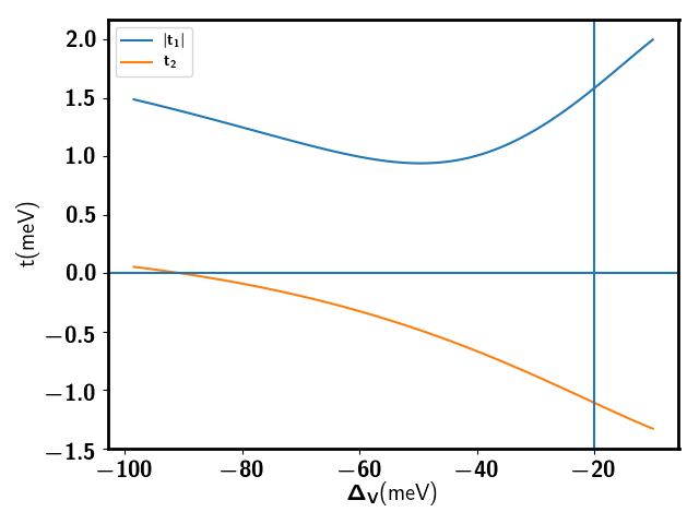
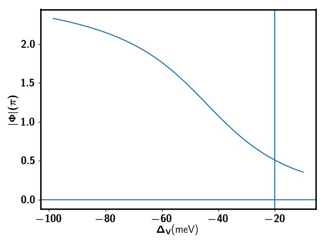
We list tight binding parameters for different in Table. 3. A key featurePo et al. (2018a) allowed by the symmetries is that within a single valley there is no time reversal, and hence there can be a non-zero flux through each triangular plaquette. However this flux must be opposite on neighboring plaquettes. From the explicit calculations of the tightbinding parameters we see that the staggered flux in one triangle for each valley is about in the regime meV. Such a valley contrasting flux strongly breaks the spin-valley symmetry222This is a combination of total charge transformation and the spin-valley rotation. down to . Here means an independent spin rotation combined with transformation for each valley . As we show in the next section, this symmetry breaking term will be inherited in the spin-valley model of the Mott insulator through super-exchange.
To obtain the interaction we start with the (screened) Coulomb interaction and project it on to the active valence bands, as explained in Appendix. C. We find
| (6) |
The first and second terms are the on-site and nearest neighbor repulsions respectively. The third term is an inter-site Hund’s interaction which preserves the symmetry (as do the first two terms). The last two terms however break . The term proportional to is the symmetry breaking part of the nearest neighbor Hund’s coupling (it breaks down to . Finally the last term (proportional to is an on-site inter-valley Hund’s coupling term which breaks down to (upto modding by a discrete group) . Here corresponds to the total charge conservation and corresponds to the valley charge conservation. is the spin rotation. In Table. 2 we list estimates of the parameters that enter the interaction Hamiltonian. We note that the dominant part of the interaction is given by the first 3 terms that preserve the symmetry. Thus to leading order we can only consider the symmetric part in the interaction and view the Hund’s coupling as small perturbations.
Eq. 5 and Eq. 6 give the lattice model for . The dominant terms correspond to a spin-valley extended Hubbard model on a triangular lattice. The most significant symmetry breaking is from the valley-contrasting flux in the hopping term. The interaction term is dominated by the on-site and nearest-neighbor Hubbard repulsion, which is guaranteed to be symmetric. However, there is also a small ferromagnetic Hund’s coupling term. Such a term plays an important role in the spin physics of the Mott insulator though its value is only of the Hubbard . The lattice model has an approximate symmetry, which is further broken down to by the on-site inter-valley Hund’s coupling term.
The inter-site Hund’s coupling, like all the other interactions, emerge from projection of the Coulomb interaction. Why does the pure density-density interaction give rise, after projection, to such a Hund’s interaction? The reason is that the microscopic density operator has a complicated form in terms of the lattice operators: with small but generically not zero. The term gives the on-site inter-valley Hund’s coupling and the term gives the inter-site Hund’s coupling and terms. The term originates from the fact that the inter-valley bilinear gives an oscillating density wave with momentum , where is the large momentum in the original Brillouin Zone of a pure graphene layer. The term comes from the fact that two nearest neighbor Wannier orbitals are not tightly confined and their electron densities overlapPo et al. (2018a). As is well-known the Wannier orbital is gauge dependent and a natural question to ask is if we can choose a good gauge to make these orbitals sufficiently tightly confined that . The answer is no: the reason is that local regions of the the valence band have non-zero Berry curvature (though there is no net Chern number). Such a non-zero Berry curvature is lost in the above one-orbital lattice model. The cost of this loss is that the microscopic density operator can not be purely on-site. In momentum space, . The form factor at small , where is the Berry connection. Due to the non-zero Berry curvature, the form factor can not be equal to in any gauge. Thus the density operator can not be written as in any gauge. As a consequence, in the lattice model (for any gauge choice), the microscopic density operator can not be pure on-site, and will include inter-site hopping terms. The original pure density-density interaction will then lead to density-density, density-hopping, hopping-hopping interaction in the lattice models. As explained in the Appendix. C, there are several terms generated, like correlated hopping and pair hopping terms. Of these the only term that does not involve double occupancy (which is suppressed by the Hubbard ) is the inter-site Hund’s coupling term .
II.1 Response to Magnetic Field: Valley Zeemann Coupling
Not only does the one-orbital lattice model lose the information of the Berry curvature of the Bloch states, it also loses information on the orbital magnetic moment. It is well established that Bloch states have an orbital magnetic moment in the directionXiao et al. (2010). A large factor for valley orbital magnetic moment has been proposed theoretically and verified experimentally in graphene systemsXiao et al. (2007); Koshino (2011); Ju et al. (2017). A recent experiment sees evidence of a very large factor(of the order of hundreds) for valley orbital magnetic moment in monolayer graphene/h-BN systemKomatsu et al. (2018). Motivated by these previous results, we study the possibility of a large valley orbital magnetic moment in the TG/h-BN system within the continuum model.
The corresponding g factor is
| (7) |
where we suppressed the valley index in and . is the valence band and labels the other eigenstates of .
Time reversal guarantees that . An external out-of-plane magnetic field couples linearly to this orbital moment:
| (8) |
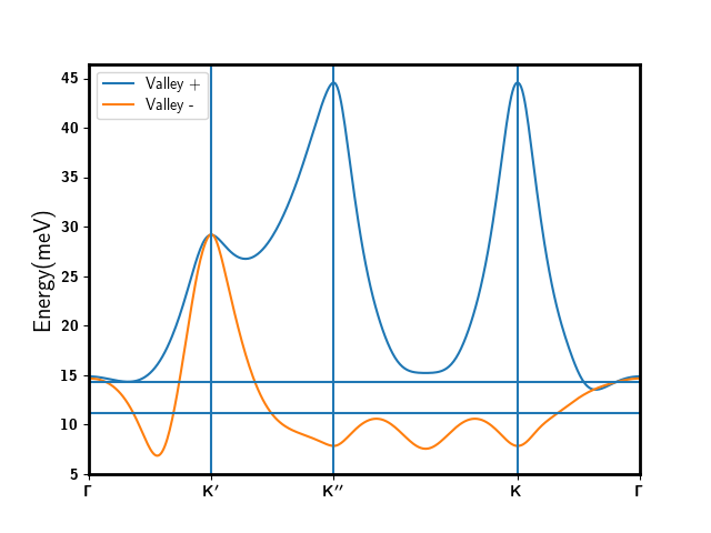
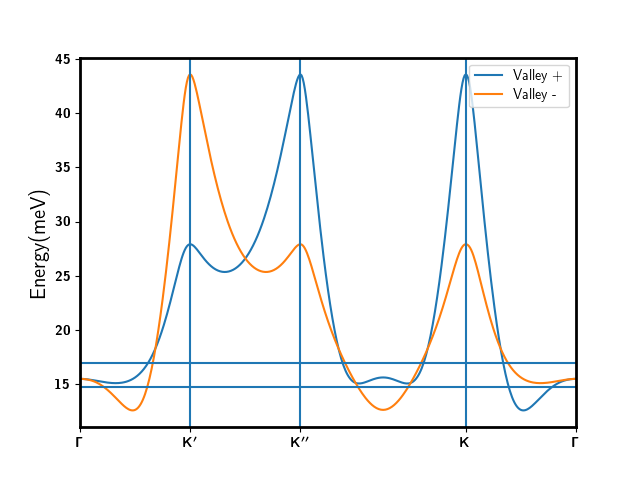
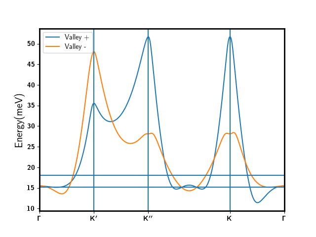
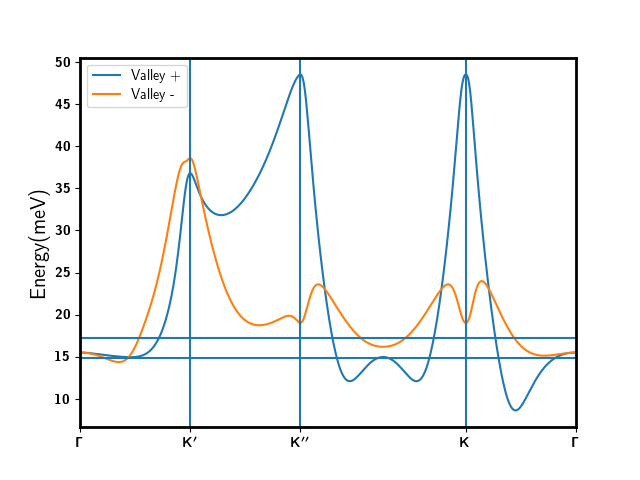
We calculated following Eq. 7 within the continuum model. Generically has a strong dependence on momentum . Its behavior for and are qualitatively different. The modified band structures that include this orbital magnetic field are presented in Appendix. A.
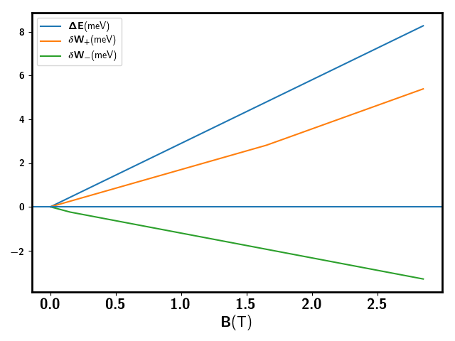
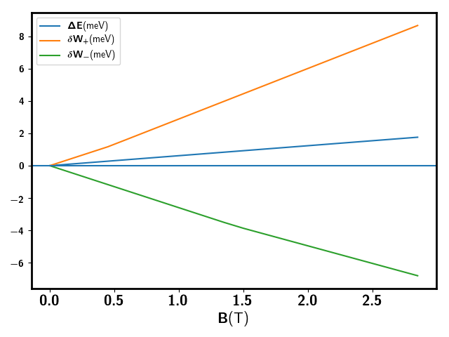
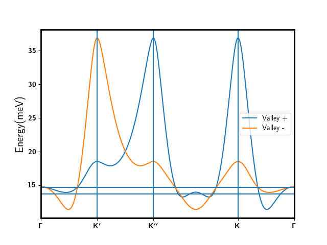
For , and for every . Therefore effectively we have a valley Zeeman coupling. The averaged factor is , much larger than the for spin. Therefore for , the most dominant effect of a small out-of-plane magnetic field is the splitting of valley energy, rather than the familiar spin Zeeman effect. In addition to the splitting of the average energy of the two valleys, the out-of-plane magnetic field also increases the bandwidth of one valley while reducing the bandwidth of the other valley, as shown in Fig. 4.
At small T , this valley Zeeman coupling term can be used to polarize the valley in the Mott insulating regime. A larger T can greatly increase the total bandwidth of the two valleys, which could destroy the Mott insulating phases. T gives a flux per moiré unit cell . The system then crosses over to the Hofstadter butterfly region.
III Strong Mott Insulators
We now discuss the experimentally observed insulating statesChen et al. (2018) at filling and for using the model described in Section. II. For the time being we only focus on the strong coupling limit . In this case charge is frozen and the low energy physics is governed by an effective spin-valley model. At each site, we define the spin operator and the valley operator . Here and are Pauli matrices for the spin and the valley respectively333We have assumed Einstein summation convention..
Using the standard expansion (see Appendix. E) we find the spin-valley model:
| (9) |
where with using the estimate in Table 2) and . has two contributions: a ferromagnetic part from the Hund’s coupling and an anti-ferromagnetic part from the standard super-exchange. Here should be understood as tensor product and is the abbreviation of the bilinear term . At , and are simply the corresponding valley and spin operator. At , and the corresponding spin or valley operator at each site is a matrix, which can be generated from the above bilinear terms of the fermionic operator. The factor is added to make the consistent with the traditional convention in the spin model once valley is polarized.
and are the symmetry breaking terms, mainly originating from super-exchange term involving opposite valleys. The valley-contrasting phase in the hopping is inherited in this term. We have and . The magnitude . Here is the phase of the hopping for the valley of the bond . meV is from the breaking part of the Hund’s coupling and can be neglected.
In the above we ignore and for simplicity. One can easily add and terms. For the fourth neighbor coupling, the breaking term from the valley-contrasting hopping phase should also be considered because has a large phase.
Even at second order of expansion, we need to keep four parameters for the spin-valley model: , , and . Ferromagnetic Hund’s coupling meV is even larger than and can not be ignored. These parameters can be tuned by and a rich phase diagram may be accessible in the experiment. For , and are generically of the same order of . Therefore the symmetry is strongly broken to 444Stictly speaking we need to further module some discrete symmetries. For , we also need to add the term in Eq. 6 which further breaks down the symmetry to .
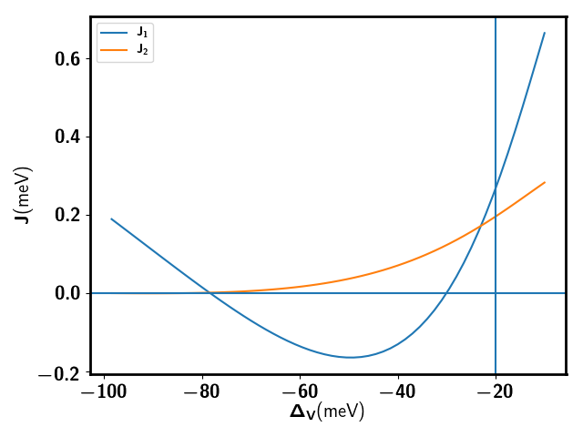
A plot of with is shown in Fig. 5. can be tuned to be either ferromagnetic or antiferromagnetic. Though we have presented estimates of the parameters , , and , their precise quantitative value are sensitive to assumptions used in the band structure calculation555Even the sign of is sensitive to . If is increased by a factor of , will be ferromagnetic in the whole region of .. It is useful therefore to view them as phenomenological parameters and discuss the general phase diagram of the model in Eqn. 9.
In the following two subsections we discuss the possible states for and region separately.
III.1 Ferromagnetic Region
In the strict limit , the Hund’s coupling dominates over the other terms. Then and . The Mott insulator should thus be a spin-valley ferromagnetic state.
For , the ground state should be ferromagnetic. The spin is polarized to any direction because of the spin rotation symmetry. For the valley, we need small anisotropic terms to decide whether or order is favored. The small -breaking Hund’s coupling ( meV) term in Eq. 6 favors valley polarization. But the anisotropy inherited from the valley-contrasting hopping term in of in Eq. 9 favors the polarization. Therefore interaction term and kinetic term compete with each other. At the flat band limit we always have the valley polarization. At any non-zero temperature , the spin ferro-magnetism will be disordered immediately because of the Mermin-Wagner theorem. However, valley polarization only breaks a discrete time reversal symmetry and will therefore be stable upto a finite temperature continuous transition in the Ising universality class. The spontaneous breaking of time reversal at small non-zero may give an exponentially suppressed but non-zero Hall conductivity. Such a valley polarization may also be detectable via the magneto-optical Kerr effect, as demonstrated in Ref.Huang et al., 2017 for spin ferromagnetism. As the out-of-plane magnetic moment from the valley is times larger than spin, this effect should be more significant for the valley polarized state. Once is increased, there can be a phase transition to an Inter-valley-coherent (IVC) order ( polarization). The IVC order does not break the time reversal symmetry. As it breaks the symmetry, there can be a Berezinskii-Kosterlitz-Thouless transition (BKT transition) at finite temperature.
For , just from the symmetric interaction in Eq. 9 there are several degenerate states. The true ground state will be selected from these by small anisotropies. The onsite inter-valley Hund’s coupling in Eq. 6 will select the spin polarized, valley singlet state as the ground state. Such a spin ferromagnetic state cannot have true long range order at any non-zero .
In summary, for limit, the ground states for both and are ferromagnetic. There should be a finite temperature transition corresponding to the valley polarization for and no transition for . We emphasize that the destruction of the spin ferromagnetism at finite temperature does not close the charge gap, which is at order and is thus much larger than the ferromagnetic scale .
III.2 Antiferromagnetic Region
With increasing , we enter a regime dominated by the the antiferromagnetic super-exchange: . The frustrated triangular geometry and the larger number of degrees of freedom666In the limit where we only keep we get an antiferromagnet with spins in either the fundamental representation (at ) or in the 6-dimensional representation (at ) of . Such models, even when nearest neighbor, are more likely to be in non-magnetic ground states than their versions. than the standard spin- model both enhance the effect of quantum fluctuations. Density Matrix Renormalization Group (DMRG) calculations of Eq. 9 may be able to map the phase diagram. Here we restrict ourselves to brief comments about special cases where we can relate the model to others studied in the literature. At , because of of the large valley Zeeman effect, a small out of plane magnetic field (of order T) can already give an energy splitting larger than and . Then the valley is frozen into a polarized state, and the effective model becomes the standard Heisenberg spin model. This model is already well studiedZhu and White (2015); Hu et al. (2015); Gong et al. (2017). At small , the ground state is the well known magnetically ordered state. At large ratio the ground state is a stripe antiferromagnet. In the intermediate region, a spin liquid phase is suggested from DMRG calculationsZhu and White (2015); Hu et al. (2015) though precisely which kind of spin liquid is not clear. Candidates are a chiral spin liquid or a Dirac spin liquid. Another special case is to apply a large in-plane magnetic field to polarize the spin. We expect then that the remaining valley degree of freedom forms a order at small .
IV Weak Mott insulators: possibility of a continuous Mott Transition
We now discuss the region close to the Mott metal-insulator transition for . In this region the spin-valley model derived in the previous section will not be adequate to discuss the Mott insulator. We could keep higher order terms in the expansion which will include multi-site ring exchange processesMotrunich (2005). Alternately the physics (even in the insulating side) may be directly discussed within the framework of the original Hubbard model.
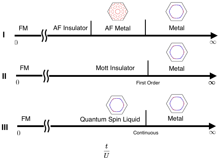
The Mott transition is of course most central to the study of correlated electron systems, and there is a vast literatureImada et al. (1998). It has long been appreciated that there are many distinct routes by which a metal may evolve into a Mott insulator at zero temperature. A common fate (realized in many experimental systems) is that the transition occurs between the paramagnetic metal and a magnetic insulator and is first order. Such a route can potentially be avoided in frustrated low dimensional lattices (as pertinent to the present paper). A different routeKrishnamurthy et al. (1990), suggested by a simple Hartree-Fock theory for an antiferromagnetic order parameter777In the following we will use the term ‘magnetic’ to denote ordering in the spin-valley space., is that the paramagnetic metal first undergoes a magnetic ordering transition into a magnetic metal. Eventually there is a second transition where the magnetic metal becomes a magnetic insulatior. A third fascinating alternative is that there is a continuous quantum critical Mott transition. A theory for such a continuous Mott transitionSenthil (2008) exists when the Mott insulator is a quantum spin liquid with a neutral spinon Fermi surface coupled to a gauge field. Such a continuous Mott transition may be relevant to experimentsKurosaki et al. (2005); Furukawa et al. (2018) on quasi-two dimensional organics. It is currently not at all clear if other kinds of Mott insulators admit continuous zero temperature quantum phase transitions into the paramagnetic metal.
The three possible evolutions discussed above from metal to Mott insulator are illustrated in Fig. 6.
The TG/h-BN (and other graphene moire systems) offers a tremendous opportunity to explore the band-width controlled Mott transition in a frustrated two dimensional lattice. There is a large body of very interesting prior work (see for instance Refs.Zhou et al., 2017; Kurosaki et al., 2005; Furukawa et al., 2015, 2018; Kanoda and Kato, 2011 ) on quasi-two dimensional organic salts (also on triangular lattices) which has probed the Mott transition with pressure as a tuning parameter at low temperature. Compared to the organics, the graphene system has the advantage that the electric control of bandwidth should make it a lot easier to tune through the Mott transition at low temperature and study it in exquisite detail.
With this in mind below we propose concrete (and we believe, feasible, in TG/h-BN) experiments that distinguish these various routes to the Mott transition.
IV.1 ‘Magnetic’ metal as an intermediate phase
We first consider the situation where the evolution from the metal to an antiferromagnetic (in spin-valley space) Mott insulator occurs in two stages. First there is a phase transition inside the metallic phase where the entiferromagnetic order onsets leading to a modification of the unit cell. This reconstructs the Fermi surface. With increasing amplitude of the antiferromagnetic order parameter, the Fermi surfaces will shrink and there will be a further transition to an antiferromagnetic insulator. This is the natural result of a Hartree-Fock treatment of the interactions. In the TG/h-BN context, such a symmetry breaking is suggested to arise from the nesting of the Fermi surfaces for by Ref. Zhu et al., 2018. Nesting driven theories have also been proposed for the twisted bilayer graphene systemIsobe et al. (2018); You and Vishwanath (2018).
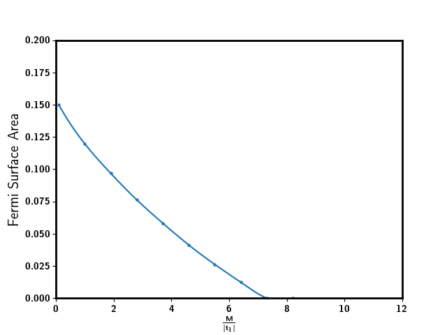
A clear experimental probe of this scenario is to study Shubnikov-DeHaas (SdH) oscillations in the resistivity in a perpendicular magnetic field. Through out the paramagnetic metal phase the Fermi surface area, and hence the SdH frequency, is fixed to be a constant by Luttinger’s theorem. In the antiferromagnetic metal, the reconstruction of the Fermi surface will change the SdH frequencies. On approaching the insulator these frequencies will decrease (possibly all the way to zero if the transition from the antiferromagnetic metal to antiferromagnetic insulator is continuous). Thus in this scenario there will be a change in the SdH frequencies before the metal becomes an insulator similar to Fig. 7. We caution that the SdH experiments should be performed in low perpendicular magnetic field so that they are a soft probe of the Fermi surface of the metal. At larger fields we will enter the quantum Hall regime and the oscillations may not directly reveal the Fermi surface structure of the zero field metal.
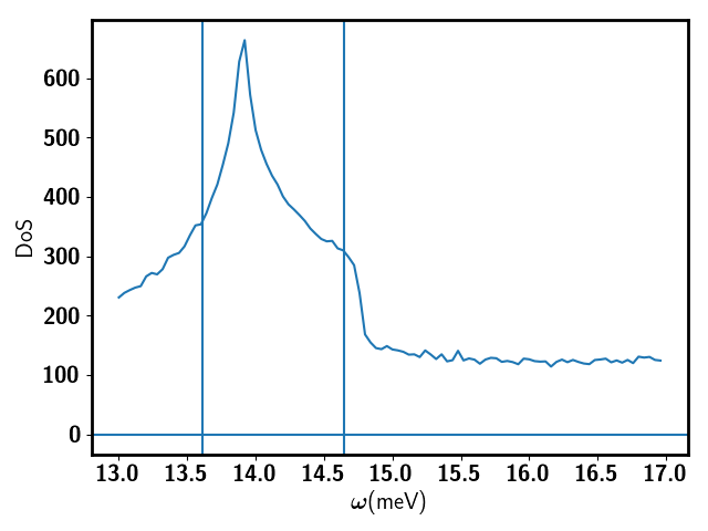
Let us briefly further comment on this simple Hartree-Fock scenario. In the strong Mott insulating region, the system may possibly be in a spin-valley ordered antiferromagnetic phase. However the mechanism for such ordering is different in the metal where it may be driven by an approximate nesting of the Fermi surface. Ref. Zhu et al., 2018 suggested such a nesting driven mechanism for by using a nearest neighbor tight binding model with valley contrasting flux . However, according to our calculation in Fig. 3, the flux is generically not equal to and are also necessary to reproduce the band structures. One natural question is whether this nesting of Fermi surfaces at is fine tuned or not. To test the robustness of the nesting properties of the Fermi surfaces, we calculated the Density of States(DoS) at meV using the continuum model with a mesh-grid in momentum space. The Van-Hove singularity in our model is away from the Fermi level at both and as shown in Fig. 8. From the Fermi surface plots in Appendix. A one can also see that there is no nesting instability in the particle-hole channel. Thus it is not obvious that the Hartree-Fock scenario is realized in the experimental system. We will therefore consider also other scenarios for the evolution from metal to insulator.
IV.2 First order Mott transition
A common possibility is that there is a first order transition between the paramagnetic metal and a Mott insulator. This may happen irrespective of the detailed description of the insulator (antiferromagnetic or quantum spin liquid). In this scenario the Fermi surface area seen in quantum oscillations should be constant in the metallic region. The first order transition will be accompanied by hysteresis when is cycled through the metal-insulator transition.
Further a first order transition will continue to (till a critical end-point in the Ising universality class) as a sharp transition. Hysteresis will be observed on crossing this finite phase boundary. If such a first order transition is indeed seen the shape of the transition line in the plane may provide some clues888Specifically, through the Claussius-Clapeyron relation, the metal-insulator phase boundary will tilt toward the insulator or metal depending on which state has more entropy at a given low . An antiferromagnetic insulator will at low- have lower entropy than the metal while some spin liquid insulators have higher entropy than a metal. about the nature of the Mott insulator.
IV.3 Bandwidth Controlled Continuous Metal-Insulator Transition
It is hard to theoretically rule out either of the two scenarios described above. However for the simpler problem of the spin- triangular lattice Hubbard model, it seems (from numerical studiesMotrunich (2005); Morita et al. (2002); Yang et al. (2010); Sheng et al. (2009); Szasz et al. (2018)) that a quantum spin liquid state forms in the weak Mott insulating regime. Many existing numerical calculationsMotrunich (2005); Morita et al. (2002); Yang et al. (2010); Sheng et al. (2009) as well as experimentsKanoda and Kato (2011); Zhou et al. (2017) on the organics are broadly consistent with this being a spin liquid with a neutral Fermi surface. A recent DMRG calculationSzasz et al. (2018) however reports instead a gapped chiral spin liquid in the weak Mott region. The TG/h-BN system has more degrees of freedom (than the spin- Hubbard model) at each site which may make a spin liquid more likely in this regime.
A remarkable feature of the neutral Fermi surface state is that it admits a continuous Mott transition to the metal. We turn therefore to how to look for this experimentally.
We first review a (small generalization of a) theorySenthil (2008) for the continuous Mott transition between a Fermi liquid metal and a spin liquid Mott insulator with a spinon Fermi surface coupled to a gauge field. The theory should work for both and . We use the slave boson constructionFlorens and Georges (2004): write . Here is a boson that carries the electric charge of the electron but not its spin/valley quantum numbers and (the spinon) is an electrically neutral fermion that carries the spin/valley quantum number. There is a constraint relating the number of and particles at each site of the lattice. Correspondingly there is a gauge redundancy and . A reformulation of the original electronic problem in terms of the variables necessarily must include a dynamical gauge field. In the Fermi liquid phase the spinons form a Fermi surface while , i.e, the bosons are in a superfluid state. Upon increasing interactions, a Mott insulator will form. Within this slave particle framework a natural Mott insulator is obtained by letting form a bosonic Mott insulator (where while keeping the -Fermi surfaceLee and Lee (2005). The resulting state is a spin liquid Mott insulator. The Mott metal-insulator transition is then associatedFlorens and Georges (2004); Senthil (2008); Mishmash et al. (2015) with the superfluid- Mott transition of the boson in the presence of the spinon fermi surface and the gauge field. As shown in Ref. Senthil, 2008 the resulting theory admits a continuous Mott transition which further is tractable. We now highlight two predictions of this theory for transport experiments that may be directly feasible in TG/h-BN.
The first pertinent prediction is a universal jumpSenthil (2008); Witczak-Krempa et al. (2012) by of the residual resistivity as the Mott critical point is approached from the metallic side999A simple explanation is from the Ioffe-Larkin rule which states that the physical resistivity where are the boson and -fermion resistivities respectively. Across the Mott transition, evolves smoothy while goes from (in the metal) to a universal constant (at the critical point) and eventually is (in the insulator ). The universal resistivity jump follows. Here is a universal number of . At a non-zero temperature the resistivity follows a useful scaling form described in Ref. Witczak-Krempa et al., 2012:
| (10) |
with , and in a clean sample. is the residual resistivity in the metal just before the Mott transition and is the parameter used to tune across the transition. For TG/h-BN this is accomplished very simply by the perpendicular displacement field. Thus the TG/h-BN system offers a promising platform to access such a continuous Mott transition.
A second prediction enables directly detecting the neutral Fermi surface, if it exists, just on the insulating side of the Mott transition: such a neutral Fermi surface will lead to SdH oscillationsMotrunich (2006); Chowdhury et al. (2018); Sodemann et al. (2018) in a weak Mott insulator. Detailed expressions for the temperature dependence of such oscillations may be found in Ref. Sodemann et al., 2018. The key point is that though the spinons are electrically neutral, they couple to the internal gauge field which locks to an external field : with a factor . In the vicinity of Mott transition point, will be of order . Therefore, the spinon fermi surface experiences an internal magnetic field and show quantum oscillation in the resistivity . At finite temperature, is large but finite even inside the Mott insulator, and therefore should also show quantum oscillation with frequency enlarged by a factor of compared to the Fermi liquid side. should show dependence on voltage and also temperature (see Ref. Sodemann et al., 2018). Due to the large valley Zeeman coupling, in practice, the oscillations may not have perfect periodicity in . However, an oscillating response to inside a Mott insulator will be strong evidence of the existence of neutral Fermi surface and emergent gauge field. Remarkably SdH oscillations in electrical resistivity have been reported in a recent experiment on a mixed valence insulatorXiang et al. (2018).
Another more direct evidence for a spinon Fermi surface state is metallic thermal transport . Measurement of the thermal conductivity is hard, but may be possible in the future.
We emphasize that the only currently understood theory for such a continuous Mott transition is when the insulator is a spin liquid with an emergent neutral fermi surfaceSenthil (2008). It is not known if there could be a direct continuous Mott transition between the paramagnetic metal and other kinds of Mott insulators (for instance an antiferromagnetic insulator or a chiral spin liquid). Such a continuous transition is exotic and will presumably involve a novel formulation. In TG/h-BN if none of the signatures discussed above are seen it will provide experimental evidence for such an exotic continuous quantum phase transition.
IV.4 Doping Controlled Continuous Metal-Insulator Transition
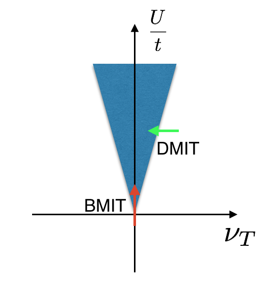
We now briefly address the Mott metal-insulator transition induced by doping away from commensurate filling. We will restrict to a discussion of the possibility of a continuous Mott transition101010Strictly speaking continuous Mott transitions are also possible out of paired spin liquid states. For instance if we dope a spin liquid a natural outcome is a superconductor. We then have a continuous Mott insulator -superconductor transition. which is possible if the Mott insulator is in the quantum spin liquid with a spinon Fermi surface. Theoretical descriptions of this Doping controlled Metal-Insulator Transition (DMIT) may be found in Refs. Senthil, 2008; Senthil and Lee, 2009; Senthil et al., 2004. Similar to our description of the Bandwidth controlled Metal-Insulator Transition (BMIT) in the previous subsection, we still use the slave boson theory: . In this case boson goes through a chemical potential tuned superfluid-Mott insulator transition. We focus here on the predictions for electrical transport. From the Ioffe-Larkin rule . In the clean limit at a small but non-zero it is knownSenthil et al. (2004) that the bosons have a resistivity due to scattering from (Landau-damped) gauge fluctuations. The weak logarithmic dependence may not be visible, and hence we may roughly expect the residual resistivity to jump as the critical point is approached from the metallic side just like at the BMIT.
Disorder effects will further affect the nature of the transition. First it is natural that at very low densities the dopants will be localized. The DMIT will then happen at a non-zero critical doping. The bosons are expected to have a universal conductivity at this disordered critical point which is distinct from that in the BMIT case. Thus, close to the critical point, we will once again have a universal jump of residual resistivity. Finally we note that near the disordered critical point, scaling similar to Eqn. 10 will hold but with different values for the exponents and . From the general result ( where is the spatial dimension) for disordered critical points, and the expectation in the presence of Coulomb interactions, we have for the DMIT, larger than for the BMIT of a clean system.
This brief discussion was meant to motivate an experimental study of the doping induced Mott transition in TG/h-BN. Interestingly the existing experimental data may already have evidence for a continuous doping controlled metal-insulator transition (DMIT) close to . In the Fig.3(a) of Ref. Chen et al., 2018, there is a critical V for which controls the total density (and also the bandwidth). Resistance increases with temperature when while when the resistance decreases with . At exactly the resistance is finite (around ) and constant in the temperature region K. Here K is the lowest temperature reachable in the reported experiment in Ref. Chen et al., 2018. This suggests a continuous metal-insulator transition. As a further test , we suggest measurements at lower temperature and to scale the data according to Eqn. 10 but with modified exponents as discussed above. It is also interesting to study the temperature dependence of the resistivity close to the critical point to search for non-Fermi-liquid behavior.
Finally within the theory of Ref. Senthil, 2008 the quasiparticle effective mass in the metallic phase will diverge as (upto log corrections) where is the doping away from the Mott insulator. This strong divergence may be observable through SdH measurements. (In contrast at the BMIT a much weaker log divergence of the effective mass is predicted).
V Comments for The side
When , the valence bands of two valleys have non-zero Chern numbers . Therefore it is not possible to construct localized Wannier orbitals for each valley separately. Following a similar constructionPo et al. (2018a) for twisted bilayer graphene, we can construct a two orbital model on the triangular lattice (see Appendix. D) but with a non on-site implementation of the the valley charge operator (i.e, the valley charge operator is not a sum of on-site terms). As a consequence, the interaction is in a complicated form, which makes an analytical treatment of the model very hard. Such a model may be useful for future numerical simulations.
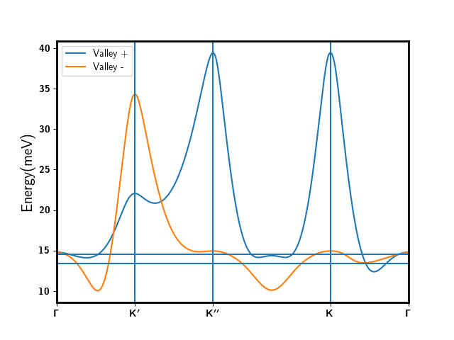
Despite the complexity of the model, the side can potentially realize interesting phases that show the Quantum Anomalous Hall effect (QAHE) and even the Fractional Quantum Anomalous Hall Effect (FQAHE) as proposed in our previous paperZhang et al. (2018). Especially, similar to quantum Hall ferromagnets, the insulator in the flat band limit should be a spin and valley polarized Chern insulator with Hall conductivity even at zero magnetic field. One concern about the experimental realization of this QAHE state is that the energies of the two valley polarizations are degenerate at zero magnetic field and hence the system forms domains. However one can align the valley polarization by cooling in an out-of-plane magnetic field. As shown in Fig. 10, there is also a valley Zeeman coupling when . The averaged factor is not so large as the side because changes sign in the MBZ. However, within our model, for a direction magnetic field with T, the band width of one valley becomes meV smaller than the other valley. Therefore, one valley polarization should be selected by a magnetic field and the system will be in the QAHE state. The total filling of the QAH insulator should also change with the magnetic field, leading to an insulating Landau fan: where is the uniform flux per moiré unit cell in units of . For zero twist angle, for T.
The proposal of quantum Hall ferromagnetism in our previous paper Zhang et al. (2018) assumes the flat band limit . The possible phases at intermediate remain an open question, as does the nature of the evolution from the weak interacting metal. A simple possibility is that there is a an intermediate ferromagnetic metallic phase which then gives way to the ferromagnetic insulator. Clarifying this will require developing tools to deal with strong correlations in partially filled dispersing Chern bands which we leave for the future.
VI Conclusion
In this paper we discussed several aspects of the moiré superlattice system in ABC stacked trilayer graphene on hexagonal boron nitride where previous work has shown that an applied vertical electric field can tune both the bandwidth and the topology. Our focus in this paper was complementary to our earlier work which mainly discussed the phenomenology of the topologically non-trivial side (. Here we mainly discussed the other topologically trivial side ( ). We explicitly constructed a lattice extended Hubbard model with degrees of freedom (but no symmetry). We used this model as a framework to discuss possible Mott insulating states at at total filling and . We also showed that due to a large valley Zeeman coupling a small perpendicular magnetic field may be a useful knob in this system.
We emphasized the opportunities provided by TG/h-BN (and other graphene moiré structures) to carefully experimentally study the bandwidth tuned Mott metal-insulator transition in a frustrated two dimensional lattice. We showed how simple electrical transport experiments can distinguish many different routes to the Mott transition. Particularly exciting is the possibility that this system realizes a quantum spin liquid with a spinon Fermi surface in the vicinity of the Mott transition. Such a state admits a direct continuous Mott transition to the Fermi liquid metal. The transport experiments we describe can specifically also probe this state and the continuous Mott transition.
Finally when and the bands have Chern number , we constructed a lattice two orbital model on the triangular lattice but with a non-local implementation of the valley charge operator (along the lines of the treatment of twisted bilayer graphene in Ref. Po et al., 2018a). It remains to be seen whether this kind of model can be useful for a future attack on strongly correlated partially filled Chern bands.
VII acknowledgement
We thank Yuan Cao, Debanjan Chowdhury, Mao Dan, Pablo Jarillo-Herrero, Adrian Po, Cecile Repellin, Ashvin Vishwanath, Feng Wang, Liujun Zou and Mike Zaletel for many inspiring discussions. This work was supported by NSF grant DMR-1608505, and partially through a Simons Investigator Award from the Simons Foundation to Senthil Todadri.
References
- Spanton et al. (2018) E. M. Spanton, A. A. Zibrov, H. Zhou, T. Taniguchi, K. Watanabe, M. P. Zaletel, and A. F. Young, Science 360, 62 (2018).
- Cao et al. (2018a) Y. Cao, V. Fatemi, A. Demir, S. Fang, S. L. Tomarken, J. Y. Luo, J. D. Sanchez-Yamagishi, K. Watanabe, T. Taniguchi, E. Kaxiras, et al., Nature 556, 80 (2018a).
- Cao et al. (2018b) Y. Cao, V. Fatemi, S. Fang, K. Watanabe, T. Taniguchi, E. Kaxiras, and P. Jarillo-Herrero, Nature 556, 43 (2018b).
- Chen et al. (2018) G. Chen, L. Jiang, S. Wu, B. Lv, H. Li, K. Watanabe, T. Taniguchi, Z. Shi, Y. Zhang, and F. Wang, arXiv preprint arXiv:1803.01985 (2018).
- Yankowitz et al. (2018) M. Yankowitz, S. Chen, H. Polshyn, K. Watanabe, T. Taniguchi, D. Graf, A. F. Young, and C. R. Dean, arXiv preprint arXiv:1808.07865 (2018).
- Zhang et al. (2018) Y.-H. Zhang, D. Mao, Y. Cao, P. Jarillo-Herrero, and T. Senthil, arXiv preprint arXiv:1805.08232 (2018).
- Chittari et al. (2018) B. L. Chittari, G. Chen, Y. Zhang, F. Wang, and J. Jung, arXiv preprint arXiv:1806.00462 (2018).
- Po et al. (2018a) H. C. Po, L. Zou, A. Vishwanath, and T. Senthil, arXiv preprint arXiv:1803.09742 (2018a).
- Bistritzer and MacDonald (2011) R. Bistritzer and A. H. MacDonald, Proceedings of the National Academy of Sciences 108, 12233 (2011).
- Zhu et al. (2018) G.-Y. Zhu, T. Xiang, and G.-M. Zhang, arXiv preprint arXiv:1806.07535 (2018).
- Imada et al. (1998) M. Imada, A. Fujimori, and Y. Tokura, Reviews of modern physics 70, 1039 (1998).
- Senthil (2008) T. Senthil, Physical Review B 78, 045109 (2008).
- Zou et al. (2018) L. Zou, H. C. Po, A. Vishwanath, and T. Senthil, Phys. Rev. B 98, 085435 (2018).
- Ahn et al. (2018) J. Ahn, S. Park, and B.-J. Yang, arXiv preprint arXiv:1808.05375 (2018).
- Song et al. (2018) Z. Song, Z. Wang, W. Shi, G. Li, C. Fang, and B. A. Bernevig, arXiv preprint arXiv:1807.10676 (2018).
- Po et al. (2018b) H. C. Po, L. Zou, T. Senthil, and A. Vishwanath, arXiv preprint arXiv:1808.02482 (2018b).
- Note (1) It is convenient to define time reversal without flipping the spin. We are free to combine this with a spin rotation to obtain a modified time reversal operation which flips both spin and valley.
- Note (2) This is a combination of total charge transformation and the spin-valley rotation.
- Xiao et al. (2010) D. Xiao, M.-C. Chang, and Q. Niu, Reviews of modern physics 82, 1959 (2010).
- Xiao et al. (2007) D. Xiao, W. Yao, and Q. Niu, Physical Review Letters 99, 236809 (2007).
- Koshino (2011) M. Koshino, Physical Review B 84, 125427 (2011).
- Ju et al. (2017) L. Ju, L. Wang, T. Cao, T. Taniguchi, K. Watanabe, S. G. Louie, F. Rana, J. Park, J. Hone, F. Wang, et al., Science 358, 907 (2017).
- Komatsu et al. (2018) K. Komatsu, Y. Morita, E. Watanabe, D. Tsuya, K. Watanabe, T. Taniguchi, and S. Moriyama, Science Advances 4, eaaq0194 (2018).
- Note (3) We have assumed Einstein summation convention.
- Note (4) Stictly speaking we need to further module some discrete symmetries.
- Note (5) Even the sign of is sensitive to . If is increased by a factor of , will be ferromagnetic in the whole region of .
- Huang et al. (2017) B. Huang, G. Clark, E. Navarro-Moratalla, D. R. Klein, R. Cheng, K. L. Seyler, D. Zhong, E. Schmidgall, M. A. McGuire, D. H. Cobden, et al., Nature 546, 270 (2017).
- Note (6) In the limit where we only keep we get an antiferromagnet with spins in either the fundamental representation (at ) or in the 6-dimensional representation (at ) of . Such models, even when nearest neighbor, are more likely to be in non-magnetic ground states than their versions.
- Zhu and White (2015) Z. Zhu and S. R. White, Physical Review B 92, 041105 (2015).
- Hu et al. (2015) W.-J. Hu, S.-S. Gong, W. Zhu, and D. Sheng, Physical Review B 92, 140403 (2015).
- Gong et al. (2017) S.-S. Gong, W. Zhu, J.-X. Zhu, D. N. Sheng, and K. Yang, Physical Review B 96, 075116 (2017).
- Motrunich (2005) O. I. Motrunich, Phys. Rev. B 72, 045105 (2005).
- Krishnamurthy et al. (1990) H. R. Krishnamurthy, C. Jayaprakash, S. Sarker, and W. Wenzel, Phys. Rev. Lett. 64, 950 (1990).
- Note (7) In the following we will use the term ‘magnetic’ to denote ordering in the spin-valley space.
- Kurosaki et al. (2005) Y. Kurosaki, Y. Shimizu, K. Miyagawa, K. Kanoda, and G. Saito, Phys. Rev. Lett. 95, 177001 (2005).
- Furukawa et al. (2018) T. Furukawa, K. Kobashi, Y. Kurosaki, K. Miyagawa, and K. Kanoda, Nature Communications 9, 307 (2018).
- Zhou et al. (2017) Y. Zhou, K. Kanoda, and T.-K. Ng, Rev. Mod. Phys. 89, 025003 (2017).
- Furukawa et al. (2015) T. Furukawa, K. Miyagawa, H. Taniguchi, R. Kato, and K. Kanoda, Nature Physics 11, 221 EP (2015).
- Kanoda and Kato (2011) K. Kanoda and R. Kato, Annual Review of Condensed Matter Physics 2, 167 (2011), https://doi.org/10.1146/annurev-conmatphys-062910-140521 .
- Isobe et al. (2018) H. Isobe, N. F. Yuan, and L. Fu, arXiv preprint arXiv:1805.06449 (2018).
- You and Vishwanath (2018) Y.-Z. You and A. Vishwanath, arXiv preprint arXiv:1805.06867 (2018).
- Note (8) Specifically, through the Claussius-Clapeyron relation, the metal-insulator phase boundary will tilt toward the insulator or metal depending on which state has more entropy at a given low . An antiferromagnetic insulator will at low- have lower entropy than the metal while some spin liquid insulators have higher entropy than a metal.
- Morita et al. (2002) H. Morita, S. Watanabe, and M. Imada, Journal of the Physical Society of Japan 71, 2109 (2002), https://doi.org/10.1143/JPSJ.71.2109 .
- Yang et al. (2010) H.-Y. Yang, A. M. Läuchli, F. Mila, and K. P. Schmidt, Phys. Rev. Lett. 105, 267204 (2010).
- Sheng et al. (2009) D. Sheng, O. I. Motrunich, and M. P. Fisher, Physical Review B 79, 205112 (2009).
- Szasz et al. (2018) A. Szasz, J. Motruk, M. P. Zaletel, and J. E. Moore, arXiv preprint arXiv:1808.00463 (2018).
- Florens and Georges (2004) S. Florens and A. Georges, Phys. Rev. B 70, 035114 (2004).
- Lee and Lee (2005) S.-S. Lee and P. A. Lee, Phys. Rev. Lett. 95, 036403 (2005).
- Mishmash et al. (2015) R. V. Mishmash, I. González, R. G. Melko, O. I. Motrunich, and M. P. Fisher, Physical Review B 91, 235140 (2015).
- Witczak-Krempa et al. (2012) W. Witczak-Krempa, P. Ghaemi, T. Senthil, and Y. B. Kim, Physical Review B 86, 245102 (2012).
- Note (9) A simple explanation is from the Ioffe-Larkin rule which states that the physical resistivity where are the boson and -fermion resistivities respectively. Across the Mott transition, evolves smoothy while goes from (in the metal) to a universal constant (at the critical point) and eventually is (in the insulator ). The universal resistivity jump follows.
- Motrunich (2006) O. I. Motrunich, Physical Review B 73, 155115 (2006).
- Chowdhury et al. (2018) D. Chowdhury, I. Sodemann, and T. Senthil, Nature communications 9, 1766 (2018).
- Sodemann et al. (2018) I. Sodemann, D. Chowdhury, and T. Senthil, Physical Review B 97, 045152 (2018).
- Xiang et al. (2018) Z. Xiang, Y. Kasahara, T. Asaba, B. Lawson, C. Tinsman, L. Chen, K. Sugimoto, S. Kawaguchi, Y. Sato, G. Li, et al., Science , eaap9607 (2018).
- Note (10) Strictly speaking continuous Mott transitions are also possible out of paired spin liquid states. For instance if we dope a spin liquid a natural outcome is a superconductor. We then have a continuous Mott insulator -superconductor transition.
- Senthil and Lee (2009) T. Senthil and P. A. Lee, Phys. Rev. Lett. 103, 076402 (2009).
- Senthil et al. (2004) T. Senthil, M. Vojta, and S. Sachdev, Physical Review B 69, 035111 (2004).
- Marzari et al. (2012) N. Marzari, A. A. Mostofi, J. R. Yates, I. Souza, and D. Vanderbilt, Reviews of Modern Physics 84, 1419 (2012).
Appendix A Band Structures
First we give a brief introduction to the continuum model approach used in Ref. Zhang et al., 2018 and the current paper. If the two layers have slightly different lattice constants and , or a small twiste angle , then there is a moiré super lattice with lattice constant where . For TG/h-BN system, even if the twist angle , there is still a moiré superlattice with a, where nm is the lattice constant for the graphene layer. Besides, we treat the two valleys separately. The two valleys are related by time reversal transformation. Therefore, we can do calculations for only one valley, for example, valley .
First we ignore the h-BN layer. Then the ABC stacked trilayer graphene has cubic band touching at two momentum points and in the original Brillouin Zone (BZ). We label the two valleys as and . For each valley, the effective low energy model is a simple two band model, consisting of the sublattice of the top graphene layer and the sublattice of the bottom graphene layer. Other degrees of freedom are not active at low energy, and can be ignored. For the valley , the effective model in the basis is:
| (13) |
We use meV, meV and meV. However we do not expect these parameters to be quantitatively precise. In the above equation momentum is in units of . is the energy difference between the top and the bottom graphene layers, which is controlled by an applied voltage. The model for the valley is the time reversal transformation of the above model.
Then moiré lattice gives a super-lattice potentials:
| (14) |
where is the moiré super-lattice reciprocal vector and is the valley index. We choose and for the moiré Brillouin zone (MBZ). Because only the h-BN on top of the graphene is aligned and effective, we expect the moiré superlattice potential only acts on the component. We use with meV and . for other can be generated by rotation: .
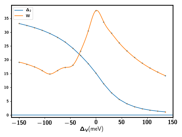
The bandwidth can be tuned by , as shown in Fig. 11.
A.1 Symmetry
First, there is time reversal symmetry which relates the two valleys: complex conjugation combined with where is the spinor index. Both Eq. 13 and Eq. 14 are also apparently invariant under rotation symmetry: where is the valley index and is spinor index in Eq. 13. There is no inversion symmetry (and therefore rotation symmetry) in Eq. 13 and Eq. 14.
Within the continuum model there is also a mirror reflection symmetry along the : where is the angle of in the polar coordinate. The Hamiltonian in Eq. 13 and Eq. 14 is invariant under the Mirror symmetry . However, microscopically this mirror reflection should be broken by the h-BN layer. We view it as a a good approximation in the continuum model.
A.2 Band Structures in a small out-of-plane magnetic field
The moiré superlattice folds the orginal band of TLG to a moiré Brillouin Zone (MBZ) which is a hexagon. We take both valleys of the original band to be the point of the MBZ.
We show band structures of the valence bands for TLG/h-BN system in a small out-of-plane magnetic field in Fig. 12 incorporating the effects of the valley Zeeman coupling.
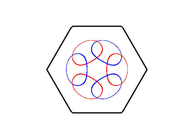
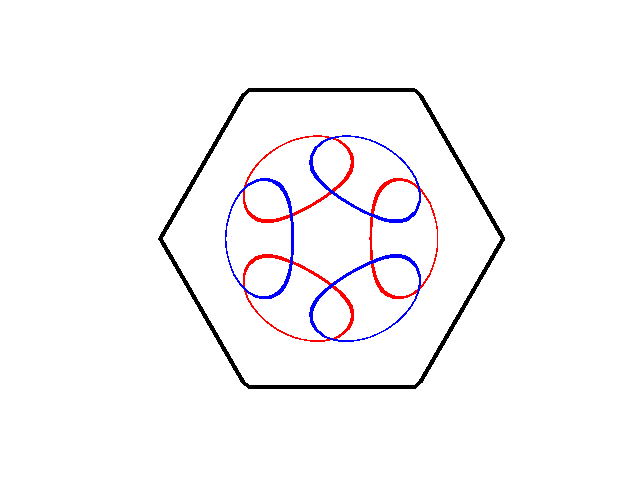
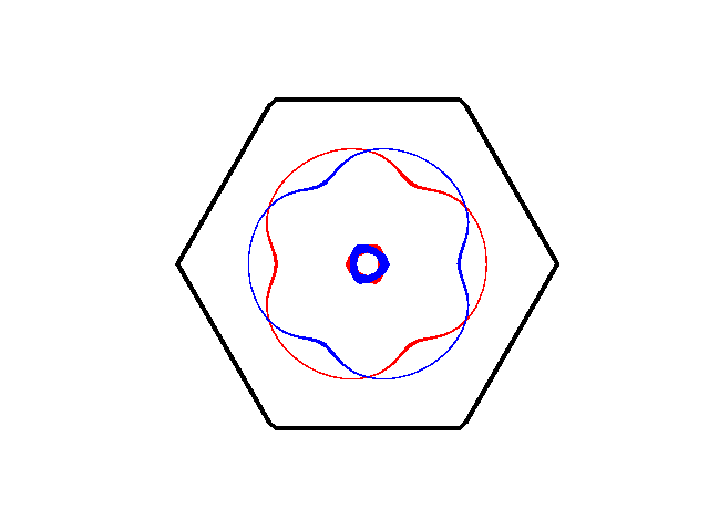
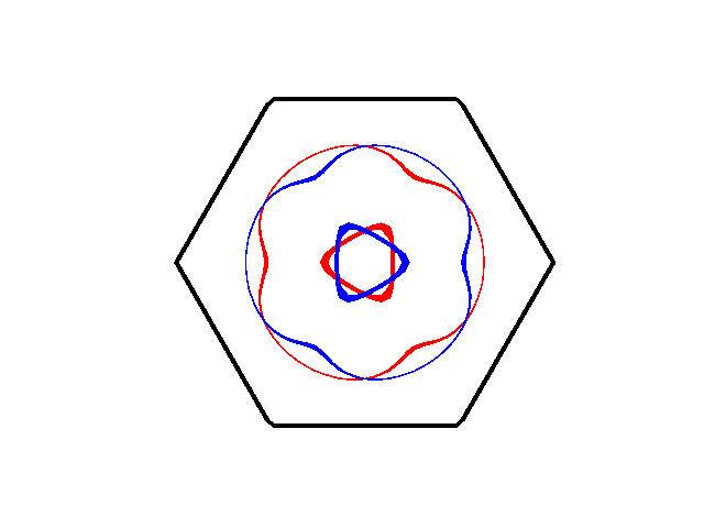
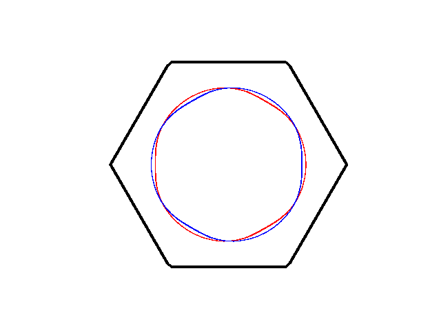
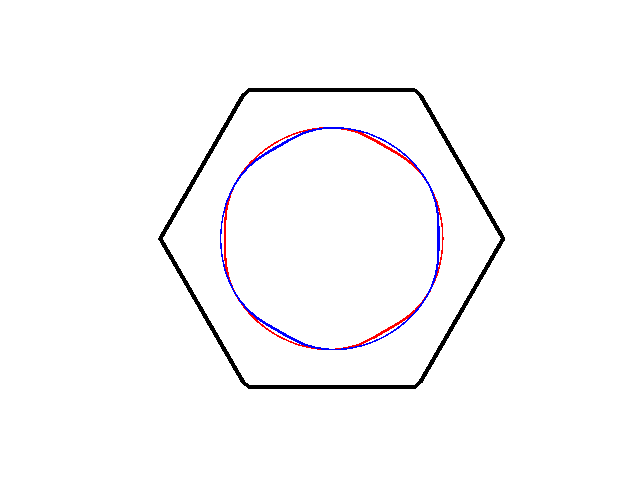
A.3 Fermi Surfaces at for
To aid the discussion of the metal-insulator transition for in the side, we provide the plots of the Fermi surfaces at several different values of in Fig. 13. In our model, the Fermi surfaces do not have an obvious nesting instability in the particle-hole channel. For , the filled Fermi sea has the topology close to meV.
Appendix B Hamiltonian In Momentum Space
In momentum space, we focus on the four valence bands labeled by spin and valley . The density operator projected to the valence bands is
| (15) |
where , nm is the lattice constant of the graphene layer. Form factors and can be calculated in the continuum model approach following Ref. Zhang et al., 2018.
The full Hamiltonian is
| (16) |
where we use screened Coulomb interaction . is the renormalized factor for dielectric constant. In this paper we use . is the screening length for which we use nm.
The first two terms of Eq. 16 have symmetry, which means that spin of each valley is separately conserved. The third term breaks it further down to . We expect this term is suppressed by a factor and therefore we only view it as a perturbation.
Appendix C Lattice Model for Side
For , the bands of both valleys are trivial(). Therefore there is exponentially localized Wannier orbital for each valley created by
| (17) |
can be obtained by the standard projection methoddMarzari et al. (2012): and . is the Bloch wave-function for valley . is an initial ansatz localized in real space. We choose to be the Fourier transformation of
| (18) |
where and is a constant vector corresponding to sublattices (which can be viewed as pseudospin degree of freedom and for simplicity we assume an ansatz for which the pseudospin is independent of ). The value of is chosen to optimize the overlap .
After getting , we can easily transform the Hamiltonian in Eq. 16 in terms of real space operator with forming a two dimensional triangular lattice. and .
For the kinetic term, we have
| (19) |
with
| (20) |
Similarly we can generate all of four fermion interactions. The second line in Eq. 16 gives
| (21) |
with
| (22) |
The dominant term is onsite and nearest neighbor Hubbard . The next order is Hund’s coupling, as shown in Eq. 6. There are also pair hopping and correlated hopping terms:
| (23) |
These terms meV, which is at the same order of Hund’s coupling term in Eq. 6. However, they involve onsite double occupancy, which should be suppressed by the much larger Hubbard . Therefore as a simplifying approximation we only keep Hund’s coupling term and ignore these correlated hopping and pair hopping terms.
Appendix D : Chern Bands
For , localized Wannier orbitals for each valley are impossible because of the non-zero Chern number. However, we can have a triangular lattice model with two orbitals per site at the cost that the valley operator can not be on-site. This kind of model was first discussed for the topologically non-trivial bands of the twisted bilayer graphene systemPo et al. (2018a).
We choose two initial localized ansatz and centered at a triangular lattice. They are related by the time reversal transformation. We label valley as . Then we calculate the following matrix: at each momentum point . This give the following two projected states:
| (24) |
where and is the annilation operator of the valley .
and create states which are not orthogonal and normalized. We define the following unitary matrix:
| (25) |
If we do Singular Value Decomposition: , then
| (26) |
Then we get Wannier orbitals:
| (27) |
It is easy to prove that and are normalized and orthogonal.
We can build our lattice models in terms of operators and where and are the unit vectors of the corresponding triangular lattice.
First for kinetic term, we have
| (29) |
where .
| (30) |
where are orbital indexes for each site. is valley index. are labels of triangular lattice sites.
We keep intra-orbital hopping and inter-orbital hopping . Other components can be generated by the time reversal transformation: , where while .
There is always the following symmetry and . The mirror reflection symmetry can not be kept explicitly in the current approach.
can not be implemented as on site operator in the Wannier orbital basis. Instead, we have
| (31) |
Again we have intra-orbital hopping and inter-orbital hopping . The symmetry requirement is: and . and follow from under time reversal.
Similarly to the case, four fermion interaction can be expressed in terms of Wannier orbital operator in real space:
| (32) |
where,
| (33) |
D.1 Result
We provide a two-orbital model for the bands following the procedure described above. For simplicity we ignore the trigonal warping term of Eq. 13 for the calculation of .
Tight binding parameters for and are listed in Table. 3 and in Table. 4 for meV. These tight binding parameters for a two orbital model can reproduce the two valence bands for each spin with Chern number .
| Comments | ||||||||
|---|---|---|---|---|---|---|---|---|
| A | A | A | A | on-site U | ||||
| A | A | A | A | nearest neighbor U | ||||
| A | A | A | A | correlated hopping | ||||
| A | A | A | A | inter-site Hund’s | ||||
| A | A | A | A | pair Hopping | ||||
| A | B | B | A | on-site U | ||||
| A | B | B | A | nearest neighbor U | ||||
| A | B | B | A | correlated hopping | ||||
| A | B | B | A | inter-site Hund’s | ||||
| A | B | B | A | pair Hopping | ||||
| A | B | A | B | |||||
| A | B | A | B | |||||
| A | B | A | B | |||||
| A | B | A | B | |||||
| A | B | A | B | |||||
| A | A | A | B | |||||
| A | A | A | B | |||||
| A | A | A | B | |||||
| A | A | A | B | |||||
| A | A | A | B | |||||
| A | A | B | A | |||||
| A | A | B | A | |||||
| A | A | B | A | |||||
| A | A | B | A | |||||
| A | A | B | A |
One can also write four fermion interactions in terms of these operators. We list the dominant interaction terms following the convention of Eq. 33 in Table. 5. The dominant term is still the on-site and the next-nearest-neighbor repulsion . For the side meV and is only one half of the value at the side. Meanwhile the inter-site Hund’s coupling and correlated hopping terms are at the order of instead of for the side. These are signatures of the Wannier obstruction. In the limit for integer fillings, we still expect an insulating ground state. These inter-site Hund’s coupling, correlated hopping and pair-hopping terms are much larger than the super-exchange terms and we expect the ground state is decided by these terms. However, the lack of the explicit valley index makes it hard to reliably deal with this lattice model. From Hartree Fock calculations in the momentum space Zhang et al. (2018) we expect the ground state to be valley polarized for . But we do not know how to understand this conclusion from the above lattice model.
Appendix E Spin-Valley model for side
For the side, to order , we derive a spin-valley model following the standard approach. There is already a Hund’s coupling in the four fermion interaction. Besides, at the order of we get the following super-exchange antiferromagnetic term:
| (34) |
where are valley indexes and are spin indexes. We use instead of to emphasize that they are neutral degrees of freedom which only carry spin and valley quantum numbers. is the phase in the nearest neighbor hopping for valley . From time reversal .
We label operator with Einstein summation convention. labels operator acting on the valley Hilbert space at site . Similarly labels .
For part, we use the following equation:
| (35) |
where terms like refer to tensor products.
Similar for part, we have
| (36) |
Then part gives
| (37) |
Similarly part gives
| (38) |
Summing the above four terms together, we get the spin-valley coupling from the super-exchange:
| (39) |
where the second and the third term break symmetry to .