A Hand Combining Two Simple Grippers to Pick up and Arrange Objects for Assembly
Abstract
This paper proposes a novel robotic hand design for assembly tasks. The idea is to combine two simple grippers – an inner gripper which is used for precise alignment, and an outer gripper which is used for stable holding. Conventional robotic hands require complicated compliant mechanisms or complicated control strategy and force sensing to conduct assemble tasks, which makes them costly and difficult to pick and arrange small objects like screws or washers. Compared to the conventional hands, the proposed design provides a low-cost solution for aligning, picking up, and arranging various objects by taking advantages of the geometric constraints of the positioning fingers and gravity. It is able to deal with small screws and washers, and eliminate the position errors of cylindrical objects or objects with cylindrical holes. In the experiments, both real-world tasks and quantitative analysis are performed to validate the aligning, picking, and arrangements abilities of the design.
Index Terms:
Hand design, assembly, grippers, precise grasping.I Introduction
The goal of this paper is to develop a robotic hand to pick up and arrange objects for assembly. Assembly is a classical problem to the robotics community. Researchers have studied the problem for decades and developed several solutions like compliant mechanisms and sensor-based close-loop control to perform assembly tasks. Using modern force sensors or well designed compliant mechanisms, assembly tasks could be performed with a high success rate.
On the other hand, the available solutions are relatively complicated and costly. They require high-quality force sensors and delicately designed mechanisms which might be unaffordable for middle and small manufacturers. Besides, especially for small objects such as nuts, washers, and screws which are not easy to grip, extra tools are needed. The extra tools impair the flexibility of an assembly system. For these reasons, we propose a novel hand design in this paper by combining an internal gripper, which is used to align objects and eliminate position errors, and an outer gripper, which is used for stable holding.
The goal of our design is as follows: 1) The gripper is expected to be able to generate large forces and hold objects stably. 2) The gripper is expected to have the ability to reduce the position errors of cylindrical objects or objects with cylindrical holes. 3) The gripper is expected to be able to pick and arrange small objects such as nuts, washers, and screws. 4) The gripper is expected to be simple in both mechanism and control. The proposed hand design satisfies these four requirements by combining two simple grippers.
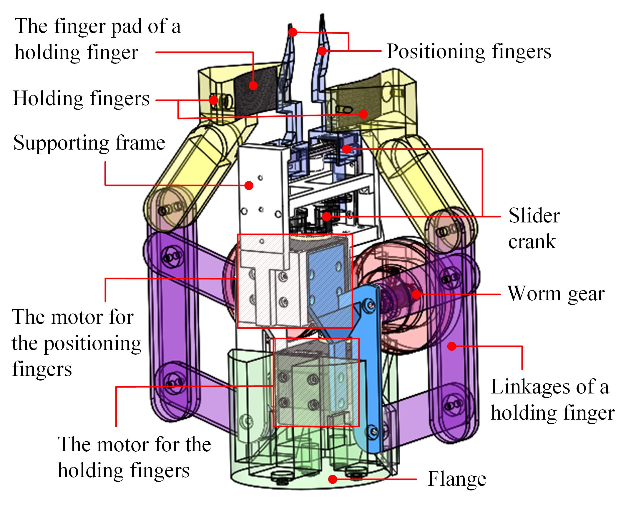
Fig.1 shows a sketch of the proposed design. In the inner part, there is a linear gripper driven by a slider-crank mechanism. The fingers of this gripper are thin and deliberately cut to align and arrange objects. In the outer part, there is a rotational gripper driven by a parallelogram. The gripper has two big fingers to exert large holding force. The rotational design of the holding gripper enables it to fold the fingers back when they are not used, and avoid conflict with the positioning gripper.
The positioning fingers could be used to eliminate the position errors of cylindrical objects or objects with cylindrical holes. It may grip cylindrical objects by closing the two fingers externally or grip objects with cylindrical holes by stretching the two fingers internally from the holes. The positioning fingers could also be used to pick up small objects like nuts and washers, and arrange screws by taking advantages of the geometric constraints from their delicately cut surfaces and gravity. The holding fingers are used to grasp objects stably after alignment.
In the experimental section, different objects and various tests are used to validate the aligning, picking, and arrangements abilities of the design. The holding forces of the outer gripper, and the aligning and arranging abilities of the inner gripper, are analyzed qualitatively, and the performance of a prototype is demonstrated with several real-world tasks.
The organization of the paper is as follow. Related work is presented in Section II. Details of the design are shown in Section III. Section IV explains the working strategies. Experiments and analysis are performed in Section V. Conclusions are drawn in Section VI.
II Related Work
The goal of this paper is to develop a simple robotic hand to align, pick up, and arrange objects for assembly. Thus, we review the literature related to gripper-based robotic hand design [1]. We present the related publications that have similar design goals or implemented similar functions.
For the work with similar design goals, Nishimura et al. [2] designed a gripper that can position and hold objects using a chuck clamping mechanism. The surface of their fingertips is carefully cut to generate tangential contact forces and push target objects to the hand center. Chen et al. [3] designed a gripper that can twist and re-positioning objects by combining linear motors and rotational motors. Hirata et al. [4] presented the design of fingertips to cage, align, and firmly pick up small circular parts like bearings, washers, and gears. The design is later used in real-world assembly tasks in [5]. More generally, Alberto et al. [6] proposed the design of finger shapes for 1DoF planar actuation, where he proposed a tool to transform the geometry contact constraints into an effector shape. Hsu et al. [7] used a self-locking underactuated mechanism mounted in parallel to actuators to firmly grasp objects. The self-locking is triggered automatically when the desired grasp is achieved. Without the self-locking mechanism, their hand design is similar to [8]. Harada et al. [9] proposed a gripper design with two shape adaptive mechanisms: A multi-finger mechanism to align objects and a granular jamming gripper to firmly hold objects.
For the work that implemented similar functions, Bunis et al. [10] designed a formationally similar three-finger gripper to cage and hold objects. The gripper has 1DoF. Together with their caging algorithms, the gripper can cage grasp with noisy poses and grasp it to a precise goal position. Zhang et al. [11] presented a gripper with reconfigurable jaw tips and a sequencer to align objects. The work is inspired by a previous work of Goldberg [12] which used a gripper with flat finger pads and some carefully designed work strategies for object alignment. Mason et al. [13] presented a picking system with simple grippers. The system can predicate the pose of a grasped objects by using some pre-learned knowledge. Wan et al. [14] developed a system that reorients an object from one placement to another by using a sequence of pick-ups and place-downs. Following the work, Cao et al. [15] used a vertical pin as the intermediate location for regrasping. Ma et al. [16] developed a dynamic simulator to generate stable poses and reorient objects by using them as intermediate states. Zhou et al. [17] presented a probabilistic algorithm that generated sequential actions to iteratively reduce the uncertainty of the objects. Dobashi et al. [18] used parallel grippers and grasp planners to align and prepare objects for assembly. The grippers used in these work are mostly simple parallel grippers with no special design. The working strategies helped to meet the functional requirements.
There are also designs that use sensors and feedback control to implement the desired functions. For example, Chen et al. [19] designed a parallel gripper with embedded vision and force feedback to adjust poses and perform insertion tasks. Golan et al. [20] developed a swivel mechanism to sense and position the surface of target objects. It is also an example of positioning using sensors.
Our paper biases on the design, and relies on the geometric constraints of the design and simple work strategies to implement the goal functions. Different from previous studies, our gripper comprises two simple grippers. The finger dimensions and shapes of the grippers, as well as their transmission mechanisms, are carefully formed to meet the required functions of aligning, picking, and arrangements. The working strategies for the gripper to eliminate position errors and arrange screws are implemented by taking advantages of the geometric constraints of finger shapes and gravity.
III Details of the Design
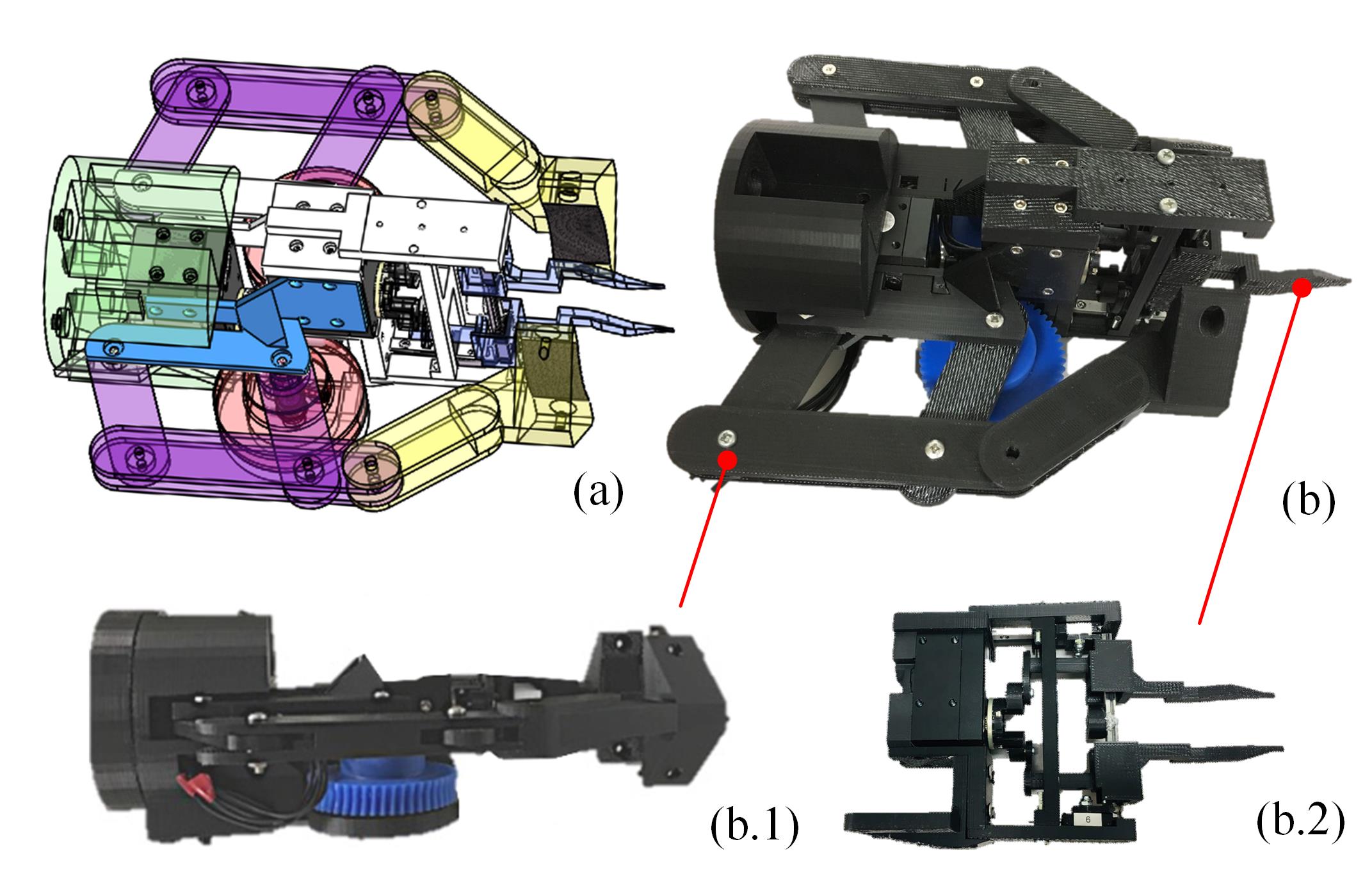
Fig.2 shows a prototype of the proposed design. The two grippers are perpendicular with each other. They have different purposes and are driven by different mechanisms. This section discusses the design details of the two grippers.
III-A The inner gripper
The details of the inner gripper are shown in Fig.3(a). Two fingers, mounted on a linear slide A, are driven by a Dynamixel XM430-W350 motor through a slider-crank mechanism (Fig.3(c)). With the help of this mechanism, the two fingers could move in parallel with each other.
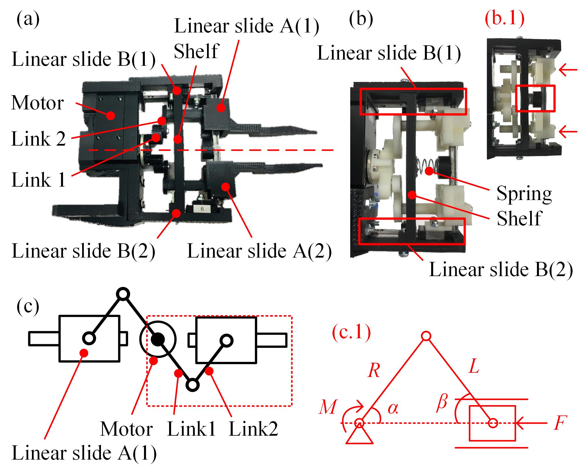
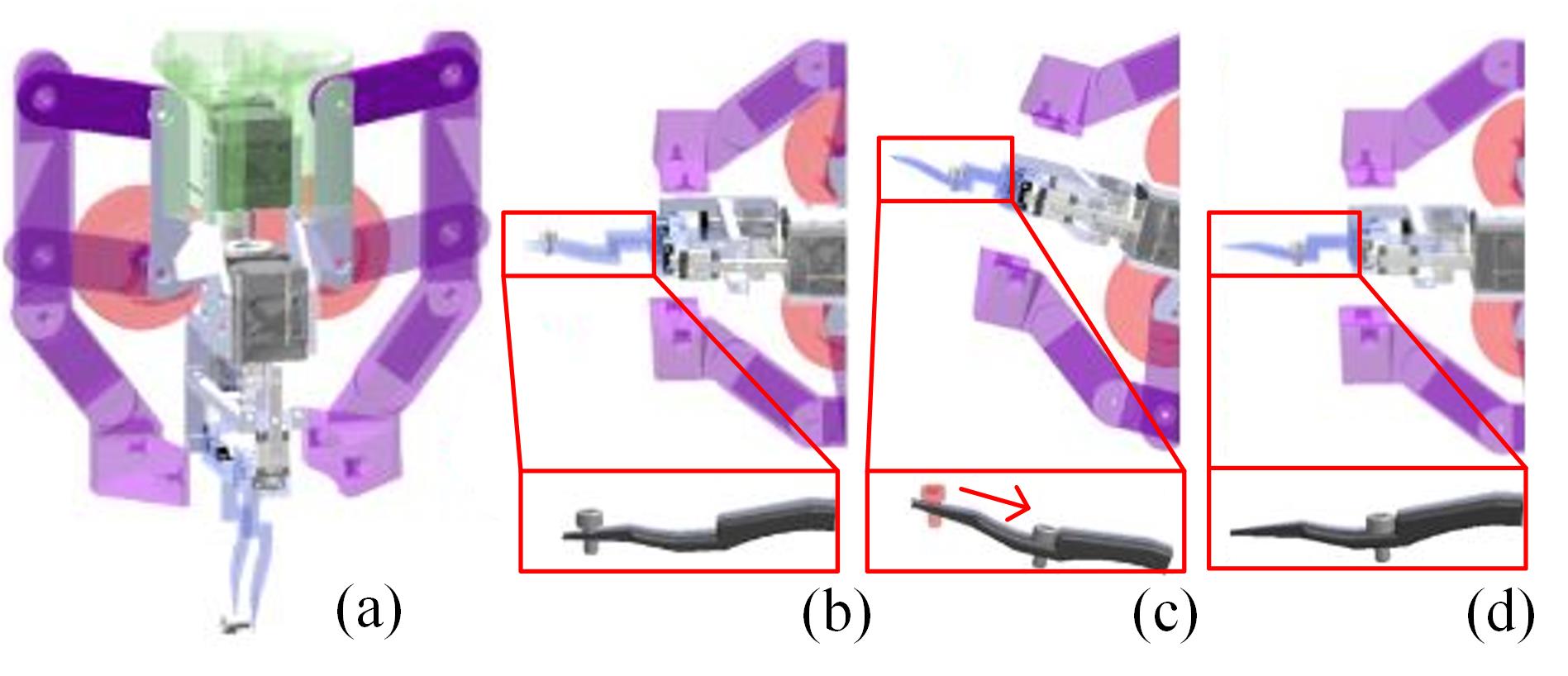
A compliant mechanism, as shown in Fig.3(b), is introduced to avoid hard conflicts with objects. Here, the slide A is guided by two horizontal linear slides B(1) and B(2) so that the fingers could retreat in the approaching direction in the presence of an resistance force. A shelf is installed between the linear slide A and the motor and a spring is attached to the shelf to help the fingers return to the initial position automatically when resistance forces disappear.
The joint between joint 1 and the slider is a peg-and-hole mechanism. The peg-and-hole mechanism secures the rotational motion between the two links. Meanwhile, it enables linear motion in the insertion direction, and allows the retraction of the fingers with the linear slide B. In contrast, the joint between Link 1 and Link 2 is connected using a bearing, since only rotational motion between the two links is needed.
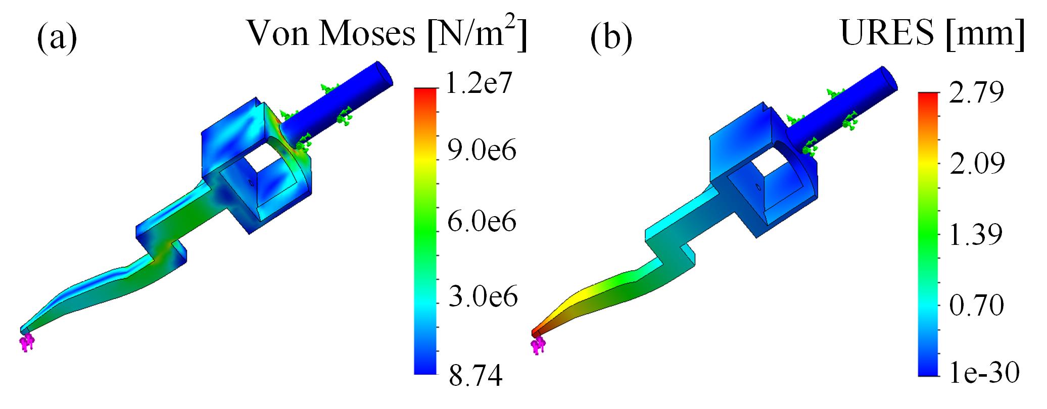
The shape of the positioning fingers is specially designed for arranging screws. The details will be discussed in the next Section. Also, the fingertips are cut into a tweezers shape for picking small objects and inserting into holes. The stiffness of the shape is validated by FEA (Finite Element Analysis). The results are shown in Fig.4. Here, the material is set to ABS. The cylindrical part of the shape is fixed as the boundary condition. As revealed by the results, the design is safe and has an acceptable deformation in the presence of a 3N force lateral force applied to the tips. The affordable force increases if the fingers were made by aluminum or steel.
The relation between the motor angle and the travel of a finger is formulated as:
| (1) |
In the prototype, , thus the relation between the motor angle and the travel of a finger is equal to:
| (2) |
The relation between the motor torque and the force exerted by a finger is:
| (3) |
The desired motor torque could be computed by the equation.
III-B The outer gripper
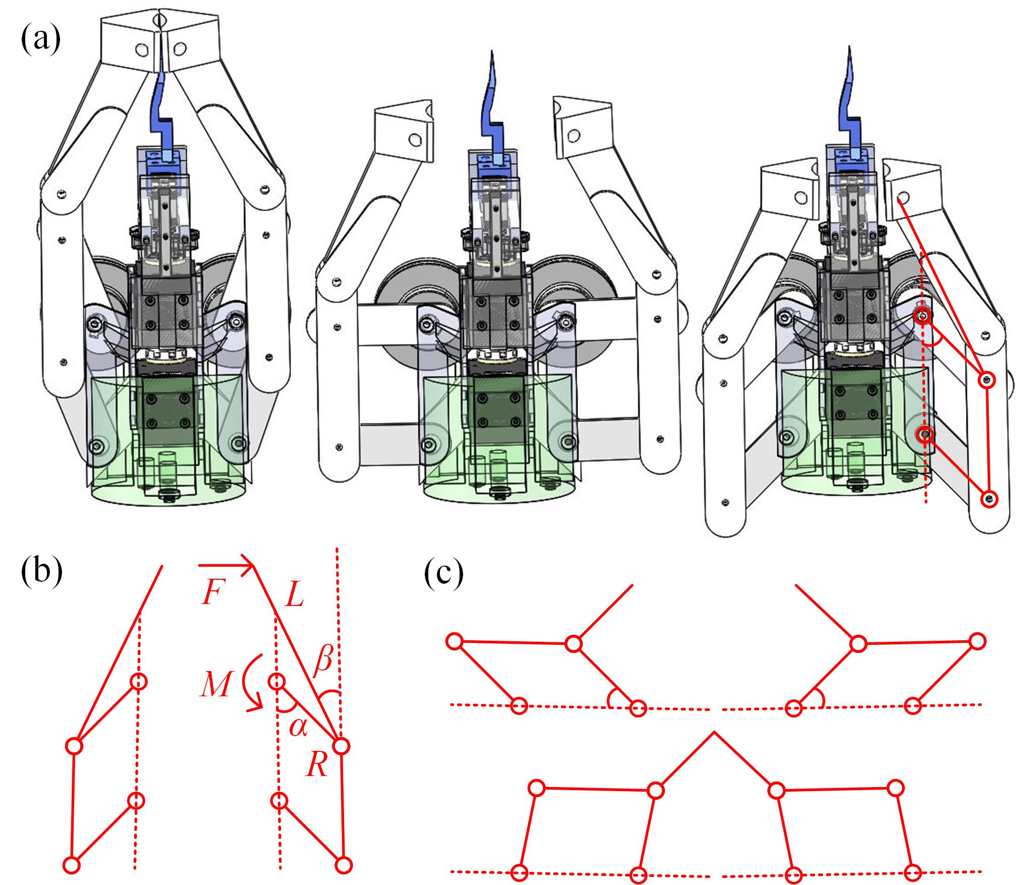
The outer gripper consists of two holding fingers, which are connected to a parallelogram driven by a motor and two worm gears. The parallelogram is arranged horizontally to allow the holding fingers fold back and avoid conflicts with the positioning gripper. Fig.5(a) and (b) respectively show the motion of the outer gripper and the kinematic structure of the horizontally arranged parallelogram. In contrast to Fig.5(b), Fig.5(c) shows a vertically arranged parallelogram. The vertically arranged one cannot fold the fingers back.
The relation between the motor angle and the travel of a finger is formulated as:
| (4) |
The relation between the motor torque and the force exerted by a finger is:
| (5) |
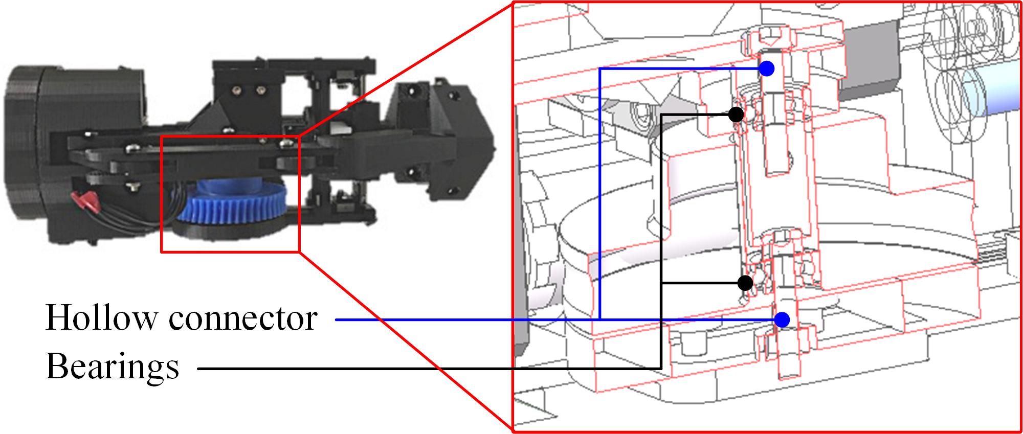
The worm gears are shown in Fig.6. The links connecting the worm gears are made hollow to increase the resistance to torsional forces. The motor motion is augmented and transmitted to the motion of the holding fingers through the worm gears.
IV Working Strategies
Strategies are designed to for the hand to align and pick up cylindrical objects with holes, cylindrical objects without holes, and arrange screws using its geometric constraints and gravity.
IV-A Cylindrical objects with holes
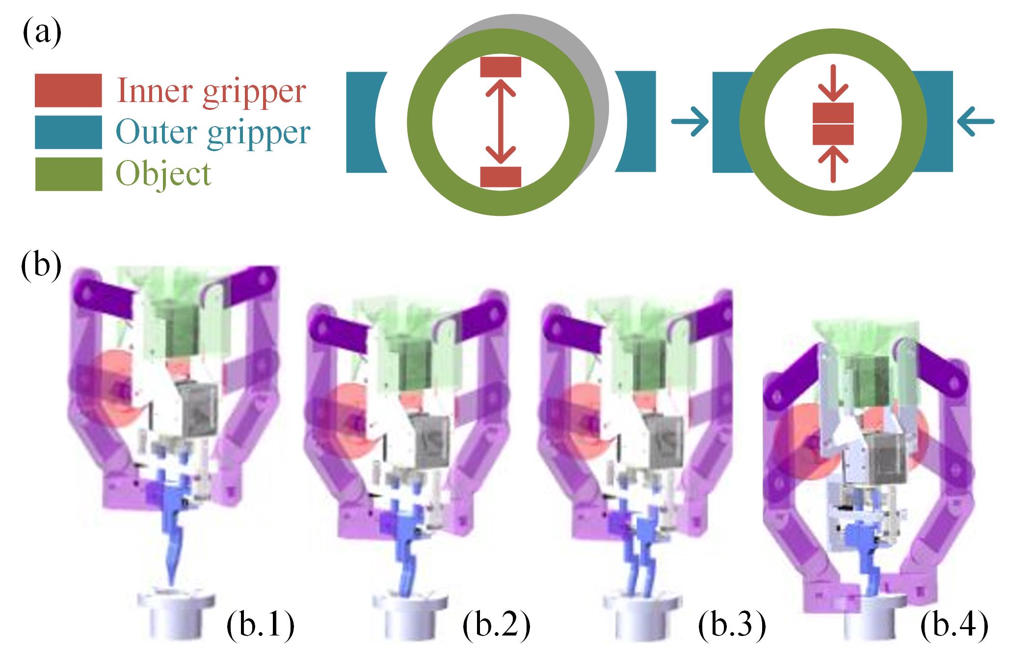
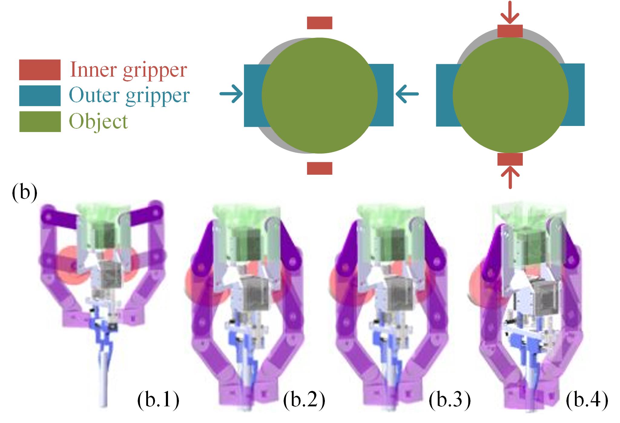
For cylindrical objects with holes, the working strategy is to use the positioning fingers as a stretcher. The flow of the working strategy is shown in Fig.7. It includes two steps. First, the fingertips of the closed inner gripper are inserted into the holes and stretch from the inner side to eliminate the position errors (see Fig.7(b.1-3)). Then, the holding gripper closes to grasp the object stably (see Fig.7(b.4)).
The stretching will be able to align an object under the following condition:
| (6) |
Here, is the tangential force. is the normal force. They are illustrated in Fig.8. The friction between object and ground is defined as where denotes the maximum static frictional coefficient and denotes the mass of the object. represents the maximum static friction coefficient between the object and the positioning fingers.
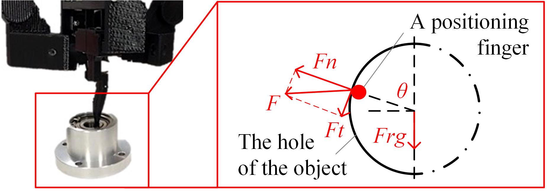
We assume an application where the mass of target objects are small and the materials are aluminum. In that case, can be neglected. When is approaching to 90 degrees, which is our goal, is always met and the condition in Eq.(6) can be satisfied with a high probability.
After alignment, the holding fingers close to grasp target objects stably. On the other hand, in the case of small objects with lightweight, the positioning fingers can stably hold the objects by stretching. The holding fingers are not used.
IV-B Cylindrical objects without holes
For cylindrical objects without holes, the working strategy is to alternatively close the outer and inner grippers. The positioning fingers are used as a squeezer, as shown in Fig.9. First, the holding fingers close with a relatively low motor torque to eliminate the position errors in the closing direction. Second, the positioning fingers close to eliminate the position errors of the object in a perpendicular direction. The object will be strictly aligned following the execution of the two consecutive and perpendicular grips. Third, the holding fingers close firmly to stably grasp the object.
IV-C Arranging screws
The screw arrangement is realized by taking advantages of the geometric constraints as well as gravity. The working strategy of arranging screws is shown in Fig.10. The flow includes four steps: 1) The hand picks up the screw using the positioning fingers. 2) The hand is tilted with an angle to the ground as it holds the screw. The value of will be discussed later. 3) The hand opens the positioning fingers with an additional distance so that the screw could drop and slide along the finger surface. The screw will slide into an end corner formed by the positioning fingers after this step. 4) The gripper is tilted back with - so that the positioning fingers are parallel to the ground. The screw will be posed vertically at the end corner of the positioning fingers after tilting back.
In order to let the screw slide along the positioning fingers. must meet the following equation.
| (7) |
The definitions of the various symbols are shown in Fig.11(a). indicates the interior angle of a fingertip. denotes the mass of a screw. denotes the Coulomb friction coefficient of the fingers. In the experiments, our target screws are M38 and M612 Allen screws. is therefore designed as 20∘.
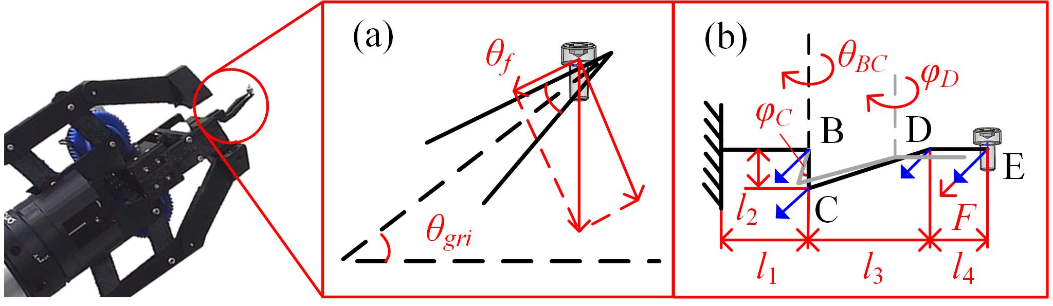
The deformation of the fingertips is taken into account to determine the additional opening distance . The finger is considered as a piece-wise beam shown in Fig.11(b). Its deformation includes a torsional deflection component and a bending deflection component, expressed as:
| (8) | ||||
Here, indicates the deformation along the opening direction at the fingertip E. is the torsional deflection component. Only BC bears the torsional deflection. is the bending deflection component. is the Young’s modulus of the material. is the second moment of area. is the modulus of rigidity of the material. is the diameter of the approximated beam at BC. The additional opening distance must be larger than the deformation . Meanwhile, it should be smaller than the diameter of a screw head. Thus, we choose = for the two Allen screws. This value could assure dropping and sliding, as well as avoid missing the screws. Subsequent to releasing the positioning fingers, the screws are guided by the finger shape to slide to an end corner.
The holding fingers are not used in screw arrangement. They are always folded back during the task so that another tool, for instance, a vacuum fastener could be used to pick up the screw from the top.
V Experiments
The experimental section is divided into two parts. First, different objects and various tasks are used to demonstrate the aforementioned abilities. Second, a quantitative analysis is performed to examine the proposed design.
V-A Real-world tasks
The experimental environment used for real-world executions are shown in Fig.12. The environment includes a UR3 robot, a 3D printed prototype of the gripper, and a task board. The task board requires attaching four objects, a washer, a pulley, a peg with a hole, and a solid peg, to some holes and shafts on it.

V-A1 Objects with holes
The peg with a hole, the washer, and the pulley, are objects with holes. Following the work strategy introduced in Section.IV, the hand will stretch the inner gripper in the hole to align the object, and then use the outer gripper to firmly grasp it. For smaller objects like the washer, the holding fingers are not used. The positioning finger could afford enough force to pick it up.
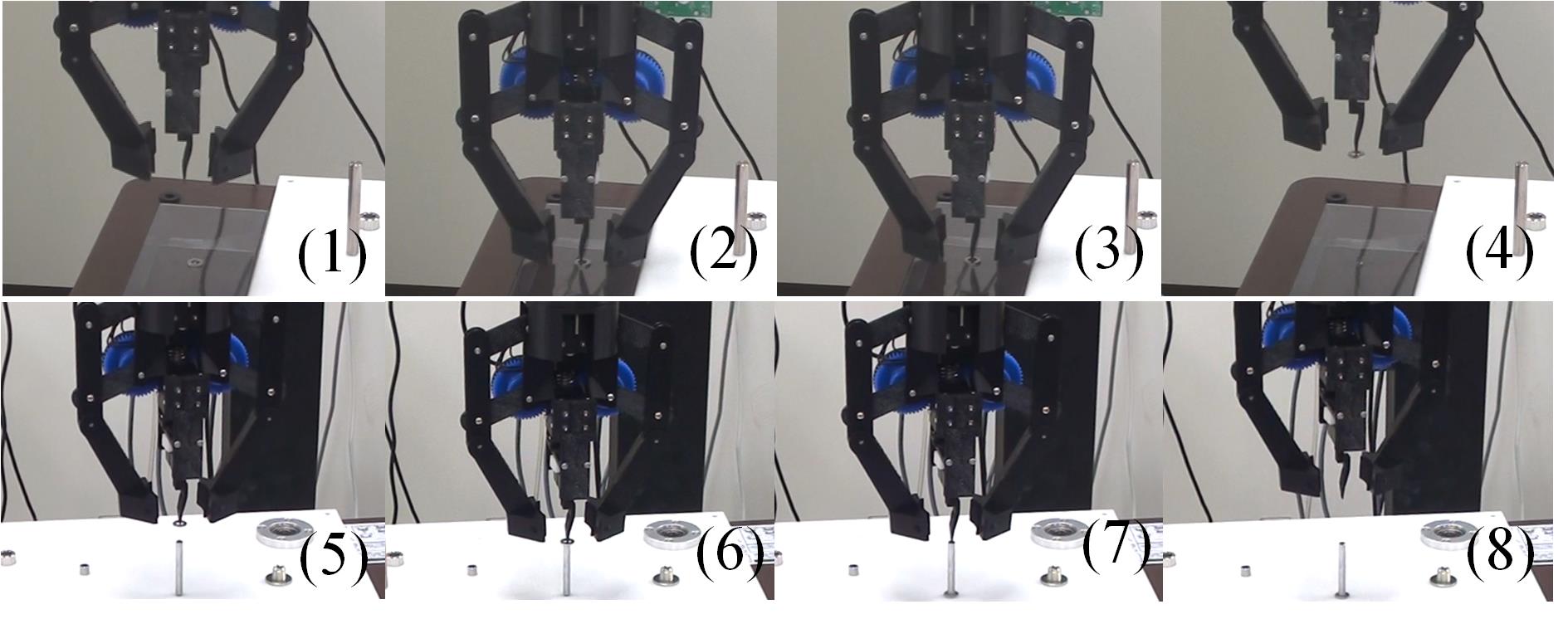
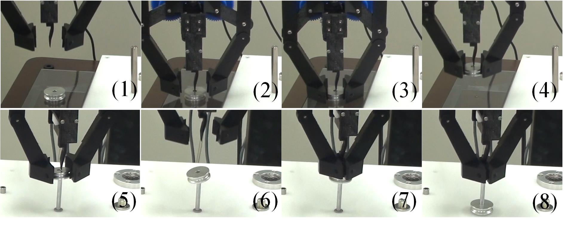
Fig.13 shows the manipulation sequences of these four objects. Fig.13(a) is the sequence of a peg with a hole. The object is aligned in Fig.13(a)(2-3) and picked up in Fig.13(a)(4-5). It is inserted into a hole on a task board in Fig.13(a)(6-8). With the help of the positioning fingers, the object could be successfully inserted into the hole without any visual feedback. Fig.13(b) shows the sequence of a washer. The washer is aligned and picked up in Fig.13(b)(1-4), and is attached to a peg on the task board in Fig.13(b)(5-8). Fig.13(c) shows the sequence of a pulley. The pulley is aligned by the positioning fingers in Fig.13(c)(1-2), is held and picked up in Fig.13(c)(3-4), and is attached to a peg in Fig.13(c)(5-6). An exception we found in the execution is large objects like the pulley tend to get stuck at a tilted pose. In that case, the holding fingers are used to push the object out of the stuck state, as is shown in Fig.13(c)(7-8).
V-A2 Objects without holes
The solid peg is the only object that does not have holes. Following the previously mentioned work strategy, the hand will close the outer gripper gently to eliminate the errors in the closing direction of the holding fingers. Then, it closes the inner fingers to eliminate the errors in a perpendicular direction. Finally, the holding fingers close firmly to stably grasp the object.
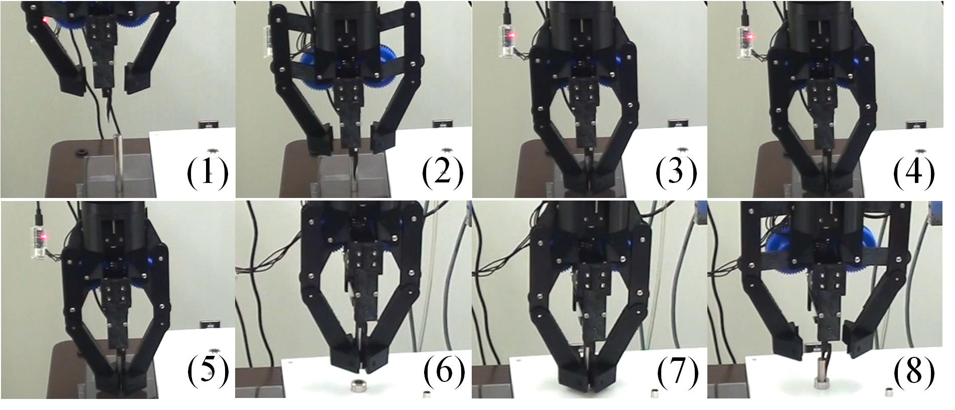
Fig.14 shows the execution sequence. First, the holding fingers eliminate the errors of the peg in the closing direction in Fig.14(3). Then, the positioning fingers eliminate the errors in a perpendicular direction in Fig.14(4). The peg is grasped firmly by the holding fingers in Fig.14(5), and is inserted into a hole on the task board in Fig.14(6-8).
V-A3 Screw arrangement
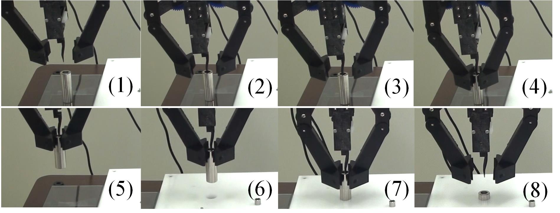
Besides the four objects discussed in the previous two subsections, the same robot and hand are further used to pick up and arrange screws. Following the work strategy presented in the Section.IV, the gripper picks up the screw using the positioning fingers, tilts and opens the fingers a bit to let the screw drop and slide to an end corner, and tilts back to the horizontal state to provide an upright screw to fastening tools like vacuum fasteners.
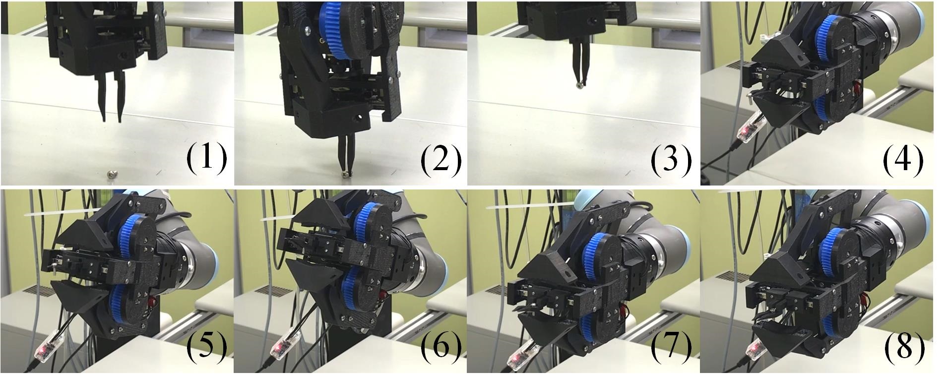
Fig.15 shows the execution sequence of screw arrangement. The screw is picked up by the positioning fingers in Fig.15(1-3). The hand tilts at Fig.15(4), opens a bit to let the screw drop and slide to an end corner in Fig.15(5-6), and tilts back to let the screw pose vertically in Fig.15(7-8).
V-B Quantitative analysis
Second, quantitative analysis is performed to examine the holding force of the outer gripper and the aligning and arranging abilities of the inner gripper.
V-B1 Holding force of the outer gripper
The method used to analyze the holding force of the outer gripper is shown in Fig.16. A Robotiq85 gripper, attached to a Robotiq FT300 F/T sensor and a UR3 robot, is used to pull an object out of the outer gripper. The outer gripper holds one end of the object. The Robotiq85 gripper holds the other end. The changes in forces along the pulling direction are measured to examine the maximum holding force.
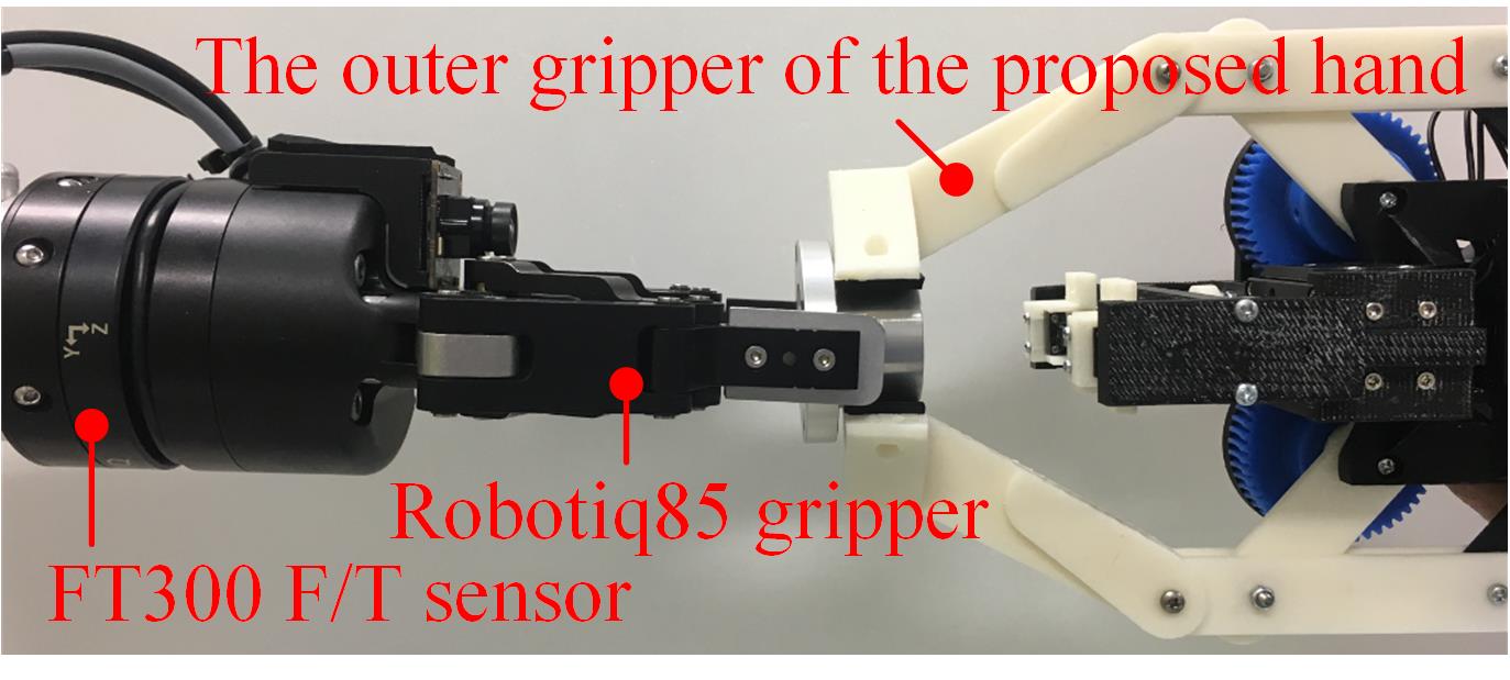
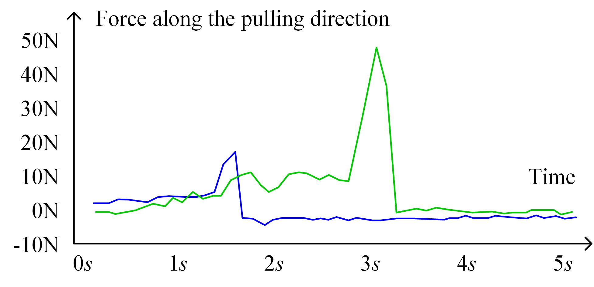
Fig.17 shows the changes of forces under two different torques exerted by the motor of the outer gripper. The blue curve is the result of a 1.67% maximum toruqeaaaThe worm gear has a 50:1 gear ratio. It is advisable to not use a large percentage of the maximum torque and avoid breaking the printed prototype.. The green curve is the result of a 3.34% maximum torque. The holding fingers could afford around 5 under 3.34% maximum motor torque, which is even larger than the maximum load of an UR3 robot (3).
V-B2 Aligning ability of the positioning fingers
In order to examine the aligning ability of the positioning fingers, we place target objects with at erroneous positions and use the hand to pick the object and perform peg-in-hole tasks. We measure the aligning ability of the positioning fingers by recording the success and failure of the peg-in-hole tasks.
The erroneous positions are manually selected as 16 evenly distributed positions on two concentric circles, as is shown in Fig.18(a). The center of the concentric circle is the correct position. The outer diameter of the concentric circle is D = . The inner diameter is d = .
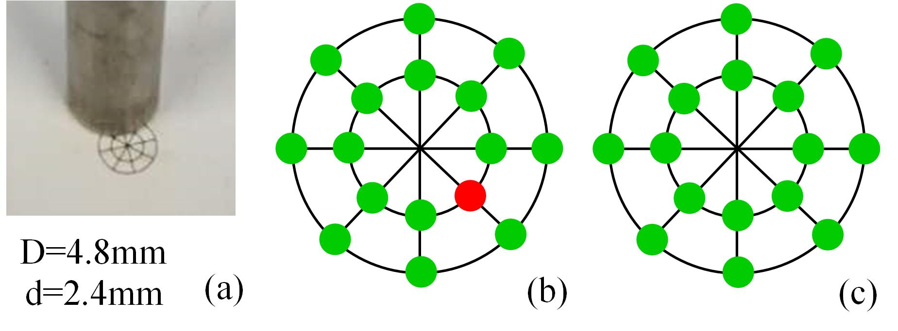
Fig.18(b) shows the results of an object with a hole. The dimension of this object is shown in Fig.12, 2_1. The green dots in Fig.18(b) indicate the hand successfully finished the peg-in-hole task when the object is placed at those erroneous positions. The errors at those positions are eliminated by the positioning fingers. The red dot indicates a failure. The results show that the finger may align 2.4 position error with high success rate. The precision is satisfying considering our low-quality 3D printer (ZORTRAX M300). Fig.18(c) shows the results of a peg without holes. All errors are eliminated in this case. The hand has better performance in eliminating the position errors of objects without holes.
V-B3 Arranging ability of the positioning fingers
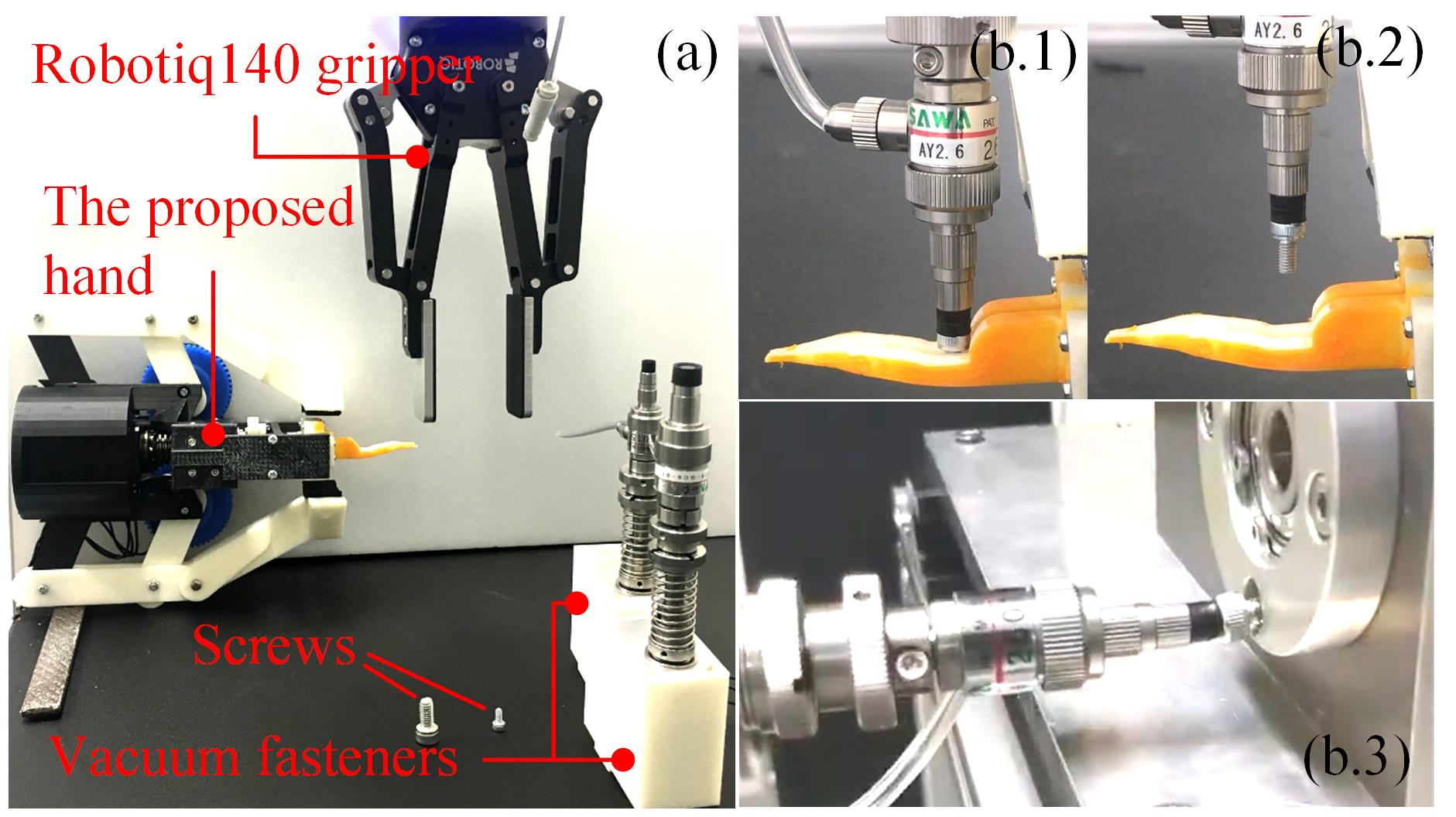
To test the arranging ability of the positioning fingers, we use a vacuum fastener shown in Fig.19(a) to pick up the arranged screws. Two types of screws, as is shown in the same figure, are tested. A Robotiq140 gripper is used to hold the vacuum fastener and pick up the screw from the top after arrangement (see Fig.19(b.1-2)). The picked screw is assembled to a bearing housing shown in Fig.19(b.3). In the experiments, we didn’t spot a failure. The arranging ability of the proposed hand is highly reliable, for at least the M3 and M6 Allen screws.
VI Conclusions and Future work
This paper presented a novel robotic hand combining two simple grippers to pick up and arrange objects for assembly. The design was validated by both quantitative analysis and various real-world tasks. The results show that the hand has large holding force, could eliminate position errors, could pick up and arrange small objects like washers and screws. The hand is simple in both mechanism and control and is expected to be used in practical systems in the future.
References
- [1] G. J. Monkman, S. Hesse, R. Steinmann, and H. Schunk, Robot gripper. Wiley, 2007.
- [2] T. Nishimura, M. Tennomi, Y. Suzuki, T. Tsuji, and T. Watanabe, “Lightweight, high-force gripper inspired by chuck clamping devices,” IEEE Robotics and Automation Letters, vol. 3, no. 3, pp. 1354–1361, 2018.
- [3] F. Chen, F. Cannella, C. Canali, T. Hauptman, G. Sofia, and D. Caldwell, “In-hand precise twisting and positioning by a novel dexterous robotic gripper for industrial high-speed assembly,” in Robotics and Automation (ICRA), 2014 IEEE International Conference on. IEEE, 2014, pp. 270–275.
- [4] Y. Hirata, A. Kaisumi, K. Yamaguchi, and K. Kosuge, “Design of handling device for caging and aligning circular objects,” in Robotics and Automation (ICRA), 2011 IEEE International Conference on. IEEE, 2011, pp. 4370–4377.
- [5] K. Yamaguchi, Y. Hirata, A. Kaisumi, and K. Kosuge, “Design of parts handling and gear assembling device,” in Robotics and Automation (ICRA), 2012 IEEE International Conference on. IEEE, 2012, pp. 2570–2577.
- [6] A. Rodriguez and M. T. Mason, “Effector form design for 1dof planar actuation,” in Robotics and Automation (ICRA), 2013 IEEE International Conference on. IEEE, 2013, pp. 349–356.
- [7] J. Hsu, E. Yoshida, K. Harada, and A. Kheddar, “Self-locking underactuated mechanism for robotic gripper,” in Advanced Intelligent Mechatronics (AIM), 2017 IEEE International Conference on. IEEE, 2017, pp. 620–627.
- [8] L. U. Odhner, L. P. Jentoft, M. R. Claffee, N. Corson, Y. Tenzer, R. R. Ma, M. Buehler, R. Kohout, R. D. Howe, and A. M. Dollar, “A compliant, underactuated hand for robust manipulation,” The International Journal of Robotics Research, vol. 33, no. 5, pp. 736–752, 2014.
- [9] K. Harada, K. Nagata, J. Rojas, I. G. Ramirez-Alpizar, W. Wan, H. Onda, and T. Tsuji, “Proposal of a shape adaptive gripper for robotic assembly tasks,” Advanced Robotics, vol. 30, no. 17-18, pp. 1186–1198, 2016.
- [10] H. A. Bunis, E. D. Rimon, Y. Golan, and A. Shapiro, “Caging polygonal objects using formationally similar three-finger hands,” IEEE Robotics and Automation Letters, vol. 3, no. 4, pp. 3271–3278, 2018.
- [11] M. T. Zhang and K. Goldberg, “Gripper point contacts for part alignment,” IEEE Transactions on Robotics and Automation, vol. 18, no. 6, pp. 902–910, 2002.
- [12] K. Y. Goldberg, “Orienting polygonal parts without sensors,” Algorithmica, vol. 10, no. 2-4, pp. 201–225, 1993.
- [13] M. T. Mason, A. Rodriguez, S. S. Srinivasa, and A. S. Vazquez, “Autonomous manipulation with a general-purpose simple hand,” The International Journal of Robotics Research, vol. 31, no. 5, pp. 688–703, 2012.
- [14] W. Wan, H. Igawa, K. Harada, H. Onda, K. Nagata, and N. Yamanobe, “A regrasp planning component for object reorientation,” Autonomous Robots, pp. 1–15, 2018.
- [15] C. Cao, W. Wan, J. Pan, and K. Harada, “Analyzing the utility of a support pin in sequential robotic manipulation,” in Robotics and Automation (ICRA), 2016 IEEE International Conference on. IEEE, 2016, pp. 5499–5504.
- [16] J. Ma, W. Wan, K. Harada, Q. Zhu, and H. Liu, “Regrasp planning using stable object poses supported by complex structures,” IEEE Transactions on Cognitive and Developmental Systems, 2018.
- [17] J. Zhou, R. Paolini, A. M. Johnson, J. A. Bagnell, and M. T. Mason, “A probabilistic planning framework for planar grasping under uncertainty,” IEEE Robotics and Automation Letters, vol. 2, no. 4, pp. 2111–2118, 2017.
- [18] H. Dobashi, J. Hiraoka, T. Fukao, Y. Yokokohji, A. Noda, H. Nagano, T. Nagatani, H. Okuda, and K.-i. Tanaka, “Robust grasping strategy for assembling parts in various shapes,” Advanced Robotics, vol. 28, no. 15, pp. 1005–1019, 2014.
- [19] F. Chen, K. Sekiyama, P. Di, J. Huang, and T. Fukuda, “i-hand: An intelligent robotic hand for fast and accurate assembly in electronic manufacturing,” in Robotics and Automation (ICRA), 2012 IEEE International Conference on. IEEE, 2012, pp. 1976–1981.
- [20] Y. Golan, A. Shapiro, and E. Rimon, “Object surface exploration using low-cost rolling robotic fingertips.” in HAPTICS, 2018, pp. 89–94.