CATCH-919 Hand: Design of a -actuator -DOF Anthropomorphic Robotic Hand
Abstract
To achieve human-like dexterity for anthropomorphic robotic hands, it is essential to understand the biomechanics and control strategies of the human hand, in order to reduce the number of actuators being used without loosing hand flexibility. To this end, in this article we propose a new interpretation about the working mechanism of the metacarpal (MCP) joint’s extension and the underlying control strategies of the human hand, based on which we further propose a highly flexible finger design to achieve independent movements of interphalangeal (IP) joints and MCP joint. Besides, we consider the hyperextension of fingertip into our design which helps robotic finger present compliant and adaptive posture for touching and pinching. In addition, human thumb muscle functions are reconstructed in the proposed robotic hand design, by replacing 9 human muscle tendons with 3 cables in the proposed task-oriented design, realizing all 33 static and stable grasping postures. Videos are available at https://sites.google.com/view/szwd.
I Introduction
The human hand has demonstrated tremendous dexterity in grasping and holding objects with various shapes. Many investigations suggest that such dexterity is highly related to the biomechanics of the human hand. Because of this reason, mimicking the biomechanical features of the human hand has long been considered as the gold standard for anthropomorphic hand designing in robotics. Developing such biomimetic hand is of significance to applications like prosthetics and industrial manufacturing, where the robotic hand is required to share similar, or even identical features as its human counterpart in the shape, structure, and function.

However, migrating the biomechanics of the human hand into its robotic replica is still demanding from the perspective of engineering. One research direction [1] in the anthropomorphic hand field follows the design of classical robot arm by embedding one motor into each hand joint for separated rotation control with simplified mechanical structure. Approximating the kinematics of the human hand in such direct motor-driven manner can effectively decouple motions of different joints and brings convenience for control policy design. Unfortunately, this method also introduces some problems like low payload due to micro-actuators and high energy loss because distal joint’s actuator becomes workload of proximal joint’s actuator, which further reduces the entire system’s load-bearing capacity. As so far, the soft hand appeals to many researchers working on grasping and manipulation due to its inherent compliance of soft materials and the consequent low control complexity [2]. A soft hand can carry large payload compared its self-weight [3] and achieve all independent controls of joints [4]. However, the soft hand may produce unwanted deformations due to its soft materials, and this will lead to imprecise control of in-hand manipulations. What’s more, the actuators in the aforementioned soft hands are pneumatic devices which are too big to be integrated into humanoid robots.
To solve above problems including low payload, the uncertainty of control and the large volume of actuators, we focus on designing cable-driven anthropomorphic hand in a fashion similar to human hand tendons. One primary benefit of employing such cable-driven design is that the actuators do not need to fit into the joint space, and thus they can be big enough to have sufficient load-bearing capacity and can be integrated into the robotic forearm like that of a human. However, compared with the motor-driven design, the cable-driven design usually requires many more actuators to achieve the same degrees of freedom (DOFs) in finger movement. In particular, the motor-driven design only needs one actuator to control the forward and backward rotations of a joint while the cable-driven method requires two actuators to control these two types of rotations separately. In order to reduce the actuator number without loosing flexibility, many cable-driven anthropomorphic hand developed, including Shadow hand [5], Yale openhand [6] and other recent designs [7, 8]. However, because most designers consider the actuator number as a priority in the mechanizing process, they discard some critical biomechanical features of the human hand, which undoubtedly leads to discrepancies between the real human hand and their proposed systems. Due to the lack of biomechanical features which are essential for human-like dexterity, these existing designs cannot achieve independent movements of every joint or they have to use more actuators compared with human tendons.
To explore potential biomechanical features and investigate neural control strategies of the human hand, the anatomically corrected testbed (ACT) hand [9] has developed through studying extensor mechanism [10], skeletal structure [11], kinematics of the thumb [12], variable moment arms for the index finger [13, 14] and for the thumb [15] to promote the similarity of their hand to human hands in anatomy. However, its internal joints are still connected by hinges and gimbals, which are incorrect anatomically and prevent robotic fingers from achieving the human-level dexterity. In particular, the finger joints are stabilized by the dense irregular connective tissue that is able to deform elastically. Thus, we cannot simply regard joints as fixed hinges or gimbals, especially for the saddle joint and condyloid variety of the thumb [16]. In order to preserve the joints’ biomechanics for the hand dexterity, a highly biomimetic anthropomorphic hand [17] replaced hinges and gimbals with artificial joint capsules, crocheted ligaments, and laser-cut extensor hood. However, their work focused on the mapping from cables to electromyography (EMG) signals and tele-operation, while how to explain the biomechanical advantages of the replicated joints remains a challenging problem.
In addition, all existing cable-driven anthropomorphic hands whose control strategies mimic humans still suffer from several limitations:
-
•
Joints cannot be controlled independently: Cable-driven design is difficult to decouple motions of joints. Although ACT hand [10] realized the function of independent control for metacarpal (MCP) joint, it still cannot control IP joints independently due to its incorrect anatomical position of interosseus [18] and obscure about the working mechanism of the MCP joint’s extension.
-
•
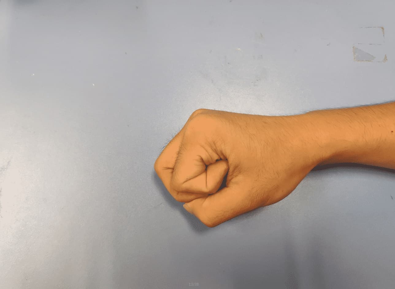
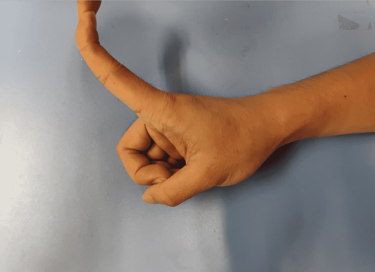
Without considering finger postures under external forces: Previous work did not consider the possible posture under the influence of external forces, and thus the existing cable-driven systems cannot respond to external forces in a compliant and adaptive manner as the human hand, which will lead to awkward postures in tasks like touching (as shown in the top right of Figure 1).
-
•
Web-like extensor mechanism is complex to replicate: Extensor mechanism is a web-like collection of tendinous material that help distal phalangeal and proximal phalangeal joints flex and extend simultaneously. This structure is troublesome and time-consuming to replicate into the anthropomorphic hand’s design by using the rubber design [17] or crocheted design [19].
-
•
Thumb cannot fit contact surfaces without pronation DOF: In previous work, the thumb has 4 DOFs which are sufficient for thumb’s fingertip to reach any point in 3-D plane. However, there is no additional DOF with rotational axis along the proximal or distal phalanx, but such DOF is essential for thumb to fit contact surfaces.
In our work, we focus on designing a Cable-driven Anthropomorphic Tendon-Controlled Hand with 9 actuators and 19 DOFs (CATCH-919 hand) whose index finger can be controlled independently for IP and MCP joints and achieve all possible postures with the consideration of the influence of external forces on the fingertip. The resulting hand design can pass all challenging tests defined in the GRASP taxonomy [20]. Our contributions can be summarized as follows:
-
•
Accomplish independent control for index finger joints: By understanding the working mechanism about MCP joint’s extension according to latest anatomical study, we propose a new interpretation about control strategies of human index finger within sagittal plane, which can solve the problem of independent control of index finger joints. The same technique can be also applicable for the independent control of middle, ring and little finger joints, which however is not necessary for accomplishing the grasping tasks in GRASP taxonomy [20] and thus is not implemented in our design.
-
•
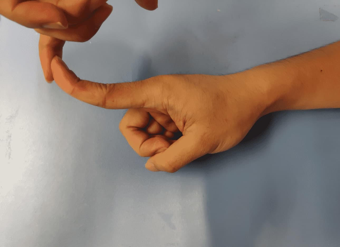
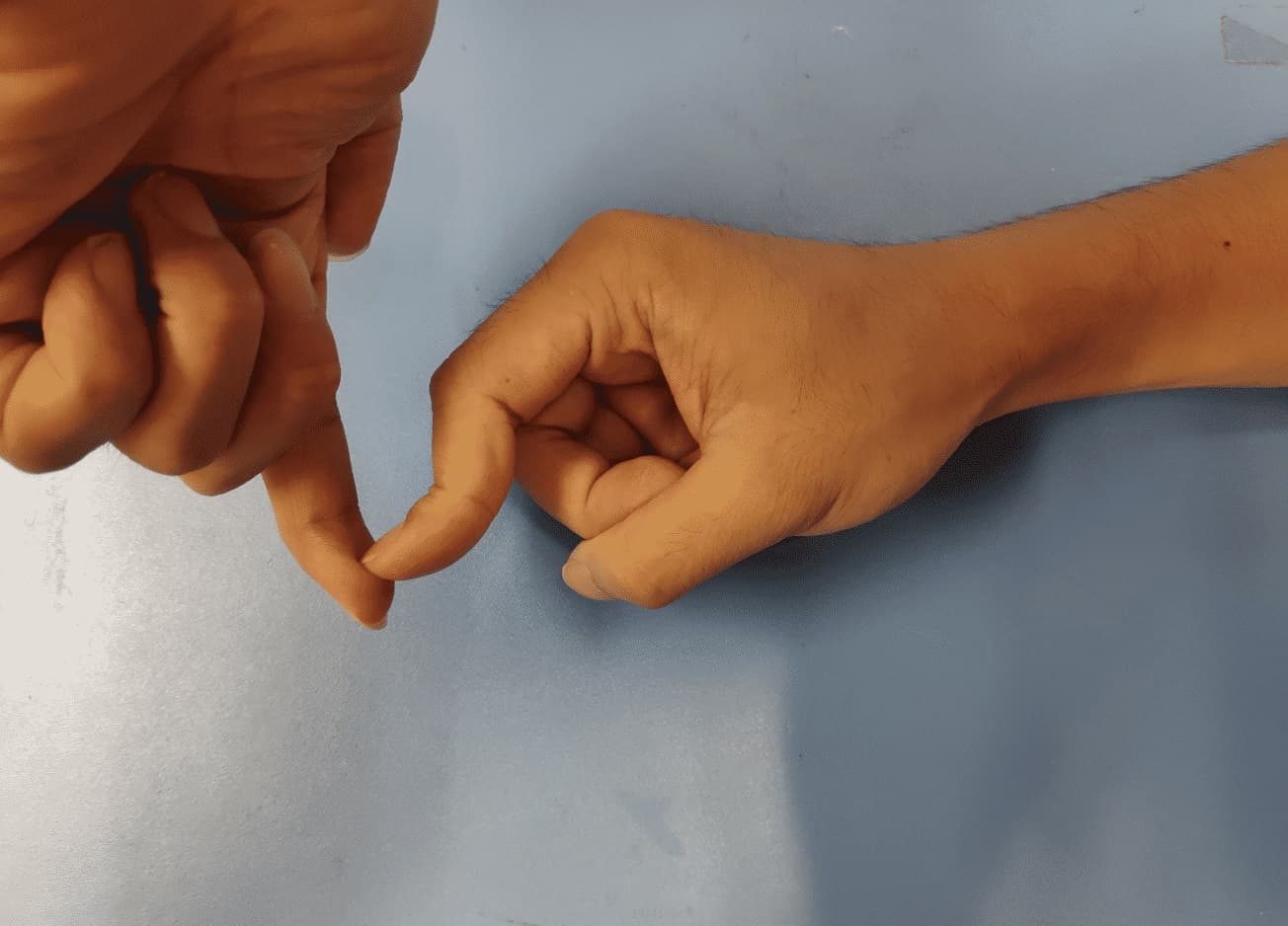
Consider finger postures under external forces in design: Our anthropomorphic hand can accomplish compliant posture for the touching task (as shown in the bottom right of Figure 1). Such improvement can effectively enlarge the contact area between the index fingertip and the touched object, which is crucial to make the fingertip sense more surface area and generate massive forces for the task.
-
•
A novel four-bar linkage to mimic extensor mechanism: We design a novel four-bar linkage to replace IP joints with a similar biomechanical feature of extensor mechanism which helps DIP and PIP joints flex and extend simultaneously [21]. This structure has clear kinematics and it is convenient to fabricate and assemble.
-
•
5-DOF thumb with 3 actuators by task-oriented design: In order to pass all challenging tests, we dismantle and combine muscles’ functions in the thumb and replace 9 human muscle tendons with 3 cables according to the task-oriented design. Our robotic thumb can use only 3 actuators to control 5 DOFs in steps while the thumb in the previous work [17] only has 4 DOFs with the same number of actuators.
II Control strategies of human index finger
The controversy about working mechanism of MCP joint’s extension in anatomy prevents researchers from figuring out control strategies of human hand. In this section, we will discuss two different mechanical structures of the index finger according to the classical anatomical theory and the latest medical research to propose a new interpretation about control strategies for achieving independent control of IP and MCP joints. We also interpret the muscle activation when fingertip is extended by external forces, which is not considered in the previous work about anthropomorphic hand.
II-A Index finger illustration
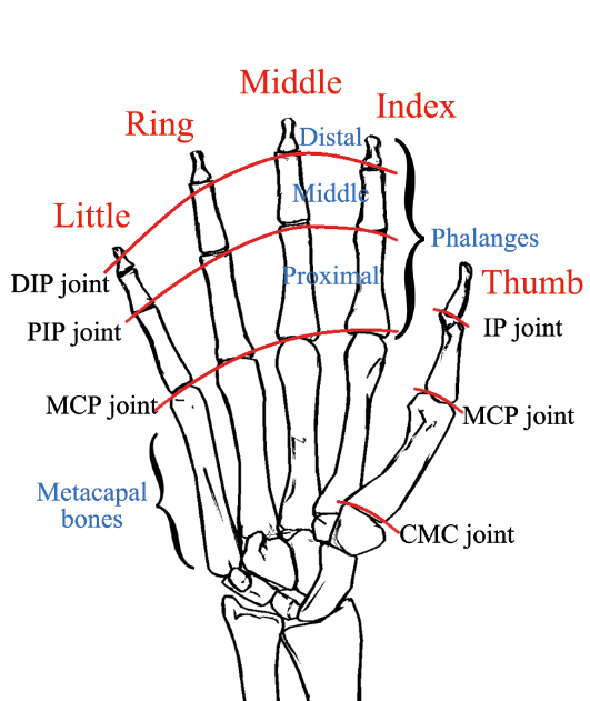
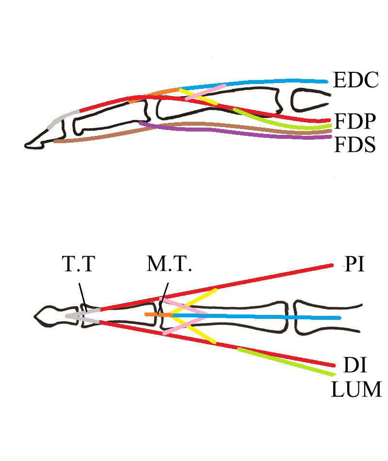
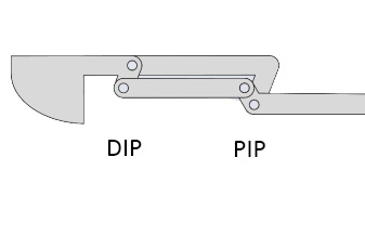
As shown in Figure 2(a) and Figure 2(b), the index finger has three joints which are called distal interphalangeal (DIP) joint, proximal interphalangeal (PIP) joint, and metacarpal (MCP) joint respectively and it is controlled by 7 muscles: flexor digitorum profundus (FDP), flexor digitorum superficialis (FDS), lumbrical muscle (LUM), 2 interossei including palmar interosseous muscle (PI) and dorsal interosseous muscle (DI), extensor digitorum communis (EDC), and extensor indicis (EI). But EI does not exist in other fingers and it only strengths the independent ability to extend the index finger [22]. As a result, we omit this muscle in our following research.
Among these muscles, FDP is inserted in the palmar base of the distal phalanx and its primary function is to flex DIP, PIP and MCP joints. FDS is inserted in the palmar base of the middle phalanx and primarily a flexor of PIP and MCP joints. EDC is connected with an extensor mechanism that is inserted on dorsal sides of distal and middle phalanges, and its main role is to produce extension of MCP joint. It also helps to extend both PIP and DIP joints. However, the main extensors of these joints are the interossei (PI and DI) and lumbricals (LUM), which also help to prevent the hyperextension of MCP [23]. Biomechanical studies have shown that interossei (PI and DI) is more essential for IP joints’ extension and MCP joint’s flexion than lumbrical (LUM) [24, 25]. And the full of muscle spindles in lumbricals suggests that their main function is for the proprioceptive perception of the fingers rather than for the motion control [26]. Hence, the human index finger accomplishes the sufficient flexibility and dexterity of 4 DOFs (3 flexion/extension and 1 abduction/adduction) by using only 5 tendons (i.e., FDP, FDS, EDC, PI, DI, but without LUM) along with the extensor mechanism which helps DIP and PIP joints flex and extend simultaneously (as shown in Figure 2(c)).
II-B Working mechanism of MCP joint’s extension
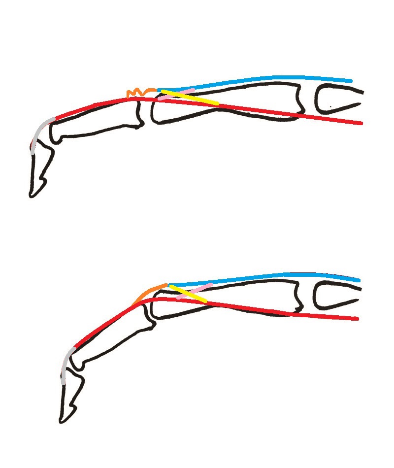
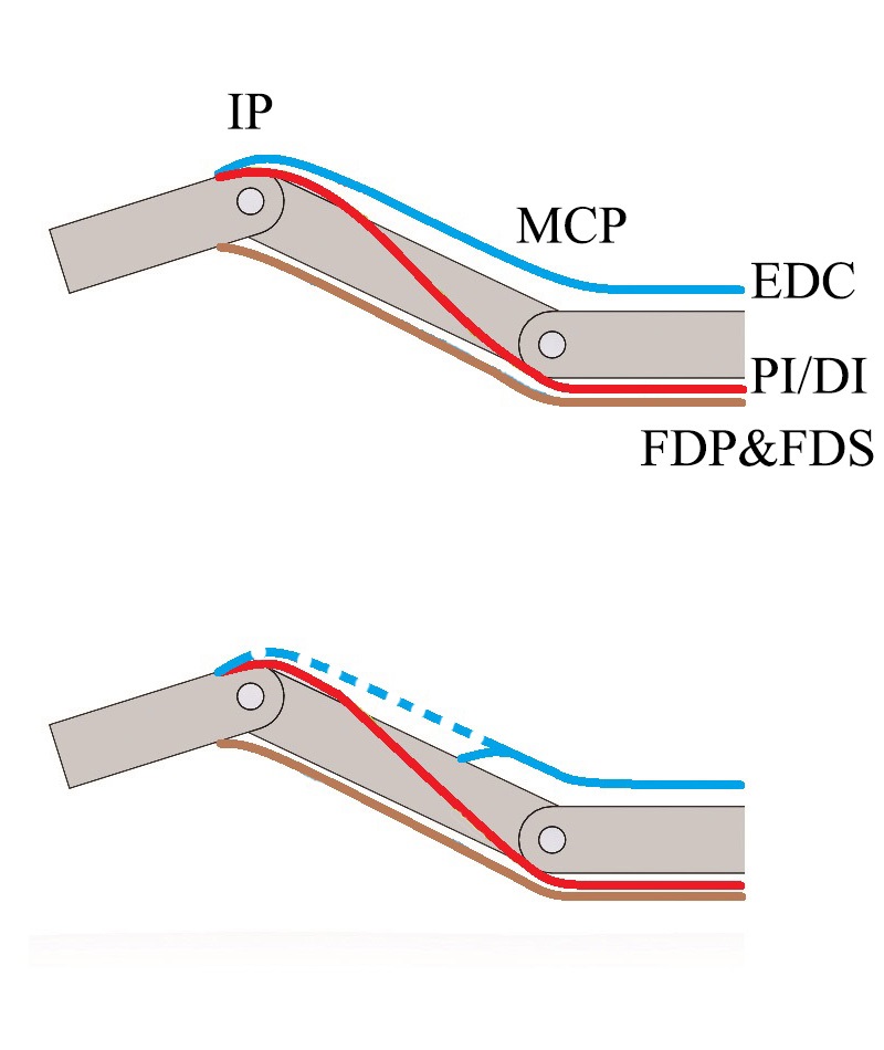
Till now, the MCP joint’s extension principle remains to be a controversial topic in anatomy, and a set of different explanations have been proposed. Some early work believed that the small deep slip of EDC tendon, which is inserted in the proximal phalanx, plays an important role in MCP joint’s extension. However, anatomical and radiological studies have proven that such small deep slip is inconsistent and lax at all functional MCP joint positions and thus is functionally inessential for MCP joint’s extension [27]. Another explanation widely accepted nowadays is that the MCP joint’s extension is accomplished via the sagittal bands which, acting as a sling or lasso, attach the extensor tendon to the base of the proximal phalanx [28]. However, this statement rarely has any reference and is also challenged recently by [29], which concluded that the torque passing from the dorsal side of the middle phalanx by EDC tendon’s tightening is the main factor for the MCP joint extension. The new structure proposed in [29] is also not accurate from the perspective of force analysis. To explain this, we illustrate the index finger movement within sagittal plane according to this work in the top of Figure 2(d). Note that here we regard PIP and DIP joints as one joint when studying the MCP joint movement, because both joints will flex simultaneously due to the extensor mechanism when flexors contract. However, when flexors contract (i.e., the brown line in the top of Figure 2(d)), it is difficult to only rotate IP joint and use EDC to keep MCP joint stable from the perspective of force analysis. As a result, this structure cannot fully explain the independent movements of IP and MCP joints. ACT hand [10] also used the same structure to interpret their robotic finger movement. However, their interossei does not always stay in the palmar side of MCP joint, which is not anatomically correct [18]. Although their cable control strategies can achieve all static postures like human hand, they still cannot solve the independent control of IP joints on the course of dynamic finger motion.
From the aforementioned force analysis, we conclude that the main tension from EDC tendon should be exerted on proximal phalanx directly, and thus the independent control of IP and MCP joints can be achieved using structure shown in the bottom of Figure 2(d). Note that here we ignore the tension influence of the DIP and PIP joints through EDC tendon (the dash line in Figure 2(d)), because such function is not significant. In the following part, we will use this new model to analyze the mapping from human hand’s postures to muscle activation within sagittal plane.
II-C Mapping from postures to muscle activation
In sagittal plane, the finger postures without the influence of external forces can be categorized into 5 types as shown in Figure 3: (a) is neutral position where no muscle is activated. (b) represents MCP joint’s hyperextension111hyperextension: https://www.youtube.com/watch?v=NQWifmm_qf4 or extension and IP joints’ extension. (c) represents MCP joint’s hyperextension or extension and IP joints’ flexion. (d) represents MCP joint’s flexion and IP joints’ extension. (e) represents MCP joints’ flexion and IP joints’ flexion. The finger postures when the external force is exerted on the palmar side of fingertip and DIP joint stays in hyperextension state can be divided in 3 classes as shown in Figure 3: (f) represents the case when no muscle is activated. (g) represents PIP joint’s extension no matter which MCP joint angle is. (h) represents PIP joint’s flexion no matter which MCP joint angle is. Their mapping from postures within sagittal plane to muscle activation can be expressed in Table I where indicates that the corresponding muscle is activated. FDP’s means that this muscle can be activated for resisting large external forces and EDC’s indicates that this muscle can be activated to stabilize the MCP joint at any desired degree.
| Posture | Description | Muscle | ||||
| FDP | FDS | PI/DI | EDC | |||
| Figure 3(b) | without external forces | MCP joint’s (hyper)extension and IP joints’ extension | + | + | ||
| Figure 3(c) | MCP joint’s (hyper)extension and IP joints’ flexion | + | + | + | ||
| Figure 3(d) | MCP joint’s flexion and IP joints’ extension | + | + | + | (+) | |
| Figure 3(e) | MCP joint’s flexion and IP joints’ flexion | + | + | (+) | ||
| Figure 3(g) | under external forces | PIP joint’s extension and any MCP joint’s angle | (+) | + | + | |
| Figure 3(h) | PIP joint’s flexion and any MCP joint’s angle | (+) | + | |||
III Development of our Robotic Hand
As shown in Figure 4(a), in our design, every finger has 3 DOFs for flexion/extension except that the index finger has one more DOF to abduct/adduct, thumb has two more DOFs for abduction/adduction and pronation respectively, and the palm has an underactuated DOF that relies on ring and little fingers’ flexion. In total, 9 Feetech servos222Feetech servo: http://www.feetechrc.com/ (SCS40, ) are used for controlling the finger movements: 1 for ring and little fingers, 1 for the middle finger, 4 for the index finger and 3 for the thumb.
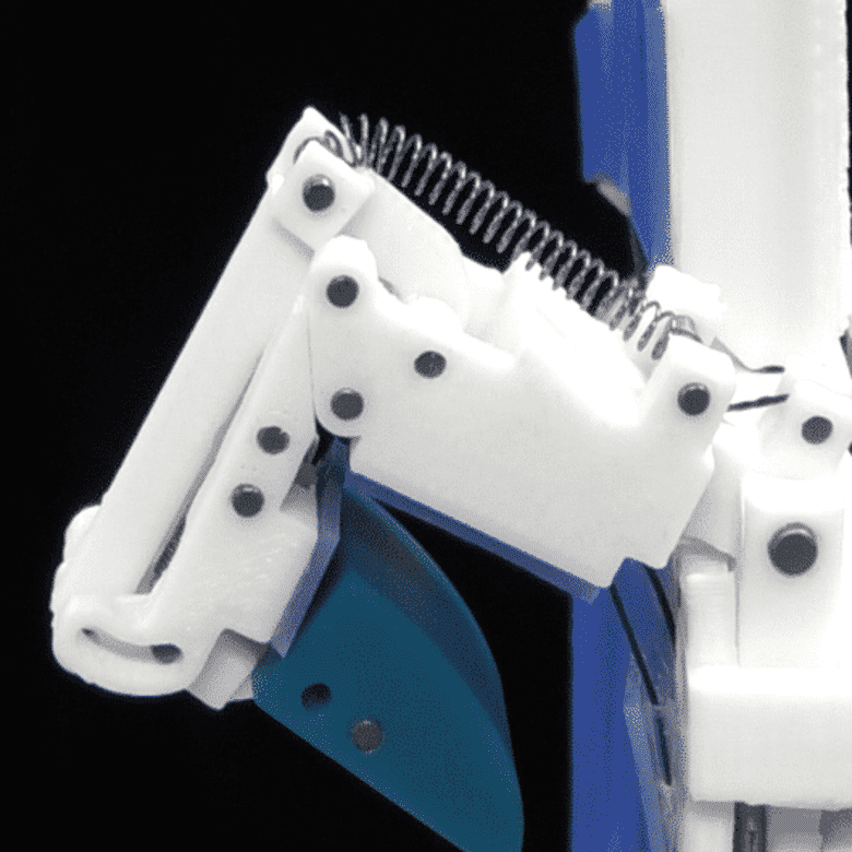
III-A Design of index IP joints
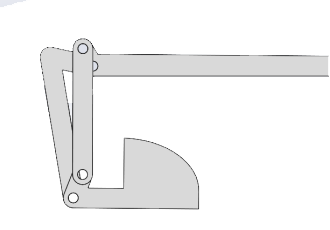
We replace the IP joints in the human hand by a novel four-bar linkage, which mimics the biomechanical feature of extensor mechanism in terms of enabling DIP and PIP joints flex and extend simultaneously. The four-bar linkage structure is illustrated in Figure 5. Note that the simultaneous flexion and extension of DIP and PIP is the only biomechanical advantage of extensor mechanism with sufficient anatomical support. Other biomechanical advantages such as the gliding mechanism introduced in [17] are not supported by sufficient evidence from the anatomical perspective [21]. Thus, according to our knowledge, our design does not sacrifice the biomechanical features that have been verified till now.
To increase index finger’s flexibility, we also consider how to realize the passive hyperextension of the DIP joint. This is an problem rarely touched in the cable-driven anthropomorphic hand community, but it is very important for pinching and touching tasks. In our design, we only consider the hyperextension of the DIP joint, because even though the human finger’s PIP joint has hyperextension, its angle is very small compared with DIP joint. In addition, this design can also provide a more clear kinematics.
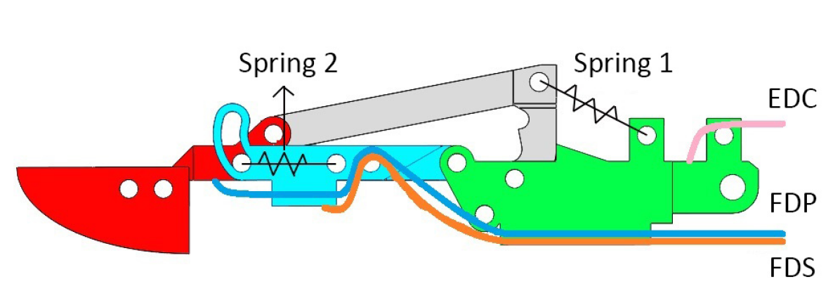
The whole design of IP joints is shown in Figure 5(c). The red region is the distal phalanx, the light blue region is the middle phalanx, and the green region is the proximal phalanx. Spring 1 implements the interossei’s passive musculotendinous resistance to maintain PIP joint at 0 degree. Spring 2 connects distal and middle phalanges and implements FDP’s passive musculotendinous resistance to maintain DIP joint at 0 degree. If fingertip’s palmar side is carrying out an external force, it can extend along sliding chute, which is located in the distal side of light blue area.
III-B Design of the index MCP joint
Although interossei can control the finger’s abduction and adduction, it also influences the flexion of MCP joint and extension of IP joints. If we still use cable-driven mechanism in our anthropomorphic hand for abduction/adduction, the precise control of the finger would be difficult, because the lack of somatic sensation feedback as the human skin [30], which may result in unstable control. Hence, we use motor-driven design in the MCP joint for adduction/abduction directly and use the spring to implement the interossei’s influence within sagittal plane, as shown in Figure 5(c).
III-C Design of the thumb finger
From the geometric perspective, if a thumb wants to reach anywhere within a ring in the 2-D plane, it needs 2 joints; if it wants to change its terminal to any angle, it needs 3 joints in the 2-D plane; if it wants to reach anywhere in the 3-D plane on the basis of 3 joints before, it need one extra joint that is orthogonal to first three joints. But in order to better fit surfaces of other fingertips, the thumb needs a fifth degree of freedom that is orthogonal to other four joints. Thus, it is necessary to have at least 5 DOFs to ensure sufficient flexibilities for the thumb: 3 flexion/extension DOFs, 1 abduction/adduction DOF, and 1 pronation/supination DOF.
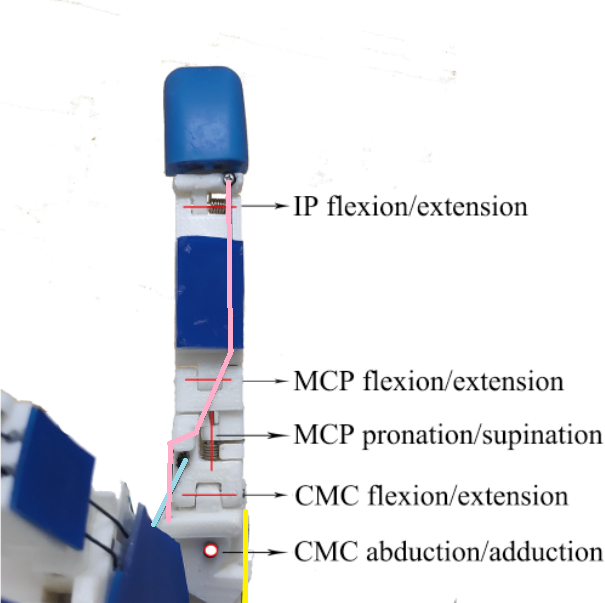
The human thumb has three joints as shown in Figure 2(a). Among these joints, the carpometacarpal (CMC) joint is commonly explained as a saddle joint [16] which is responsible for 1 flexion/extension DOF and 1 abduction/adduction DOF. Although the CMC joint has curved axis that allows rotation, sliding, translation, and pivoting motions [31], we discard this biomechanical feature because its precise locations of joint axes are still controversial. The MCP joint of the thumb is a condyloid variety. Like every condyloid joint, it has two DOFs for flexion/extension and abduction/adduction. However, as a result of its complex biomechanics, it has a third DOF (pronation/supination) allowing axial rotation of the proximal phalanx, which is essential for thumb opposition [16]. To accomplish simpler kinematics, better control and more convenient assembly, we treat the CMC joint as a fixed 2-DOF universal joint for flexion/extension and abduction/adduction. For the MCP joint, we only reserve 1 flexion/extension DOF implemented using the hinge and 1 pronation/supination DOF implemented with the help of a small torsional spring, as shown in Figure 4(b).
The human thumb has 9 motor muscles to achieve its great mobility and dexterity. However, it is unnecessary for our robotic thumb to assemble the same number of actuators according to the task-oriented design because we do not need the robotic thumb to accomplish very delicate movements. To reduce the actuator number, we use springs to keep robotic thumb in extension state in order to save 3 extensors, including abductor pollicis longus, extensor pollicis brevis, and extensor pollicis longus. Then we reconstruct the remaining 6 muscles’ functions in the thumb and design 3 cables’ layout as shown in Figure 4(b). Among these wires, the yellow line is responsible for CMC joint’s abduction. The light blue line is responsible for CMC joint’s adduction and then CMC joint’s flexion if CMC joint is fixed in the adduction/abduction direction. The pink line is responsible for MCP joint’s flexion first. If the proximal or distal phalanx receives resistance from objects or MCP joint has reached the flexion limit, the pink line will be tightened to make MCP joint perform pronation movements for better contact with the object surface and eventually drive IP joint flex.
IV Performance of Our Robotic Hand
To evaluate the efficacy of our task-oriented deign, we first quantitatively test the index finger and thumb’s movement ranges, then construct mapping relationship between robotic index finger postures and mechanism activation within the sagittal plane. Third, we show the main and special movements including thumb’s pronation, index finger’s independent movement of IP and MCP joints, and the compliant movement of the fingertip under external forces. Finally, we qualitatively conduct the grasping experiments to prove that our robotic hand is capable of performing 33 static and stable postures.
IV-A Movement range
The thumb initial position is shown in Figure 1. The ulnar side of the thumb is in the same plane as the hand’s palm. The CMC, MCP, IP joints are fixed by springs at 30 degree extension, 0 degree extension and 0 degree extension respectively. We define this initial position as the position of CMC joint’s 45 degree adduction. In this position, the angle difference between the proximal phalanx of the thumb and middle finger is 75 degrees in the palm plane. The degree ranges for the index and thumb are summarized in Table II.
| Finger | Joint | Minimum | Maximum |
|---|---|---|---|
| Thumb | CMC | 30 extension | 45 flexion |
| 45 abduction | 45 adduction | ||
| MCP | 0 extension | 90 flexion | |
| 0 supination | 45 pronation | ||
| IP | 0 extension | 90 flexion | |
| Index | MCP | 30 extension | 90 flexion |
| 30 abduction | 30 adduction | ||
| PIP | 0 extension | 90 flexion | |
| DIP | 30 extension | 90 flexion |
IV-B Mapping relationship
The cable layout is detailed in Figure 5(c), where the orange line mimics the human’s FDP, the blue line mimics the human’s FDS, and the pink line mimics the human’s EDC. In sagittal plane, the robotic finger postures without external forces can be divided into 4 classes as shown in Figure 6: (a) represents MCP joint’s hyperextension or extension and IP joints’ extension. (b) represents MCP joint’s hyperextension or extension and IP joints’ flexion. (c) represents MCP joint’s flexion and IP joints’ extension. (d) represents MCP joints’ flexion and IP joints’ flexion. When external force is exerted on the palmar side of the fingertip and DIP joint stays in the hyperextension state, the corresponding robotic finger postures can be divided into 2 classes as shown in Figure 6: (e) represents PIP joint’s extension no matter which MCP joint angle is. (f) represents PIP joint’s flexion no matter which MCP joint angle is. Their mapping relationship between postures within sagittal plane and the mechanism activations is summarized in Table III. However, actuators cannot provide musculotendinous tension like human hand. Thus, when the index finger flexes, the actuator which controls the finger extension must actively loose the line, but this is not illustrated in Table III. In Table III, BL, OL, SP and PL represent the blue line, orange line, Spring 1 and pink link as shown in Figure 5(c) respectively. represents the actuator actively tighten the corresponding line. BL’s means that the actuator can actively tighten this line to resist large external forces. PL’s means that the actuator can actively tighten this line to stabilize the MCP joint at any desired degree. SP is a purely passive structure implementing the function of PI/DI in the sagittal plane and its means that it provides the passive resistance in any finger posture. We can easily observe that the robotic hand’s control strategies are the same as that of humans within the sagittal plane for the three tendons including FDP, FDS and EDC. Meanwhile, we use the spring to approximate PI/DI functions in flexion/extension and use servo to directly control MCP joint’s abduction/adduction. In this way, we can accomplish the index finger’s dexterity with only 4 actuators, and this design can also respond to external forces on the fingertip similar to humans.
| Posture | Description | Mechanism | ||||
| BL | OL | SP | PL | |||
| Figure 6(a) | without external forces | MCP joint’s (hyper)extension and IP joints’ extension | (+) | + | ||
| Figure 6(b) | MCP joint’s (hyper)extension and IP joints’ flexion | + | + | (+) | + | |
| Figure 6(c) | MCP joint’s flexion and IP joints’ extension | + | + | (+) | (+) | |
| Figure 6(d) | MCP joint’s flexion and IP joints’ flexion | + | + | (+) | (+) | |
| Figure 6(e) | under external forces | PIP joint’s extension and any MCP joint’s angle | (+) | + | (+) | |
| Figure 6(f) | PIP joint’s flexion and any MCP joint’s angle | (+) | + | (+) | ||
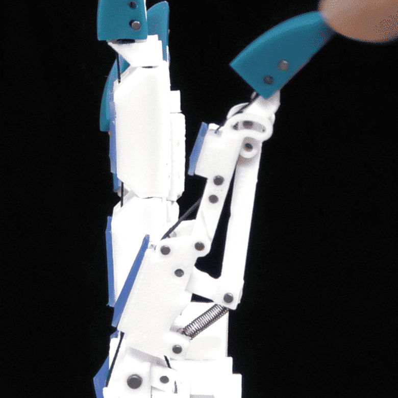
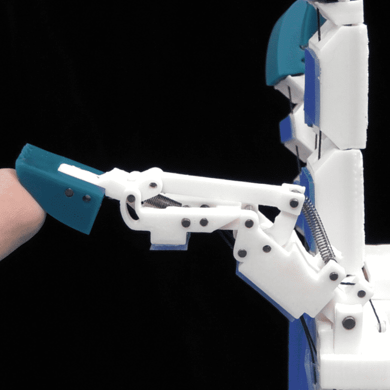
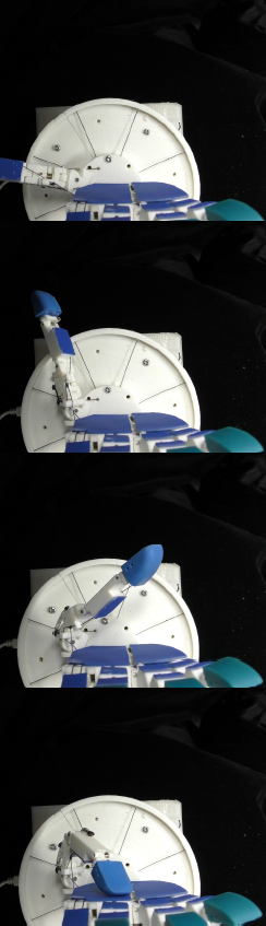
IV-C Main and special movements
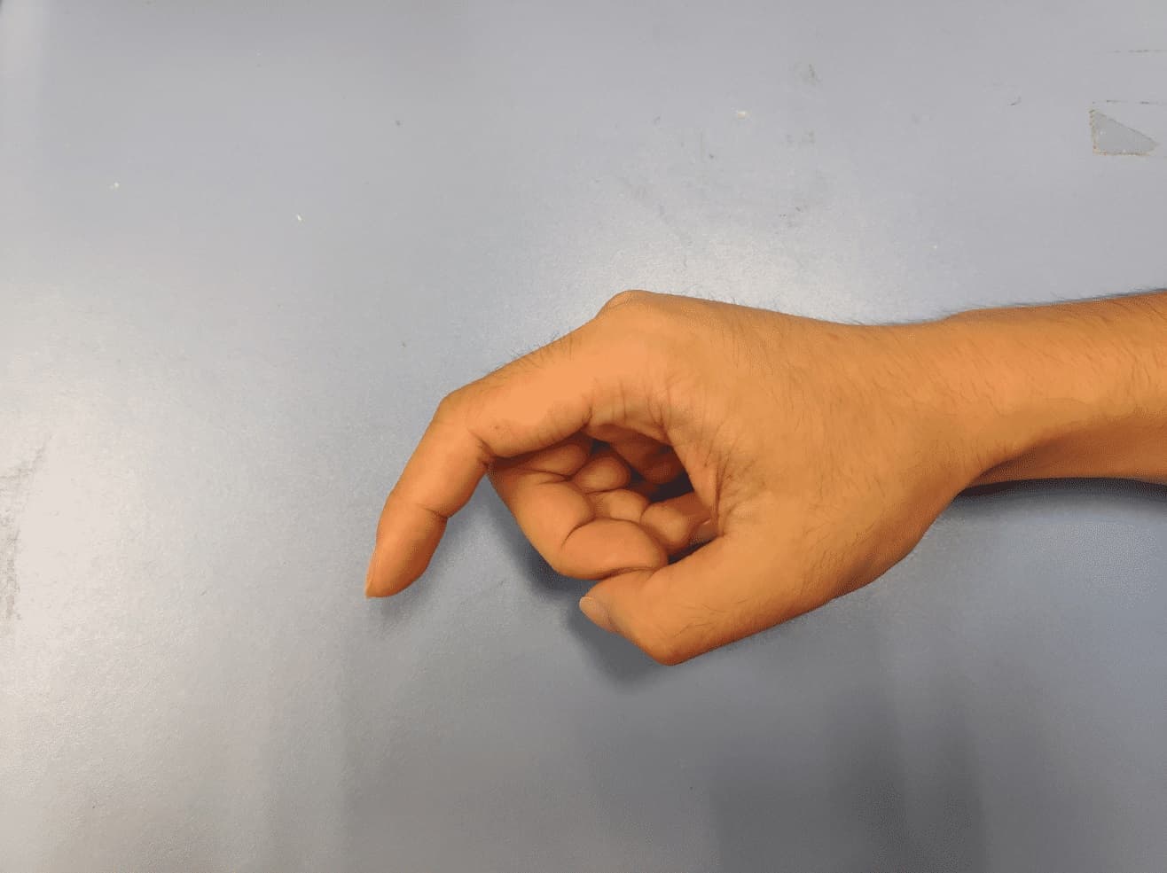
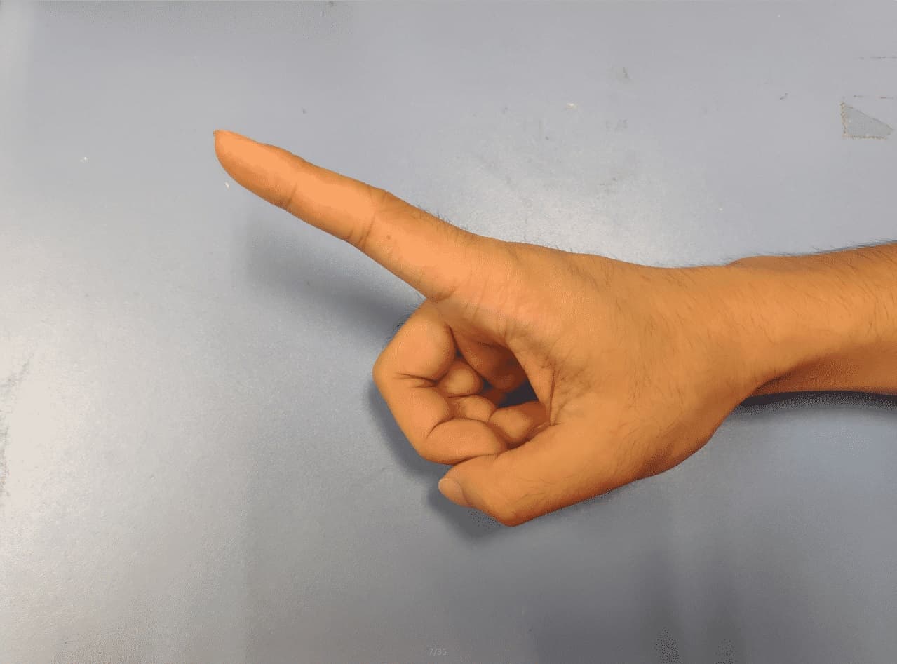
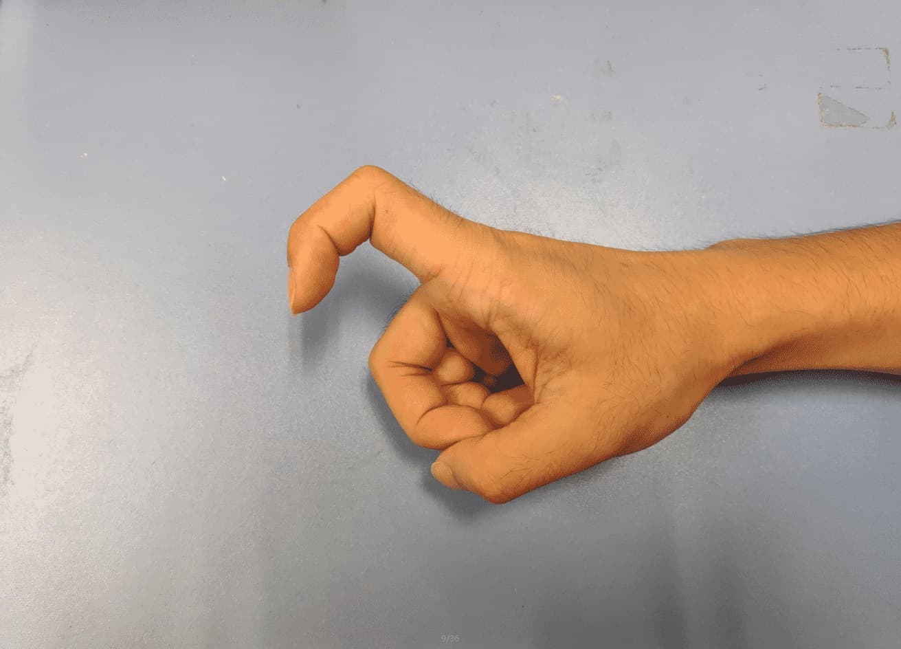
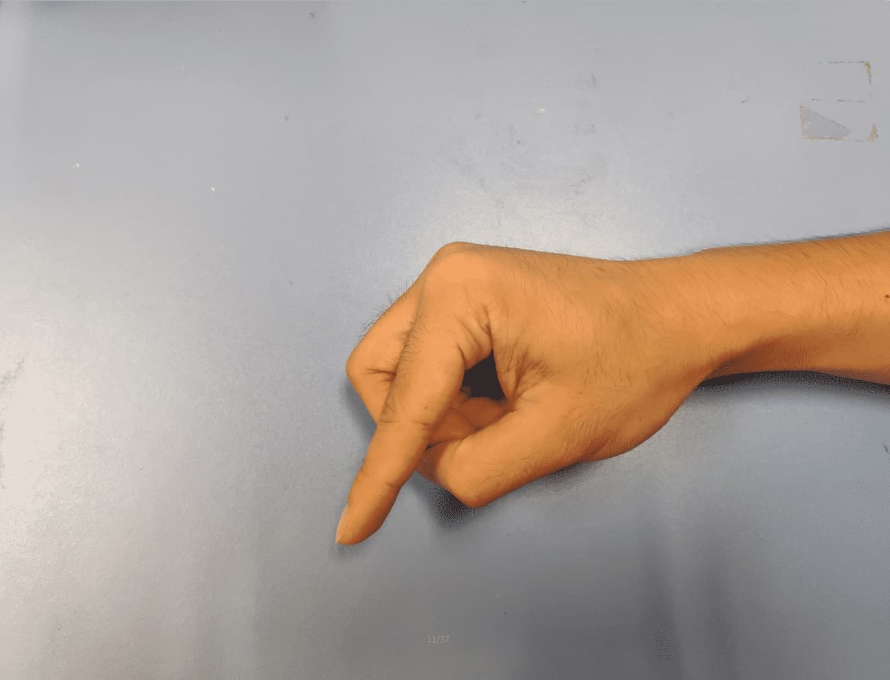
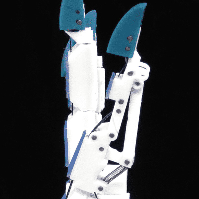
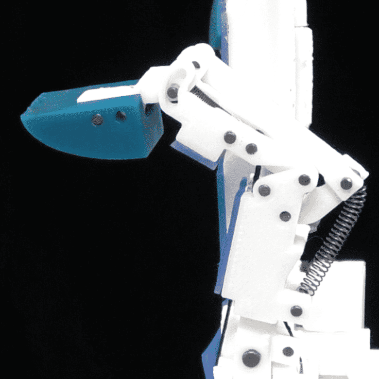
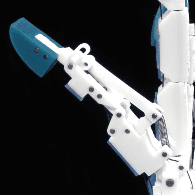
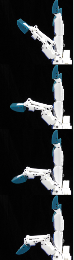
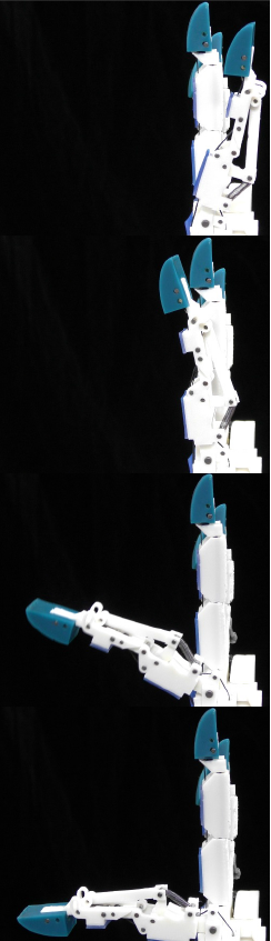
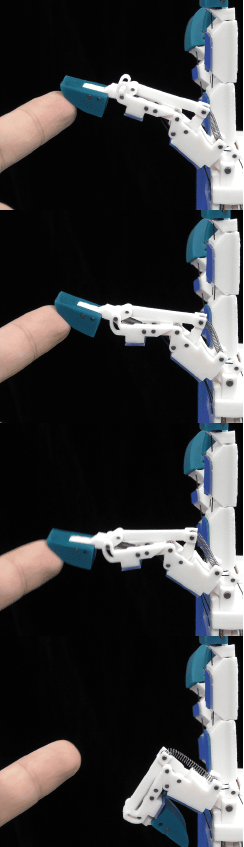
As shown in Figure 7(a), the thumb accomplishes the CMC joint’s adduction, abduction, flexion, as well as MCP joint’s pronation along with MCP joint’s flexion and IP joint’s flexion. In Figure 7(b) and Figure 7(c), our robotic hand achieves the independent movements of IP and MCP joints. In addition, as shown in Figure 7(d), our index finger’s fingertip can arrive at a compliant and adaptive posture under external forces and actively resist external forces by tightening the blue line which is illustrated in Figure 5(c).
IV-D Grasping experiments
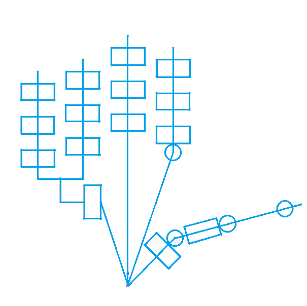
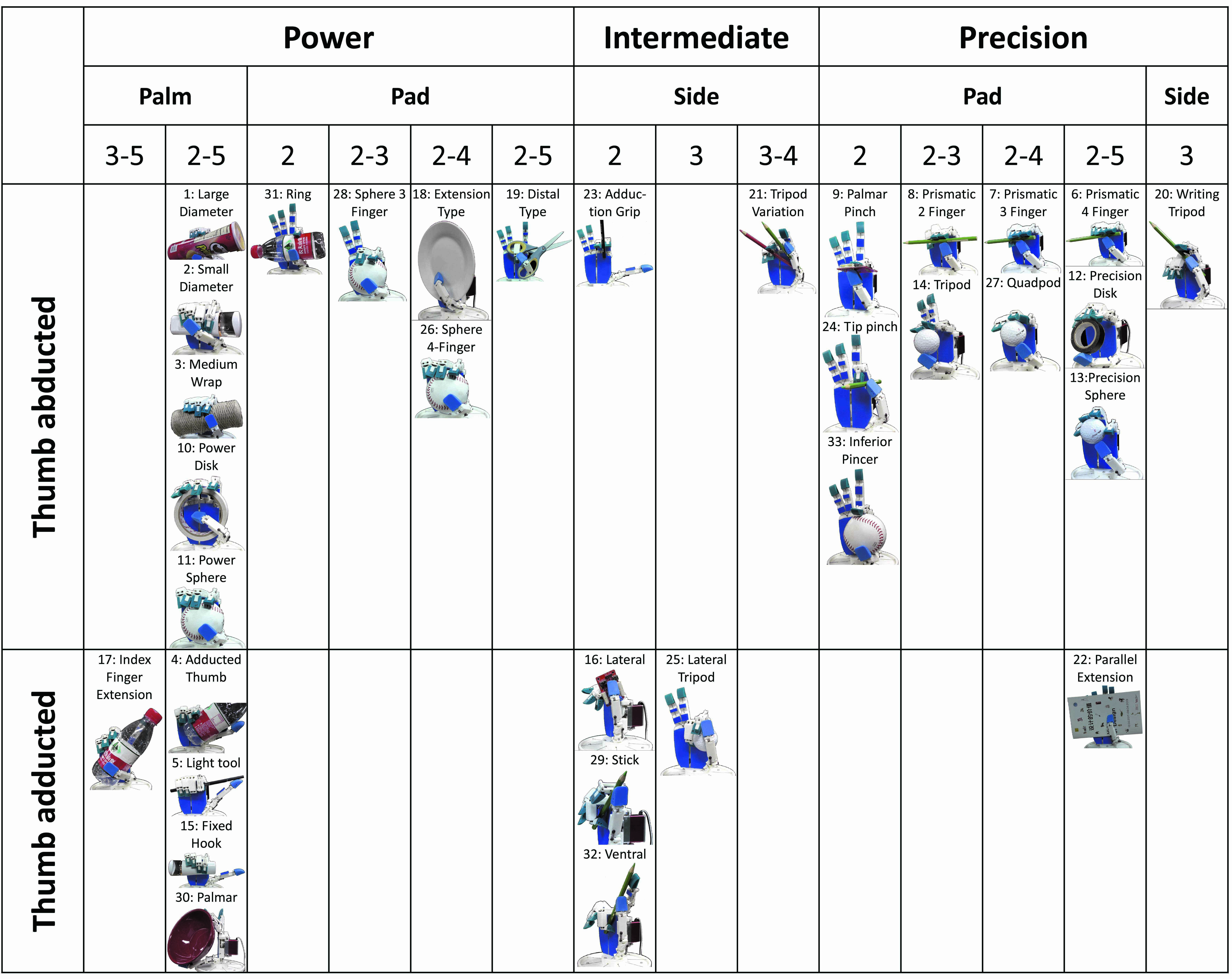
One of our contributions is that the proposed robotic hand is of great dexterity and can pass all challenging tests defined in the GRASP taxonomy [20], where a robotic hand need to accomplish 33 standard grasping postures in different tasks. As shown in Figure 8, our CATCH hand can successfully accomplish all the 33 static and stable grasping postures. For more details, please refer to the video.
V Conclusion and Future Works
In this work, we have designed an anthropomorphic robotic hand that closely mimics the control strategies of human hand’s index finger with a novel four-bar linkage to achieve independent control of IP and MCP joints. What’s more, we reconstruct muscles’ functions in the thumb and replace 9 human muscle tendons with 3 cables using task-oriented design to pass all challenging tests defined in the GRASP taxonomy [20]. However, because the cable-driven design cannot decouple joints’ movements, we need to calibrate the relationship between joint angles and corresponding cables’ lengths, which is troublesome and time-consuming and further prevents us from achieving precise and high-speed control like motor-driven anthropomorphic hand333UT/HDS Hand: https://www.youtube.com/watch?v=vu6APoC0IOA.
In future work, we are planning to change the phalanges and the palm’s design from 3D printing of hard materials to soft materials, in order to improve the hand’s compliance with contact objects and to increase the grasping capability in terms of accomplishing more general grasping tasks like grasping all the YCB objects [32].
References
- [1] T. Mouri, H. Kawasaki, K. Yoshikawa, J. Takai, and S. Ito, “Anthropomorphic robot hand: Gifu hand iii,” in Proc. Int. Conf. ICCAS, 2002, pp. 1288–1293.
- [2] R. Deimel and O. Brock, “A novel type of compliant and underactuated robotic hand for dexterous grasping,” The International Journal of Robotics Research, vol. 35, no. 1-3, pp. 161–185, 2016.
- [3] J. Zhou, S. Chen, and Z. Wang, “A soft-robotic gripper with enhanced object adaptation and grasping reliability,” IEEE Robotics and Automation Letters, vol. 2, no. 4, pp. 2287–2293, 2017.
- [4] J. Zhou, J. Yi, X. Chen, Z. Liu, and Z. Wang, “Bcl-13: A 13-dof soft robotic hand for dexterous grasping and in-hand manipulation,” IEEE Robotics and Automation Letters, vol. 3, no. 4, pp. 3379–3386, 2018.
- [5] S. Hand, “Shadow robot company,” 2013.
- [6] R. R. Ma, L. U. Odhner, and A. M. Dollar, “A modular, open-source 3d printed underactuated hand,” in Robotics and Automation (ICRA), 2013 IEEE International Conference on. IEEE, 2013, pp. 2737–2743.
- [7] T. Wiste and M. Goldfarb, “Design of a simplified compliant anthropomorphic robot hand,” in Robotics and Automation (ICRA), 2017 IEEE International Conference on. IEEE, 2017, pp. 3433–3438.
- [8] M. B. Bhadugale, “Anthropomorphically inspired design of a tendon-driven robotic prosthesis for hand impairments,” 2018.
- [9] A. D. Deshpande, Z. Xu, M. J. V. Weghe, B. H. Brown, J. Ko, L. Y. Chang, D. D. Wilkinson, S. M. Bidic, and Y. Matsuoka, “Mechanisms of the anatomically correct testbed hand,” IEEE/ASME Transactions on Mechatronics, vol. 18, no. 1, pp. 238–250, 2013.
- [10] D. D. Wilkinson, M. V. Weghe, and Y. Matsuoka, “An extensor mechanism for an anatomical robotic hand,” in IEEE International Conference on Robotics and Automation, vol. 1, 2003, pp. 238–243.
- [11] M. V. Weghe, M. Rogers, M. Weissert, and Y. Matsuoka, “The ACT hand: design of the skeletal structure,” in IEEE International Conference on Robotics and Automation, 2004, pp. 3375–3379.
- [12] L. Y. Chang and Y. Matsuoka, “A kinematic thumb model for the ACT hand,” in IEEE International Conference on Robotics and Automation, 2006, pp. 1000–1005.
- [13] A. D. Deshpande, R. Balasubramanian, R. Lin, B. Dellon, and Y. Matsuoka, “Understanding variable moment arms for the index finger MCP joints through the ACT hand,” in IEEE RAS EMBS International Conference on Biomedical Robotics and Biomechatronics, 2008, pp. 776–782.
- [14] A. D. Deshpande, R. Balasubramanian, J. Ko, and Y. Matsuoka, “Acquiring variable moment arms for index finger using a robotic testbed,” IEEE Transactions on Biomedical Engineering, vol. 57, no. 8, pp. 2034–2044, 2010.
- [15] T. D. Niehues and A. D. Deshpande, “Variable thumb moment arm modeling and thumb-tip force production of a human-like robotic hand,” Journal of biomechanical engineering, vol. 139, no. 10, p. 101005, 2017.
- [16] I. Kapanji, “the physiology of the joints: Upper limb,” London (UK): Churchill Livingstone, 1983.
- [17] Z. Xu and E. Todorov, “Design of a highly biomimetic anthropomorphic robotic hand towards artificial limb regeneration,” in IEEE International Conference on Robotics and Automation, 2016, pp. 3485–3492.
- [18] https://en.wikipedia.org/wiki/Dorsal˙interossei˙of˙the˙hand, 2018, [Online; accessed 31-August-2018].
- [19] Z. Xu, E. Todorov, B. Dellon, and Y. Matsuoka, “Design and analysis of an artificial finger joint for anthropomorphic robotic hands,” in Robotics and Automation (ICRA), 2011 IEEE International Conference on. IEEE, 2011, pp. 5096–5102.
- [20] T. Feix, J. Romero, H. Schmiedmayer, A. M. Dollar, and D. Kragic, “The grasp taxonomy of human grasp types,” IEEE Transactions on Human-Machine Systems, vol. 46, no. 1, pp. 66–77, 2016.
- [21] J. Landsmeer, “The anatomy of the dorsal aponeurosis of the human finger and its functional significance,” The Anatomical Record, vol. 104, no. 1, pp. 31–44, 1949.
- [22] https://en.wikipedia.org/wiki/Extensor˙indicis˙muscle, 2018, [Online; accessed 31-August-2018].
- [23] N. Palastanga, D. Field, and R. Soames, Anatomy and human movement: structure and function. Elsevier Health Sciences, 2006, vol. 20056.
- [24] T. A. Schreuders and H. J. Stam, “Strength measurements of the lumbrical muscles,” Journal of Hand Therapy, vol. 9, no. 4, pp. 303–305, 1996.
- [25] W. L. Buford Jr, S. Koh, C. R. Andersen, and S. F. Viegas, “Analysis of intrinsic–extrinsic muscle function through interactive 3-dimensional kinematic simulation and cadaver studies,” The Journal of hand surgery, vol. 30, no. 6, pp. 1267–1275, 2005.
- [26] K. Wang, E. P. McGlinn, and K. C. Chung, “A biomechanical and evolutionary perspective on the function of the lumbrical muscle,” The Journal of hand surgery, vol. 39, no. 1, pp. 149–155, 2014.
- [27] S. V. S. Jan, M. Rooze, J. Van Audekerke, and L. Vico, “The insertion of the extensor digitorum tendon on the proximal phalanx,” Journal of Hand Surgery, vol. 21, no. 1, pp. 69–76, 1996.
- [28] M. Baratz, C. Schmidt, and T. Hughes, “Extensor tendon injuries,” Green’s operative hand surgery, vol. 5, 2005.
- [29] T. G. Marshall, B. Sivakumar, B. J. Smith, and M. S. Hile, “Mechanics of metacarpophalangeal joint extension,” The Journal of hand surgery, 2018.
- [30] M. F. Bear, B. W. Connors, and M. A. Paradiso, Neuroscience. Lippincott Williams & Wilkins, 2007, vol. 2.
- [31] J. J. Crisco, E. Halilaj, D. C. Moore, T. Patel, A.-P. C. Weiss, and A. L. Ladd, “In vivo kinematics of the trapeziometacarpal joint during thumb extension-flexion and abduction-adduction,” The Journal of hand surgery, vol. 40, no. 2, pp. 289–296, 2015.
- [32] B. Calli, A. Singh, A. Walsman, S. Srinivasa, P. Abbeel, and A. M. Dollar, “The ycb object and model set: Towards common benchmarks for manipulation research,” in International Conference on Advanced Robotics, 2015, pp. 510–517.