Currently at ]Department of Electronic and Electrical Engineering, University of Sheffield, Mappin Street, Sheffield S1 3JD, United Kingdom.
Magnetoresistance in an electronic cavity coupled to one-dimensional systems
Abstract
In the present work we performed magnetoresistance measurement in a hybrid system consisting of an arc-shaped quantum point contact (QPC) and a flat, rectangular QPC, both of which together form an electronic cavity between them. The results highlight a transition between collimation-induced resistance dip to a magnetoresistance peak as the strength of coupling between the QPC and the electronic cavity was increased. The initial results show the promise of hybrid quantum system for future quantum technologies.
Recent development in quantum technologies has stimulated research activities in integrating different quantum components in order to realize complex functionalityHu et al. (2007); Majer et al. (2007). It is therefore of fundamental interest to investigate coupling between discrete quantum devices. Coupling between electronic cavity and other quantum devices, such as quantum point contactKatine et al. (1997); Duncan et al. (2001); Yan et al. (2017a, b); Steinacher et al. (2017) (QPC) and quantum dotRössler et al. (2015); Dias da Silva et al. (2017); Ferguson et al. (2017) (QD), has attracted considerable attention. A hybrid device consisting of a QPC and an electronic cavity, as an example, provides a unique platform to investigate electronic equivalent of optical phenomena. This may be understood from the fact that electrons in such a system transport ballistically and accumulate phase along the quasi-classical trajectories, which is a close analogue of an optical cavity. Previous studies based on QPC-cavity hybrid devices reported results based on classical trajectories of electronsKatine et al. (1997); Duncan et al. (2001); Hersch, Haggerty, and Heller (1999, 2000) as well as quantum effects manifested as conductance fluctuationsKatine et al. (1997); Duncan et al. (2001) and Ahronov-Bohm phase shift as a function of cavity sizeDuncan et al. (2001).
In the present work, we studied magnetoresistance in a hybrid system in a controlled manner with the assistance of two QPCs which form an electronic cavity between them. We show the strength of coupling between the QPC and cavity states can be monitored by oscillation in the magnitude of central peak/dip in magnetoresistance.
The devices studied in the work were fabricated from a high mobility two-dimensional electron gas (2DEG) formed at the interface of GaAs/Al0.33Ga0.67As heterostructure. The measured electron density (mobility) was 1.801011cm-2 (2.17106cm2V-1s-1) at 1.5 K, which ensured that both the calculated mean free path and phase coherence length Altshuler, Aronov, and Khmelnitsky (1982); Pooke et al. (1989) were over 10 m which were larger than electron propagation length. The experiments were performed in a cryofree dilution refrigerator with a lattice temperature of 20 mK using the standard lockin technique.
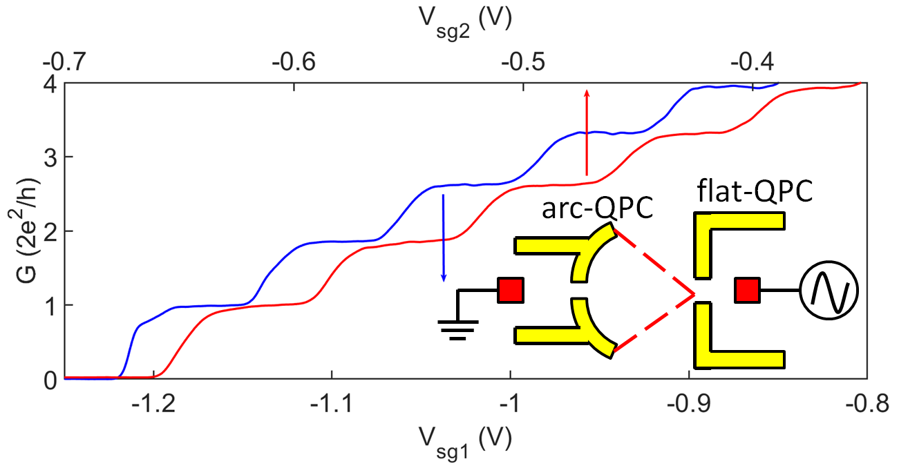
The hybrid device consists of a pair of arc-shaped gates with a QPC (referred as arc-QPC) forming in the center of arc-gates and another pair of rectangular QPC (named as flat-QPC) as depicted in Fig. 1. The QPCs are assembled in such a way that the geometrical center of the arc (shaped gates) aligns with the saddle point of the flat-QPC. An electronic cavity is formed when QPCs are activated by depleting the 2D electrons underneath the gatesYan et al. (2017a, b). Both the arc-QPC and flat-QPC showed well defined one-dimensional conductance quantization when they were characterised individually, Fig. 1.
In the presence of a small transverse magnetic field, the magnetoresistance of flat-QPC or arc-QPC exhibited a weak-localization peak similar to reported previouslyReulet, Bouchiat, and Mailly (1995); Koester et al. (1996). However, the non-trivial features started appearing when the hybrid device was formed, i.e. both flat-QPC and arc-QPC were activated.
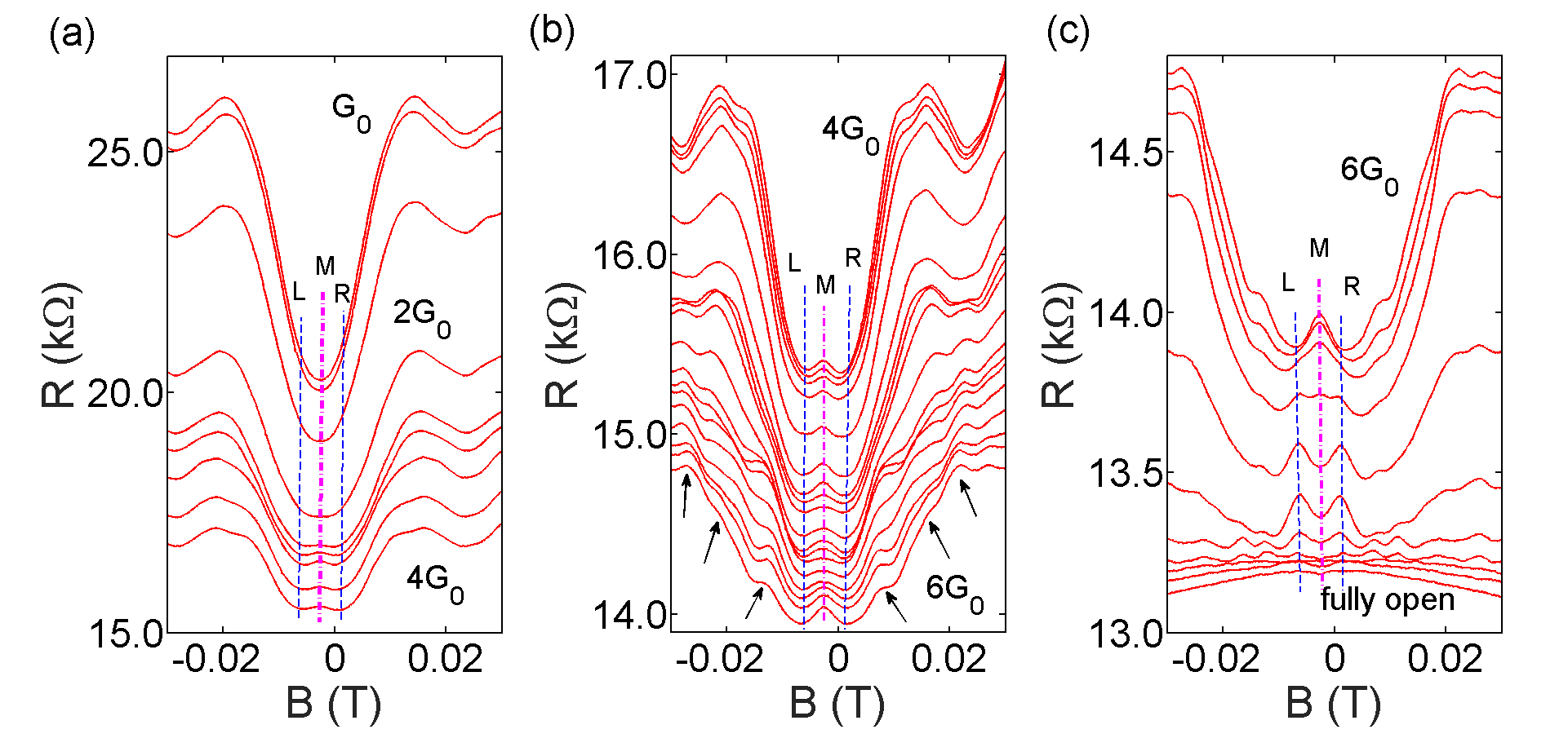
In the first experiment, the flat-QPC served as an emitter while the arc-QPC was used as a collector, see inset of Fig. 1. The voltage applied to the flat-QPC was incremented slowly corresponding to a conductance of G0 (G0=) up to 1D channel fully open while the arc-QPC was fixed at G0. The magnetoresistance was investigated in three different regimes according to flat-QPC conductance.
In regime 1, the flat-QPC was incremented from G0 to 4G0, Fig. 2(a). A dip in resistance (marked by the magenta dashed line) was observed around 0 T when the flat-QPC conductance G 2G0 which is due to the fact that the injected electrons had a relatively small angular spread owing to strong collimation in low conductance regimeMolenkamp et al. (1990); Heindrichs et al. (1998). The electrons tend to propagate from the flat-QPC through the arc-QPC directly without backscattering; however, the applied magnetic field guides the injected electrons to the arc-shaped boundary wall of the arc-QPC and thus results in backscattering, which in turn triggers a rise in resistance. In this respect, our hybrid system is similar to a long quantum wire where scattering at the boundary was suggested to introduce a central dip in magnetoresistanceThornton et al. (1989). An offset in central dip in magnetoresistance of 3 mT could be due to magnetic hysteresis of the superconducting magnet. On increasing G to 4G0, a central magnetoresistance peak started forming. The zero-field magnetoresistance peak in electronic billiards is a result of geometry induced closed loopBerry et al. (1994) (in other words, an analogue to weak localization). A large angular spread at higher G makes injected electrons to be reflected at the boundary wall of the arc-shaped QPCs, thus forming a close loop even at zero magnetic field; on the hand, a relatively small angular spread at low conductance makes such reflection unlikely to happen without the assistance of a magnetic field. The backscattered electrons will be refocused to the saddle point of flat-QPC.
In regime 2, Fig. 2(b), the flat-QPC was set from 4G0 to 6G0, the magnitude of the central peak fluctuated in the sense that the central peak gradually smeared out when the flat-QPC conductance was close to 5G0, and then reappeared on further increasing the conductance of flat-QPC. The fluctuation will be discussed in detail in Fig. 5. Meanwhile it was also noticed that multiple weak-satellite peaks, marked by black arrows in Fig. 2(b), occurred in this regime. It was suggestedDuncan et al. (2001) in a previous work that the appearance of these satellite peaks was an indication of Aharonov-Bohm effect and each peak was associated with a particular classical orbit. We suggest that although the satellite peaks might be relevant with classical orbits, however, Aharonov-Bohm effect did not occur in our experiment considering the fact that the satellites peaks were almost absent in regime 1 or regime 3.
In regime 3 (6G0 to fully open emitter), Fig. 2(c), the central peak gradually splits into two peaks around the 1D-2D transition regime of the flat-QPC and eventually all the features smeared out and only a smooth background was observed with the flat-QPC entering into the 2D regime. The smooth background agrees well the weak-localization signal when the arc-QPC was characterised individually.
To be noted that Shubnikov-de Haas oscillation started appearing in all the three regimes when the magnetic field exceeded 0.13 T (data is not shown).
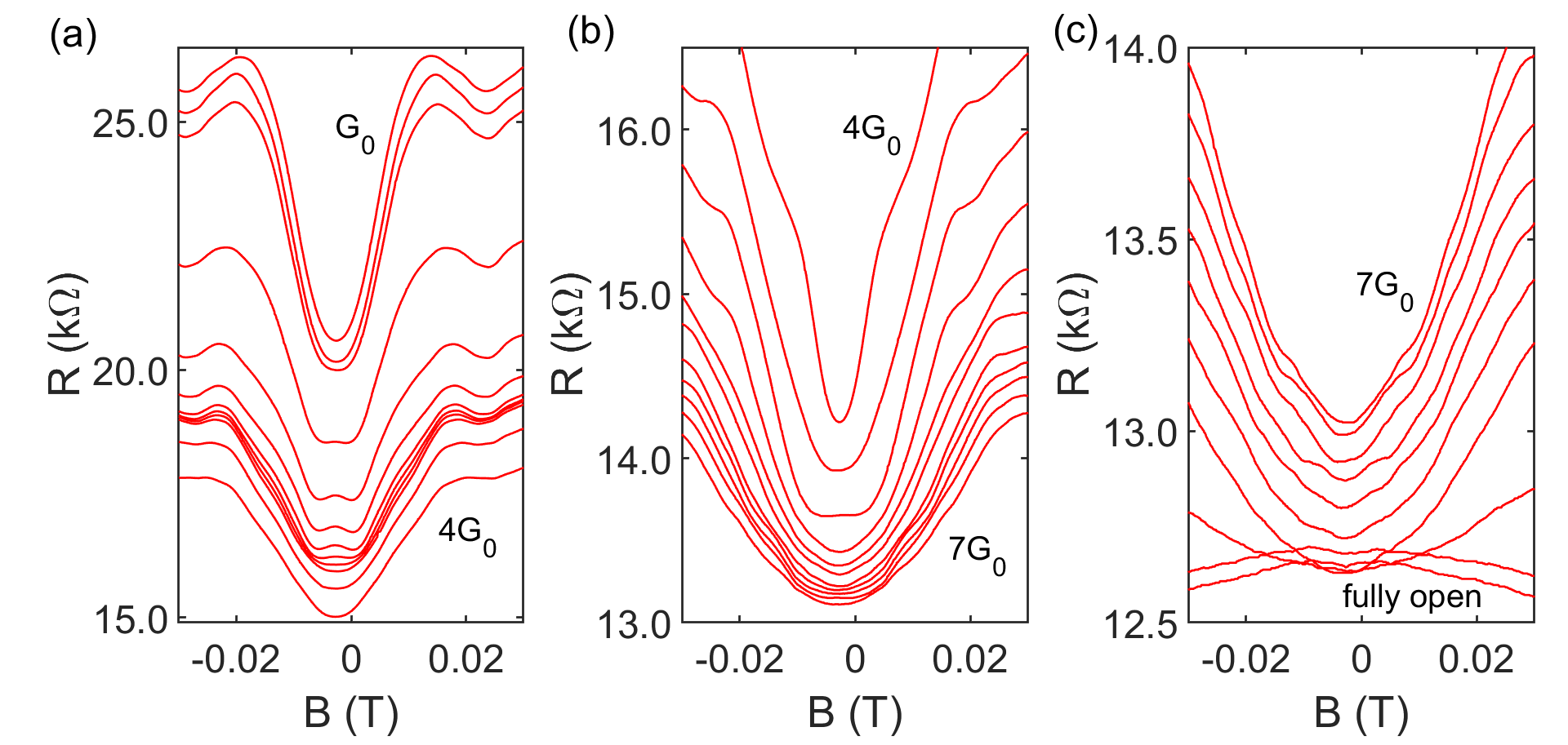
To ensure the observation did not simply arise from the superposition of the magneto-spectrum of two individual QPCs, we reversed the role of emitter and collector. In setup II the arc-QPC was utilized as an emitter and incremented while the flat-QPC functioned as a collector and was fixed at G0. In addition, the ac signal is fed to the left Ohmic [Fig. 1(a)] whereas the right Ohmic is grounded in setup II.The results are summarized in Fig. 3. Results in regime 1, Fig. 3(a), was similar to that observed with setup I. However, the central dip dominated in regime 2 [Fig. 3(b)] and 3 [Fig. 3(c)] which was considerably different from its counterpart in Fig. 2 where more features were resolved. The behaviour in setup II was similar to the magnetoresistance in two regular QPC in seriesHeindrichs et al. (1998). It is interesting to mention that satellite peaks observed in Fig. 2(b) did not occur in setup II. A comparison between setup I and II also suggests that the complicated evolution of magnetoresistance observed in Fig. 2 did not directly arise from the form of wavefunction at different emitter conductance; otherwise, setup II should exhibit similar behaviour.
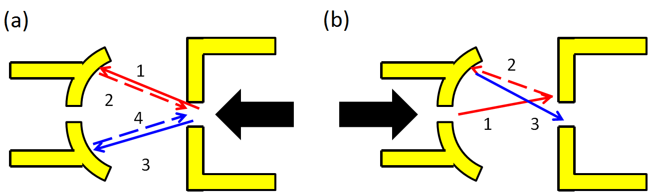
The difference between the results from two setup could be understood with a semi-classical picture as shown in Fig. 4. Electrons injected from the flat-QPC, which aligns with the geometrical centre of the arc (i.e. arc-QPC), experience an arc-shaped reflector which traps the electrons in an electronic cavity defined by these QPCs. The injected electrons after reflection at the boundary wall of the arc would be directed towards the flat-QPC. Owing to the geometry of cavity defined between the arc- and flat-QPCs, electrons would be trapped in a closed loop such as events 14 as shown in Fig. 4(a) until the total propagation length exceeded the mean free path; phase associated with such a close loop is unlikely to be averaged out, therefore corrections to the resistance, i.e. the central magnetoresistance peak, due to the accumulated phase was observable. On the other hand, the trajectory of electrons injected from the arc-QPC, i.e. setup II, did not necessarily form a closed loop, so that it was relatively easy for the injected electrons to get through the hybrid system via a series of scattering events, for instance events 13 as depicted in Fig. 4(b). Electron trajectory in the second scenario is more arbitrary and the trajectory-determined phase tends to be averaged out, which leads to no obvious corrections in the resistance.
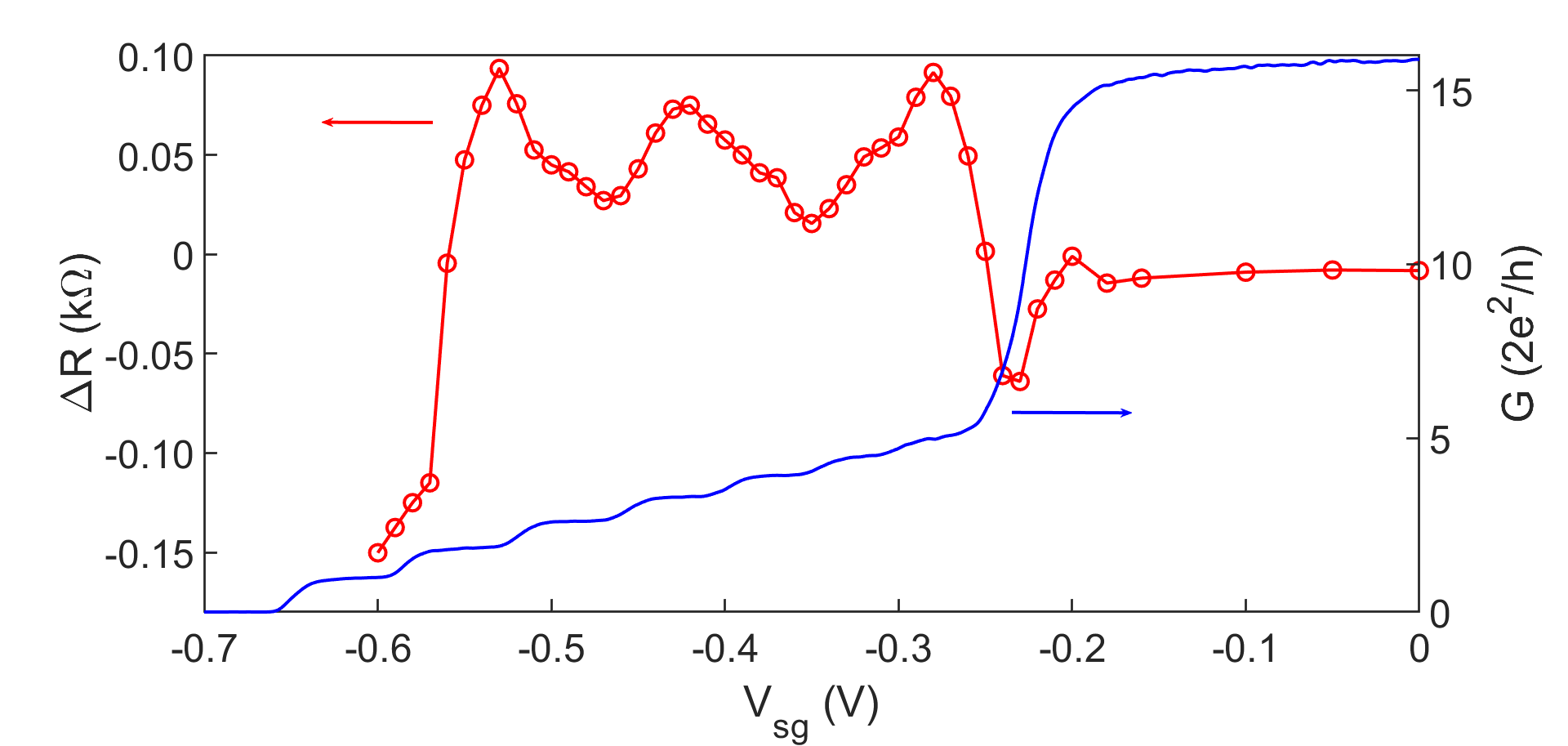
After addressing the difference between the two setup, we discuss a possible mechanism behind the observed fluctuation of the central features with flat-QPC serving as an emitter. To quantify the fluctuation, we defined the strength of the central feature (could be dip or peak) as such R = RM-(RL+RR)/2, where RM, RL and RR refer to the resistance measured at given magnetic field marked in Fig. 2 (although in dip dominant regime there was not noticeble feature at or , we still use the resistance at the same field for systematic investigation). It was seen that R followed a quasi-periodic oscillationSaito et al. (1994); Yan et al. (2017a, b); Katine et al. (1997); Duncan et al. (2001) when the flat-QPC was tuned into the 1D regime (Vsg -0.25 V); the fluctuation smeared out when the flat-QPC entered the 2D regime as shown in Fig. 5. The fact that the peak of oscillation does not necessarily occur at each conductance plateau suggesting that it is not simply associated with occupation of 1D subband or electron collimation, which would otherwise produce peaks corresponding to each conductance plateau. Instead, the oscillation was an indication of the coupling between the cavity and QPC sates. Each peak in Fig. 5 is a result of removing a cavity mode, therefore peaks in R should occur when the change in radius of cavity matched a condition Katine et al. (1997), = N/2, where N is an integer and is the Fermi wavelength.
In conclusion we have shown magnetoresistance in a hybrid system consisting of QPCs coupled via an electronic cavity. It was found that the central magneto-feature around 0 T underwent a transition from dip into peak when the cavity was present whereas resistance dip dominated when the cavity was effectively absent. An oscillation of the strength of the central magneto-feature was observed as a consequence of coupling between the QPC and cavity sates. The results provide insight of coupling between discrete quantum devices which is valuable for further development of integrated quantum systems.
The work is funded by the Engineering and Physical Sciences Research Council (EPSRC), United Kingdom.
References
- Hu et al. (2007) Y. Hu, H. O. Churchill, D. J. Reilly, J. Xiang, C. M. Lieber, and C. M. Marcus, “A Ge/Si heterostructure nanowire-based double quantum dot with integrated charge sensor,” Nature nanotechnology 2, 622–625 (2007).
- Majer et al. (2007) J. Majer, J. Chow, J. Gambetta, J. Koch, B. Johnson, J. Schreier, L. Frunzio, D. Schuster, A. Houck, A. Wallraff, et al., “Coupling superconducting qubits via a cavity bus.” Nature 449, 443–447 (2007).
- Katine et al. (1997) J. A. Katine, M. A. Eriksson, A. S. Adourian, R. M. Westervelt, J. D. Edwards, A. Lupu-Sax, E. J. Heller, K. L. Campman, and A. C. Gossard, “Point contact conductance of an open resonator,” Phys. Rev. Lett. 79, 4806–4809 (1997).
- Duncan et al. (2001) D. S. Duncan, M. A. Topinka, R. M. Westervelt, K. D. Maranowski, and A. C. Gossard, “Aharonov-bohm phase shift in an open electron resonator,” Phys. Rev. B 64, 033310 (2001).
- Yan et al. (2017a) C. Yan, S. Kumar, M. Pepper, P. See, I. Farrer, D. Ritchie, J. Griffiths, and G. Jones, “Fano resonance in a cavity-reflector hybrid system,” Phys. Rev. B 95, 041407 (2017a).
- Yan et al. (2017b) C. Yan, S. Kumar, M. Pepper, P. See, I. Farrer, D. Ritchie, J. Griffiths, and G. Jones, “Interference effects in a tunable quantum point contact integrated with an electronic cavity,” Phys. Rev. Applied 8, 024009 (2017b).
- Steinacher et al. (2017) R. Steinacher, C. Pöltl, T. Krähenmann, A. Hofmann, C. Reichl, W. Zwerger, W. Wegscheider, R. Jalabert, K. Ensslin, D. Weinmann, et al., “Scanning gate experiments: from strongly to weakly invasive probes,” arXiv preprint arXiv:1709.08559 (2017).
- Rössler et al. (2015) C. Rössler, D. Oehri, O. Zilberberg, G. Blatter, M. Karalic, J. Pijnenburg, A. Hofmann, T. Ihn, K. Ensslin, C. Reichl, and W. Wegscheider, “Transport spectroscopy of a spin-coherent dot-cavity system,” Phys. Rev. Lett. 115, 166603 (2015).
- Dias da Silva et al. (2017) L. G. G. V. Dias da Silva, C. H. Lewenkopf, E. Vernek, G. J. Ferreira, and S. E. Ulloa, “Conductance and kondo interference beyond proportional coupling,” Phys. Rev. Lett. 119, 116801 (2017).
- Ferguson et al. (2017) M. S. Ferguson, D. Oehri, C. Rössler, T. Ihn, K. Ensslin, G. Blatter, and O. Zilberberg, “Long-range spin coherence in a strongly coupled all-electronic dot-cavity system,” Phys. Rev. B 96, 235431 (2017).
- Hersch, Haggerty, and Heller (1999) J. S. Hersch, M. R. Haggerty, and E. J. Heller, “Diffractive orbits in an open microwave billiard,” Phys. Rev. Lett. 83, 5342–5345 (1999).
- Hersch, Haggerty, and Heller (2000) J. S. Hersch, M. R. Haggerty, and E. J. Heller, “Influence of diffraction on the spectrum and wave functions of an open system,” Phys. Rev. E 62, 4873–4888 (2000).
- Altshuler, Aronov, and Khmelnitsky (1982) B. L. Altshuler, A. Aronov, and D. Khmelnitsky, “Effects of electron-electron collisions with small energy transfers on quantum localisation,” Journal of Physics C: Solid State Physics 15, 7367 (1982).
- Pooke et al. (1989) D. M. Pooke, N. Paquin, M. Pepper, and A. Gundlach, “Electron-electron scattering in narrow Si accumulation layers,” Journal of Physics: Condensed Matter 1, 3289 (1989).
- Reulet, Bouchiat, and Mailly (1995) B. Reulet, H. Bouchiat, and D. Mailly, “Magnetoconductance, weak localization and electron-electron interactions in semi-ballistic quantum wires,” EPL (Europhysics Letters) 31, 305 (1995).
- Koester et al. (1996) S. J. Koester, K. Ismail, K. Y. Lee, and J. O. Chu, “Weak localization in back-gated Si/ quantum-well wires fabricated by reactive ion etching,” Phys. Rev. B 54, 10604–10608 (1996).
- Molenkamp et al. (1990) L. W. Molenkamp, A. A. M. Staring, C. W. J. Beenakker, R. Eppenga, C. E. Timmering, J. G. Williamson, C. J. P. M. Harmans, and C. T. Foxon, “Electron-beam collimation with a quantum point contact,” Phys. Rev. B 41, 1274–1277 (1990).
- Heindrichs et al. (1998) A. S. D. Heindrichs, H. Buhmann, S. F. Godijn, and L. W. Molenkamp, “Classical rebound trajectories in nonlocal ballistic electron transport,” Phys. Rev. B 57, 3961–3965 (1998).
- Thornton et al. (1989) T. J. Thornton, M. L. Roukes, A. Scherer, and B. P. Van de Gaag, “Boundary scattering in quantum wires,” Phys. Rev. Lett. 63, 2128–2131 (1989).
- Berry et al. (1994) M. Berry, J. Katine, C. Marcus, R. Westervelt, and A. Gossard, “Weak localization and conductance fluctuations in a chaotic quantum dot,” Surface science 305, 495–500 (1994).
- Saito et al. (1994) M. Saito, T. Usuki, M. Okada, T. Futatsugi, R. Kiehl, and N. Yokoyama, “Coupling between one-dimensional states in a quantum point contact and an electron waveguide,” Applied physics letters 65, 3087–3089 (1994).