Optimizing the spectro-temporal properties of photon pairs from Bragg-reflection waveguides
Abstract
Bragg-reflection waveguides (BRWs) fabricated from AlGaAs provide an interesting non-linear optical platform for photon-pair generation via parametric down-conversion (PDC). In contrast to many conventional PDC sources, BRWs are made of high refractive index materials and their characteristics are very sensitive to the underlying layer structure. First, we show that the design parameters like the phasematching wavelength and the group refractive indices of the interacting modes can be reliably controlled even in the presence of fabrication tolerances. We then investigate, how these characteristics can be taken advantage of when designing quantum photonic applications with BRWs. We especially concentrate on achieving a small differential group delay between the generated photons of a pair and then explore the performance of our design when realizing a Hong-Ou-Mandel interference experiment or generating spectrally multi-band polarization entangled states. Our results show that the versatility provided by engineering the dispersion in BRWs is important for employing them in different quantum optics tasks.
1 Introduction
Parametric down-conversion (PDC) offers means for comparably simple generation of non-classical light that can be used as a robust information carrier in a variety of quantum optics applications [1, 2]. Nevertheless, the spectral properties of the PDC emission, which largely stem from the material dispersion, play a crucial role in deciding for which applications a photon-pair source is suitable [3, 4, 5, 6, 7]. The intrinsic spectral characteristics of PDC can even exclude the source from being directly applicable in a desired task, and therefore, spectral filtering is often employed to counter this drawback [8, 9, 10]. Otherwise, sophisticated shaping of the spectral extent of the PDC photons based on modulation or non-linear effects can be employed [11, 12, 13, 14]. Still, the most direct and efficient approach is the modification of the source’s intrinsic properties. This is also the case for state engineering in semiconductor Bragg-reflection waveguides (BRWs)[15, 16, 17, 18, 19].
BRWs are usually made of AlGaAs, which is an excellent integrated optics platform and possesses a large second-order optical nonlinearity. The photon pairs—signal and idler—emitted by PDC in BRWs, which need to fulfill energy and momentum conservation, can be engineered to be counter- [20] or co-propagating [21, 22]. We are interested in the latter case, in which both the fundamental and higher order spatial modes propagating in the structure are utilized [23, 24]. However, adapting BRW sources to specific quantum optics tasks requires suitable joint spectral properties of signal and idler. For this purpose, one can benefit from the lack of birefringence in the underlying semiconductor platform. In addition, the strong dispersion of these high refractive index materials [25] can be taken advantage of. Luckily, accurate experimental methods exist for the verification of the group refractive indices and their dispersion in these multimode waveguides [26, 27, 28].
In this paper, we perform a detailed simulation of the optical properties of the PDC emission from the BRW sample designed in Ref. [29]. We investigate its performance in specific quantum optics applications that rely on spectral and temporal indistinguishability of the PDC photons. We start in Section 2 by exploring the robustness of our design with respect to variations in its structure. In Section 3, we explore, how to minimize the average differential group delay between signal and idler. In Section 4, we show that the PDC emission from our BRW design produces a large spectral overlap between the photon pairs. Thereafter, in Section 5 we study the performance of our PDC source in two quantum optics tasks. We show that due to the optimized spectral and temporal overlap of signal and idler, our design can be used as a versatile source in Hong-Ou-Mandel (HOM) interference experiments and that it is well suited for the generation of spectrally multi-band polarization entanglement.
2 Effect of variations in the BRW layer parameters on the phasematching wavelength
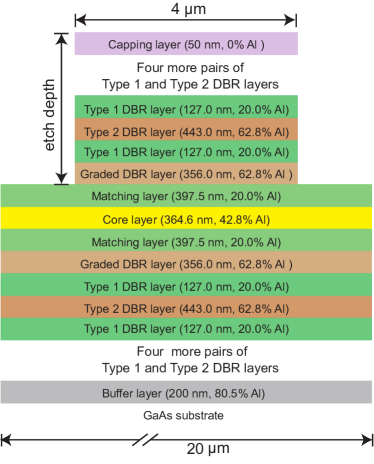
First, we investigate the effect of certain geometric and material parameters on the operating wavelength of our sample. We regard the graded BRW design from Ref. [29], which was optimized for simpler fabrication while maintaining a high efficiency for the desired PDC process. Figure 1 shows the cross-section and main parameters of the structure. This ridge waveguide consists of a core layer (CL) and two matching layers (ML) around the core, which are surrounded by six pairs of distributed Bragg reflectors (DBRs). The phasematching condition is fulfilled by guiding the pump light in the so-called Bragg mode, which is a higher-order spatial mode, whereas the PDC photon pairs are generated in total internal reflection modes. The phasematching is defined by the dispersion of the modes and is heavily affected by the material composition and geometric layout of the ridge. Therefore, it is very sensitive to the structural parameters, i.e. the layer thicknesses and their aluminum contents as well as the width and height of the ridge. Such deviations may arise for example due to imperfections in the fabrication process.
We employ a commercial mode solver [30] to determine the dispersion of the eigenmodes. The nominal design, which is depicted in Figure 1, has a ridge width of and a height of approximately denoted here as the etch depth. We use the model of Gehrsitz et al. in Ref. [25] to estimate the refractive indices of the individual layers, which are greatly dependent on their aluminum concentrations. The graded BRW supports a type-II PDC process such that signal and idler are cross-polarized. After solving the dispersion of the interacting modes, the phasematched wavelength triplets are found by searching for solutions of with , in which () describe the effective refractive indices of the signal (), idler () and pump () modes in terms of the wavelength . At the degeneracy , which we call the phasematching wavelength. For the graded BRW as shown in Figure 1 we find a phasematching wavelength of .
| Parameter | (i) | (ii) |
|---|---|---|
| ML thickness | ||
| ML Al content | ||
| CL thickness | ||
| CL Al content | ||
| Type 1 DBR thickness | ||
| Type 1 DBR Al content | ||
| Type 2 DBR thickness | ||
| Type 2 DBR Al content |
We then vary each layer parameter listed in Table 1 from its specified value by , while keeping the others fixed, and calculate the change in the phasematching wavelength of the graded BRW shown as case (i). It is apparent, that an increment in the layer thicknesses also increases the phasematching wavelength, while when regarding the aluminum contents the opposite is observed. This effectively means that one can simply scale the structure to achieve another phasematching wavelength without having to re-engineer the epitaxial structure. Moreover, we remark that these sensitivities have to be considered in the context of the practically achievable fabrication accuracies. We expect thickness accuracies better than and aluminum content accuracies of in absolute percentage points. As case (ii) in Table 1 we show the variation in the phasematching wavelength for the design in Figure 1 caused by the fabrication tolerance in the listed layer parameter, while the others are kept constant.
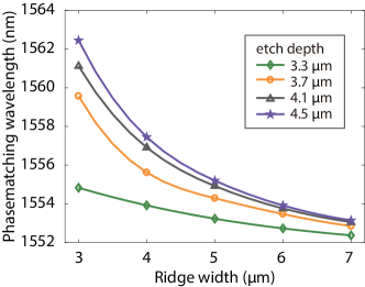
The ridge width [31, 32] and etch depth allow some posterior changes of the phasematching wavelength. After the epitaxial growth of the layers, their thickness can be determined and the ridge width and height can be adjusted accordingly. We show this effect in Figure 2, which illustrates the phasematching wavelength in terms of a typical range of ridge widths for different etch depths. The deeper etches cause the phasematching wavelength to depend stronger on the ridge width. Additionally, one can clearly see the increased effect of the stronger horizontal confinement of the modes for very narrow waveguides. Thus, the tuning range provided by employing different ridge widths greatly depends on the used etch depth.
3 Temporal overlap of signal and idler
While the effective refractive indices of signal, idler and pump determine the exact phasematching wavelength, the effective group refractive indices of these modes play a crucial role when regarding the spectro-temporal properties of the created photon pairs. For example, if signal and idler group velocities differ from each other, their wavepackets walk temporally off during the propagation in the BRW, which results in temporal distinguishability. Some applications such as the generation of polarization entanglement, which we investigate in more detail in Section 5, are very sensitive to this average differential group delay (DGD). Only if it is negligible, such a scheme can be implemented without external optical delay compensation [19, 33]. The average DGD between the signal and idler wavepackets is given by
| (1) |
where is the length of the waveguide, and ( and ) indicate the group velocities (group refractive indices) of signal and idler, respectively, and is the speed of light in vacuum. The group refractive index of each mode is defined as
| (2) |
in terms of its effective refractive index and angular frequency .
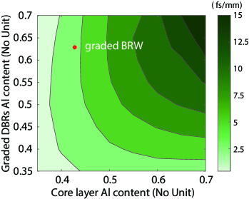
One usually resorts to numerical simulations in order to accurately predict the BRW properties since an analytical solution yielding the effective refractive indices of BRW modes is only approximately possible for much simpler structures than the ones regarded here. In our graded BRW, the spatial modes of signal and idler mostly propagate in the matching layers and are confined by the surrounding core and graded DBR layers. Following West and Helmy [23], who showed that the aluminum content of the surrounding layers affect the dispersion of the total-internal reflection and Bragg modes most strongly, we investigate the effect of these layers on the dispersion between signal and idler. As shown in Figure 3, we simulate the average DGD per length in our graded BRW as a function of the aluminum content of the core and graded DBR layers, while keeping the other parameters unchanged. We find that a decrease of the aluminum content in the layers surrounding the matching layer leads to a lower average DGD.
| Structure | ||||
|---|---|---|---|---|
| graded BRW (Figure 1) | 3.3633 | 3.3607 | 0.0026 | 4.3921 |
| M-core BRW (Figure 4) | 3.3385 | 3.3292 | 0.0093 | 4.0363 |
| Ref. [34] | 3.33 | 3.32 | 0.01 | 4.05 |
| Ref. [27] | 3.31(2) | 0.007(2) | 3.72(3) | |
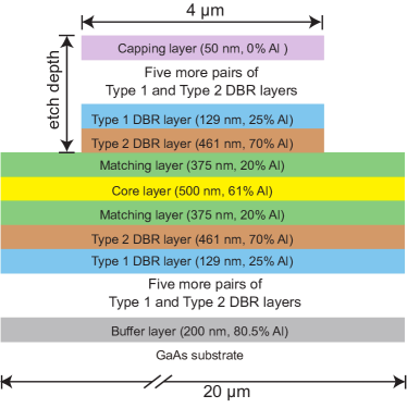
Next, we compare the average DGD in the graded BRW with the one in a typical structure, the multilayer core (M-core) structure shown in Figure 4, employed by us and others in the past [35, 22, 34, 27]. First, by comparing the aluminum contents of the graded and M-core BRWs it is easy to judge that the graded BRW has a smaller average DGD than the M-core BRW, because the aluminum concentration contrast between core and matching layers is smaller. Second, we perform a complete simulation of the dispersion of the different modes in these two structures with commercial solvers and present in Table 2 the group refractive indices of the relevant modes. In the graded BRW the group index difference between signal and idler is only , which corresponds to a small remaining average DGD of only , whereas that in the M-core BRW is 3.6 times larger.
4 Spectral overlap of signal and idler
The effective group refractive indices of signal and idler not only cause a temporal delay between their wavepackets, but also considerably influence their joint spectral properties. Since the signal and idler beams from our BRWs are cross-polarized, their group refractive indices slightly differ from each other as presented in Table 2. In our case this leads to spectral distinguishability between signal and idler, since their allowed frequency ranges differ from each other. Next, we study its effect.
The photon-pair state generated in the PDC process is given as [36]
| (3) |
where is the joint spectral amplitude (JSA) expressed in terms of the signal and idler angular frequencies, respectively, and is the photon creation operator generating photons either in horizontal (H) or vertical (V) polarization. With the help of the constant factor the JSA is normalized to . Due to energy conservation, is maintained in the PDC process with denoting the angular frequency of pump.
Following Refs [34, 27] we write the JSA as a product of the pump beam spectral envelope , in which is related to the pump bandwidth and denotes its central angular frequency, and the phasematching function , in which accounts for the phase mismatch. We describe it in terms of the propagation constants () of pump, signal, and idler. Moreover, we investigate the JSA around a phasematched frequency triplet , for which . Thus, we re-write the phase mismatch in terms of the detunings , and approximate it as
in which and are related to the effective group refractive indices of the interacting modes.
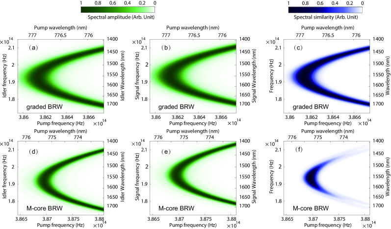
In Table 3 we list the phasematching parameters for the two investigated BRW designs. With these parameters we simulate the photon-pair characteristics assuming a Gaussian pump amplitude with a full width at half maximum (FWHM) of and a waveguide length of . We keep these parameters the same in all the following simulations. For the graded BRW structure we illustrate in Figure 5 (a-b) the single photon spectra of signal and idler, respectively, as well as in Figure 5 (c) their product for a better visualization of the similarity of their spectral extent. In Figure 5 (d-f) we present the same for the M-core BRW structure. Since the spectral extent of signal and idler depends strongly on the group refractive indices of the interacting modes, a comparison between Figure 5(c) and (f) clearly reveals the differences in the optical properties of PDC photons emitted from the two investigated BRW structures.
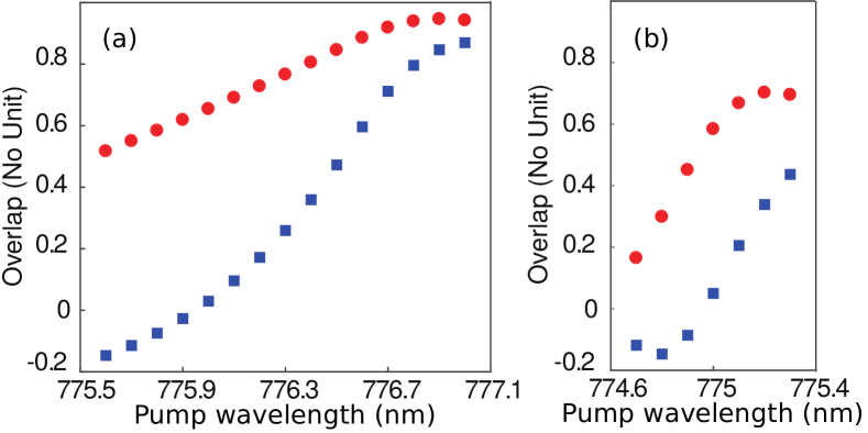
In order to investigate the spectro-temporal indistinguishability of signal and idler, we calculate their overlap given by [37, 38]
| (4) |
in terms of a temporal delay , which can be introduced by retarding the signal and idler wavepackets relative to each other. The overlap measures the symmetry of the JSA with respect to the exchange of signal and idler frequencies and includes also a temporal compensation. In Figure 6(a) we present the overlap values for the graded BRW structure and in Figure 6(b) for the M-core BRW structure with respect to the central wavelength of the pump beam. The overlap reaches a value as high as 85% (44%) for the graded (M-core) BRW structure without any temporal compensation. If the optimal temporal compensation of approximately () is applied, the value of the overlap increases to its maximal value of 94.6% (69.5%). When detuning the pump towards shorter wavelengths, the overlap gradually decreases for both investigated BRWs. However, the decay is faster in the M-core BRW structure due to the worse spectral similarity. The overlap value can even become negative if the temporal delay between signal and idler is not compensated. This effect can be taken advantage of when investigating the bunching of photon pairs next in Section 5.
5 BRWs in quantum optics applications
The spectro-temporal properties of photon pairs play a crucial role when adapting a PDC source to a quantum optics task. Therefore, we compare the performance of both investigated BRW structures in such applications. We start by exploring their suitability for a HOM quantum interference experiment [39, 40, 41] and thereafter study the preparation of spectrally multi-band polarization entanglement [17, 18, 33].
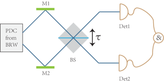
In the HOM interference experiment [3] as sketched in Figure 7 the probability of measuring a coincidence click between the output ports of a symmetric beam splitter, when sending a photon pair from PDC to its input ports, is directly connected to the overlap in Equation 4 and is given by [37]
| (5) |
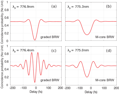
assuming that our BRW emits PDC with only a small amount of spurious noise such that the background from higher-photon number contributions can be neglected [42]. We simulate the HOM interference for the two investigated BRW structures at their respective degeneracy wavelengths and far away from them. In Figure 8(a) and (b) we illustrate the HOM dips at the degeneracy, that is, the PDC processes in the graded and M-core BRW structures are pumped at the wavelengths of and , respectively. Clearly, the graded BRW structure can produce photon pairs with a higher indistinguishability than the M-core BRW. By utilizing Equation 5 the HOM dip visibility given by reduces to for the cases in Figure 8(a) and (b) and takes the values reported in Section 4. When detuning the central wavelength of the pump towards shorter wavelengths, the HOM interference starts showing fringes, if signal and idler are generated in two separate spectral regions [43]. In Figure 8(c) we show this HOM interference pattern for the graded BRW structure at a pump wavelength of , which illustrates that we can utilize the material dispersion to control the HOM dip characteristics without spectral filtering. However, this is not the case with the M-core BRW structure, in which the visibility of the HOM dip drops as we tune the pump wavelength to and hardly shows any fringes as illustrated in Figure 8(d).
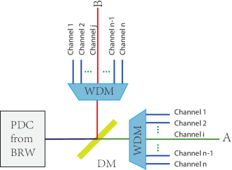
Finally, we use the scheme in Figure 9 for generating polarization entangled states with multiple spectral bands that are free from temporal delay compensation [17, 18, 33]. In the absence of background light, the density matrix of the polarization entangled state takes the form [19],
| (6) |
in which and describe a single-photon state with horizontal polarization (signal) and vertical polarization (idler), respectively. In Equation 6 the diagonal elements take the form and with being a normalization constant, whereas the off-diagonal elements are described as
| (7) |
with
| (8) |
and
| (9) |
In Equation 8 and Equation 9 and describe the amplitudes of Gaussian bandpass filters with central angular frequencies and and bandwidths and , respectively, while and are the transmittance and reflectance of the dichroic mirror in Figure 9, for which . For simplicity, we take and as step functions having the cut-off wavelength at the degeneracy.
Due to the normalization, the diagonal elements of the density matrix in Equation 6 obey the relation , while the off-diagonal elements and , called coherences, can be used to quantify the amount of entanglement. Ideally, for a maximally entangled state . Thus, the behavior of the -parameter is especially interesting, because any decrease in its value means a reduced amount of created entanglement.
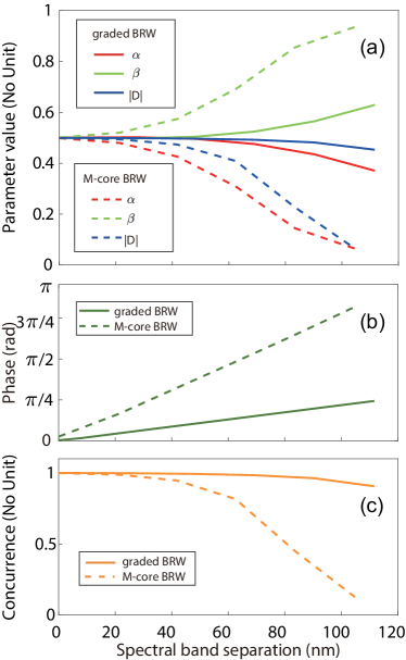
In Figure 10 we show the density matrix elements from Equation 6 for the two investigated BRW structures with respect to the separation of the signal and idler spectral bands. We simulate the PDC processes at the degeneracy and and use narrowband spectral Gaussian filters with a FWHM of for creating entangled photon pairs in different spectral bands obeying the energy conservation . From Figure 10(a) we see that the density matrix elements calculated for the graded BRW structure are more robust against a large spectral band separation than those calculated for the M-core BRW structure. Additionally, the phase of the -parameter in Figure 10(b) is varying less for the graded BRW structure than for the M-core BRW structure. This indicates that the entangled states generated in different frequency bands have more uniform characteristics if the average DGD is small. Finally, in Figure 10(c) we quantify the achievable entanglement in both BRW structures with the concurrence [44].
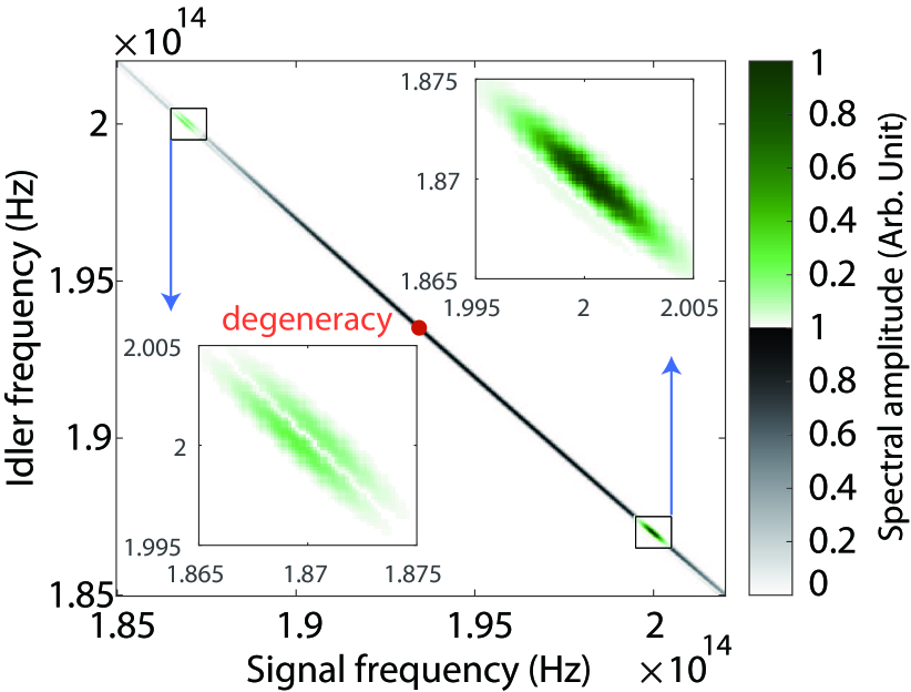
Apart from the temporal walk-off of signal and idler, also their spectral overlap plays a crucial role in the generation of polarization entanglement. The asymmetry of the JSA with respect to the degeneracy as shown in Figure 11 for the M-core BRW structure is the reason for the highly imbalanced diagonal elements and in Figure 10(a) and the low concurrence in Figure 10(c). To summarize, our results show that the layer parameters of BRWs have to be carefully designed in order to optimize their performance in quantum optical applications.
6 Conclusion
Direct engineering of the spectro-temporal properties of PDC emission is of great importance for preparing quantum optical states with high quality. We investigated how the shape and the material composition of a Bragg-reflection waveguide affect its optical properties, like the phasematching wavelength and the group indices of the interacting modes and showed that our design is to a well-manageable degree tolerant against variations. We further investigated, how the effective group refractive index difference between signal and idler can be manipulated. Our BRW design results in good spectral and temporal overlap between signal and idler, which makes our structure well-suited for different quantum optics tasks both at the degeneracy and far away from it.
Acknowledgements
This work was supported by the Austrian Science Fund (FWF) through the project nos. I-2065 and J-4125, the DFG project no. SCHN1376/2-1, the State of Bavaria, China Scholarship Council project no. 201503170272, and Natural Science Foundation of Hunan Province of China project no. 2018JJ2467.
References
References
- [1] L. Caspani, C. Xiong, B. J. Eggleton, D. Bajoni, M. Liscidini, M. Galli, R. Morandotti, and D. J. Moss. Integrated sources of photon quantum states based on nonlinear optics. Light Sci. Appl., 6:e17100, 2017.
- [2] F. Flamini, N. Spagnolo, and F. Sciarrino. Photonic quantum information processing: a review. Rep. Prog. Phys,. 82 016001, 2019.
- [3] C. K. Hong, Z. Y. Ou, and L. Mandel. Measurement of subpicosecond time intervals between two photons by interference. Phys. Rev. Lett., 59:2044, 1987.
- [4] P. G. Evans, R. S. Bennink, W. P. Grice, T. S. Humble, and J. Schaake. Bright source of spectrally uncorrelated polarization-entangled photons with nearly single-mode emission. Phys. Rev. Lett., 105:253601, 2010.
- [5] E. Y. Zhu, Z. Tang, L. Qian, L. G. Helt, M. Liscidini, J. E. Sipe, C. Corbari, A. Canagasabey, M. Ibsen, and P. G. Kazansky. Direct generation of polarization-entangled photon pairs in a poled fiber. Phys. Rev. Lett., 108:213902, 2012.
- [6] N. Bruno, A. Martin, T. Guerreiro, B. Sanguinetti, and R. T. Thew. Pulsed source of spectrally uncorrelated and indistinguishable photons at telecom wavelengths. Opt. Express, 22:17246, 2014.
- [7] D. Kang, A. Pang, Y., Zhao, and A. S. Helmy. Two-photon quantum state engineering in nonlinear photonic nanowires. J. Opt. Soc. Am. B, 31:1581, 2014.
- [8] K. Laiho, A. Christ, K. N. Cassemiro, and Ch. Silberhorn. Testing spectral filters as gaussian quantum optical channels. Opt. Lett., 36:1476, 2011.
- [9] N. Bruno, E. Z. Cruzeiro, A. Martin, and R. T. Thew. Simple, pulsed, polarization entangled photon pair source. Opt. Comm., 327:3, 2014.
- [10] J. W. Silverstone, D. Bonneau, K. Ohira, N. Suzuki, H. Yoshida, N. Iizuka, M. Ezaki, C. M. Natarajan, M. G. Tanner, R. H. Hadfield, V. Zwiller, G. D. Marshall, J. G. Rarity, J. L. O’Brien, and M. G. Thompson. On-chip quantum interference between silicon photon-pair sources. Nature Photon., 8:104, 2014.
- [11] J. M. Donohue, M. Mastrovich, and K. J. Resch. Spectrally engineering photonic entanglement with a time lens. Phys. Rev. Lett., 117:243602, 2016.
- [12] L. J. Wright, M. Karpinski, C. Söller, and B. J. Smith. Spectral shearing of quantum light pulses by electro-optic phase modulation. Phys. Rev. Lett., 118:023601, 2017.
- [13] M. Grimau Puigibert, G. H. Aguilar, Q. Zhou, F. Marsili, M. D. Shaw, V. B. Verma, S. W. Nam, D. Oblak, and W. Tittel. Heralded single photons based on spectral multiplexing and feed-forward control. Phys. Rev. Lett., 119:083601, 2017.
- [14] V. Ansari, E. Roccia, M. Santandrea, M. Doostdar, C. Eigner, L. Padberg, I. Gianani, M. Sbroscia, J. M. Donohue, L. Mancino, M. Barbieri, and C. Silberhorn. Heralded generation of high-purity ultrashort single photons in programmable temporal shapes. Opt. Express, 26:2764, 2018.
- [15] S. V. Zhukovsky, L. G. Helt, D. Kang, P. Abolghasem, A. S. Helmy, and J. E. Sipe. Generation of maximally-polarization-entangled photons on a chip. Phys. Rev. A, 85:013838, 2012.
- [16] R. T Horn, P. Kolenderski, D. Kang, P. Abolghasem, C. Scarcella, A. Della Frera, A. Tosi, L. G. Helt, S. V. Zhukovsky, J. E. Sipe, et al. Inherent polarization entanglement generated from a monolithic semiconductor chip. Sci. Rep., 3, 2013.
- [17] D. Kang, A. Anirban, and A. S. Helmy. Monolithic semiconductor chips as a source for broadband wavelength-multiplexed polarization entangled photons. Opt. Express, 24:15160, 2016.
- [18] C. Autebert, J. Trapateau, A. Orieux, A. Lemaître, C. Gomez-Carbonell, E. Diamanti, I. Zaquine, and S. Ducci. Multi-user quantum key distribution with entangled photons from an AlGaAs chip. Quantum Sci. Tech., 1:01LT02, 2016.
- [19] A. Schlager, B. Pressl, K. Laiho, H. Suchomel, M. Kamp, S. Höfling, C. Schneider, and G. Weihs. Temporally versatile polarization entanglement from Bragg reflection waveguides. Opt. Lett., 42:2102, 2017.
- [20] L. Lanco, S. Ducci, J.-P. Likforman, X. Marcadet, J. A. W. Van Houwelingen, H. Zbinden, G. Leo, and V. Berger. Semiconductor waveguide source of counterpropagating twin photons. Phys. Rev. Lett., 97:173901, 2006.
- [21] P. Sarrafi, E. Y. Zhu, K. Dolgaleva, B. M. Holmes, D. C. Hutchings, J. S. Aitchison, and L. Qian. Continuous-wave quasi-phase-matched waveguide correlated photon pair source on a III–V chip. Appl. Phys. Lett., 103:251115, 2013.
- [22] R. Horn, P. Abolghasem, B. J. Bijlani, D. Kang, A. S. Helmy, and G. Weihs. Monolithic source of photon pairs. Phys. Rev. Lett., 108:153605, 2012.
- [23] B. R. West and A. S. Helmy. Analysis and design equations for phase matching using Bragg reflector waveguides. IEEE J. Quantum Electron., 12:431, 2006.
- [24] A. S. Helmy. Phase matching using Bragg reflection waveguides for monolithic nonlinear optics applications. Opt. Express, 14:1243, 2006.
- [25] S. Gehrsitz, F. K. Reinhart, C. Gourgon, N. Herres, A. Vonlanthen, and H. Sigg. The refractive index of AlxGa1-xAs below the band gap: accurate determination and empirical modeling. J. Appl. Phys., 87:7825, 2000.
- [26] B. Pressl, T. Günthner, K. Laiho, J. Geßler, M. Kamp, S. Höfling, C. Schneider, and G. Weihs. Mode-resolved fabry-perot experiment in low-loss Bragg-reflection waveguides. Opt. Express, 23:33608, 2015.
- [27] K. Laiho, B. Pressl, A. Schlager, H. Suchomel, M. Kamp, S. Höfling, C. Schneider, and G. Weihs. Uncovering dispersion properties in semiconductor waveguides to study photon-pair generation. Nanotechnology, 27:434003, 2016.
- [28] M. Misiaszek, A. Gajewski and P. Kolenderski Dispersion measurement method with down conversion process. J. Phys. Commun. 2:065014, 2018.
- [29] B. Pressl, K. Laiho, H. Chen, T. Günthner, A. Schlager, S. Auchter, H. Suchomel, M. Kamp, S. Höfling, C. Schneider, and G. Weihs. Semi-automatic engineering and tailoring of high-efficiency Bragg-reflection waveguide samples for quantum photonic applications. Quantum Sci. Tech., 3:024002, 2018.
- [30] COMSOL Multiphysics®, www.comsol.com, COMSOL AB, Stockholm, Sweden.
- [31] B. Bijlani, P. Abolghasem, and A. S. Helmy Second harmonic generation in ridge Bragg reflection waveguides. Appl. Phys. Lett., 92:101124, 2008.
- [32] P. Abolghasem, J. Han, B. J. Bijlani, A. Arjmand and A. S. Helmy Continuous-wave second harmonic generation in Bragg reflection waveguides. Opt. Express, 17:9460, 2009.
- [33] C. Chen, E. Y. Zhu, A. Riazi, A. V. Gladyshev, C. Corbari, M. Ibsen, P. G. Kazansky, and L. Qian. Compensation-free broadband entangled photon pair sources. Opt. Express, 25:22667, 2017.
- [34] T. Günthner, B. Pressl, K. Laiho, J. Geßler, S. Höfling, M. Kamp, C. Schneider, and G. Weihs. Broadband indistinguishability from bright parametric downconversion in a semiconductor waveguide. J.Opt., 17:125201, 2015.
- [35] P. Abolghasem, J. Han, B. J. Bijlani, A. Arjmand, and A. S. Helmy. Highly efficient second-harmonic generation in monolithic matching layer enhanced AlxGa1-xAs Bragg reflection waveguides. IEEE Photon. Technol. Lett., 21:1462, 2009.
- [36] W. P. Grice, A. B. U’Ren, and I. A. Walmsley. Eliminating frequency and space-time correlations in multiphoton states. Phys. Rev. A, 64:063815, 2001.
- [37] W. P. Grice and I. A. Walmsley. Spectral information and distinguishability in type-II down-conversion with broadband pump. Phys. Rev. A, 56:1627, 1997.
- [38] M. Avenhaus, M. V. Chekhova, L. A. Krivitsky, G. Leuchs, and Ch. Silberhorn. Experimental verification of high spectral entanglement for pulsed waveguided spontaneous parametric down-conversion. Phys. Rev. A, 79:043836, 2009.
- [39] S. V. Zhukovsky, L. G. Helt, D. Kang, P. Abolghasem, A. S. Helmy, and J. E. Sipe. Analytical description of photonic waveguides with multilayer claddings: Towards on-chip generation of entangled photons and bell states. Opt. Comm., 301:127, 2013.
- [40] R.-B. Jin, R. Shiina, and R. Shimizu. Quantum manipulation of biphoton spectral distributions in a 2D frequency space toward arbitrary shaping of a biphoton wave packet. Opt. Express, 26:21153, (2018).
- [41] F. Graffitti, P. Barrow, M. Proietti, D. Kundys, and A. Fedrizzi. Independent high-purity photons created in domain-engineered crystals. Optica, 5:514, 2018.
- [42] H. Chen, S. Auchter, M. Prilmüller, A. Schlager, T. Kauten, K. Laiho, B. Pressl, H. Suchomel, M. Kamp, S. Höfling, C. Schneider, and G. Weihs. Time-bin entangled photon pairs from Bragg-reflection waveguides. APL Photonics, 3:080804, (2018).
- [43] A. Eckstein and C. Silberhorn. Broadband frequency mode entanglement in waveguided parametric downconversion. Opt. Lett., 33:1825, 2008.
- [44] S. Hill and W. K. Wootters. Entanglement of a pair of quantum bits. Phys. Rev. Lett., 78:5022, 1997.