Microstructural-defect-induced Dzyaloshinskii-Moriya interaction
Abstract
The antisymmetric Dzyaloshinskii-Moriya interaction (DMI) plays a decisive role for the stabilization and control of chirality of skyrmion textures in various magnetic systems exhibiting a noncentrosymmetric crystal structure. A less studied aspect of the DMI is that this interaction is believed to be operative in the vicinity of lattice imperfections in crystalline magnetic materials, due to the local structural inversion symmetry breaking. If this scenario leads to an effect of sizable magnitude, it implies that the DMI introduces chirality into a very large class of magnetic materials—defect-rich systems such as polycrystalline magnets. Here, we show experimentally that the microstructural-defect-induced DMI gives rise to a polarization-dependent asymmetric term in the small-angle neutron scattering (SANS) cross section of polycrystalline ferromagnets with a centrosymmetric crystal structure. The results are supported by theoretical predictions using the continuum theory of micromagnetics. This effect, conjectured already by Arrott in 1963, is demonstrated for nanocrystalline terbium and holmium (with a large grain-boundary density), and for mechanically-deformed microcrystalline cobalt (with a large dislocation density). Analysis of the scattering asymmetry allows one to determine the defect-induced DMI constant, for Tb at . Our study proves the generic relevance of the DMI for the magnetic microstructure of defect-rich ferromagnets with vanishing intrinsic DMI. Polarized SANS is decisive for disclosing the signature of the defect-induced DMI, which is related to the unique dependence of the polarized SANS cross section on the chiral interactions. The findings open up the way to study defect-induced skyrmionic magnetization textures in disordered materials.
The Dzyaloshinskii-Moriya interaction (DMI) Dzyaloshinsky (1958); Moriya (1960) has recently moved again into the focus of condensed-matter research in the context of numerous observations of skyrmion lattices in various magnetic materials (see, e.g., Refs. Mühlbauer et al., 2009; Pfleiderer et al., 2010; Münzer et al., 2010; Yu et al., 2010, 2011; Heinze et al., 2011; Adams et al., 2012; Seki et al., 2012; Milde et al., 2013; Nagaosa and Tokura, 2013; Tokunaga et al., 2015; Boulle et al., 2016; Nayak et al., 2017; Kurumaji et al., 2017; Chacon et al., 2018 and references therein). The origin of the DMI is related to relativistic spin-orbit coupling, and in inversion asymmetric crystal-field environments it gives rise to antisymmetric magnetic interactions Bogdanov and Yablonskiĭ (1989); Bogdanov and Hubert (1994); Bogdanov et al. (2005); Rössler et al. (2006). In most of the studies published so far, the DMI is the essential ingredient for the stabilization of various types of skyrmion textures, and its origin is related to the noncentrosymmetric crystal structures of the materials under study, or to the breaking of structural inversion symmetry at the interfaces in ultrathin film architectures (e.g., Refs. Heinze et al. (2011); Yu et al. (2011); Boulle et al. (2016)).
However, it has already been conjectured by Arrott in 1963 that lattice imperfections in the microstructure of ferromagnetic and antiferromagnetic materials are accompanied by the presence of local chiral DMI couplings due to the breaking of inversion symmetry at defect sites Arrott (1963). Arrott suggested that the DMI is present in the vicinity of any lattice defect and that it gives rise to inhomogeneous magnetization states: for two magnetic ions which are ferromagnetically coupled by the isotropic exchange interaction, the DMI, when acting on the exchange path, produces an antiferromagnetic component, while for the two ions being antiferromagnetically aligned by isotropic exchange, the DMI causes a ferromagnetic component. In a sense, microstructural defects are supposed to act as a source of additional local chiral interactions, similar to the above mentioned intrinsic DMI in noncentrosymmetric crystal structures. Therefore, if the above sketched scenario is valid, it is important to realize that the DMI is generally present in defect-rich magnetic materials, even in highly symmetric centrosymmetric lattices, where the “usual” intrinsic DMI term vanishes.
Research along these lines has previously been conducted by Fedorov et al. (1997), who studied the impact of torsional-strain-induced DMI couplings near dislocations on the helix domain populations in Ho metal. Similarly, Grigoriev et al. (2008) investigated the field-induced chirality in the helix structure of Dy/Y multilayer films and provided evidence for interface-induced DMI. Beck and Fähnle (2010) combined ab-initio density functional electron theory with a micromagnetic model to study the DMI vectors arising from a fabrication-induced perpendicular strain gradient in a film of bcc Fe. Butenko and Rößler (2013) have developed a micromagnetic model for dislocation-induced DMI couplings. These authors considered a disk-like film element with a screw dislocation at its center and showed that the associated defect-induced DMI leads to a chirality selection of the vortex state.
Supported by theory Michels et al. (2016), we provide here experimental evidence for the generic impact of the DMI on the spin microstructure of polycrystalline defect-rich ferromagnets. Examples for such systems are nanomagnets, which are characterized by a large volume fraction of internal interfaces (e.g., grain boundaries), and mechanically-deformed metals containing a large density of dislocations. In the vicinity of both types of lattice imperfections—interfaces and dislocations—inversion symmetry is likely to be broken, so that the DMI may be operative. Defect-related DMI is therefore expected to manifest in other measurements as well (e.g., magnetization data), however, the technique of polarized small-angle neutron scattering (SANS) is probably the only one which is able to directly disclose its signature: this is brought about by the unique dependence of the polarized SANS cross section on the chiral interactions. In this paper we report the results of polarized SANS experiments on nanocrystalline Tb and Ho, and on mechanically-deformed Co (see Methods section), all of which have a centrosymmetric crystal structure in the single-crystalline ground state.
Based on micromagnetic theory using the DMI energy of cubic symmetry (e.g., Rössler et al. (2006)),
| (1) |
we have theoretically investigated in Ref. Michels et al., 2016 the impact of the DMI on the magnetization distribution and on the ensuing magnetic SANS cross section. In addition to the DMI energy, we have taken into account the energies due to the isotropic exchange interaction, magnetic anisotropy, and the magnetostatic interaction. The central prediction is that the difference between the polarized “spin-up” and “spin-down” SANS cross sections (for the scattering geometry with the incoming neutron beam perpendicular to the applied magnetic field) is proportional to the so-called chiral function , which contains the lattice-defect-induced effect related to the DMI (compare Eq. (6) in the Methods section):
| (2) |
where denotes the anisotropy-field Fourier coefficient, and is the Fourier coefficient of the longitudinal magnetization. These functions characterize the strength and spatial structure of, respectively, the magnetic anisotropy field (with correlation length ) and of the local saturation magnetization (with correlation length ); is a known function of and of the internal magnetic field (: demagnetizing factor); and represent micromagnetic length scales which characterize, respectively, the size of inhomogeneously magnetized regions around defects and the range of the DMI (: exchange-stiffness constant; : DMI constant; , compare Fig. 5). The negative of the function is plotted in Fig. 6 in Michels et al. (2016); there, it is seen that is asymmetric in , which is due to the defect-induced DMI: at small fields, when the anisotropy term in the numerator of Eq. (2) dominates, two extrema parallel and antiparallel to the field axis are observed, whereas at larger fields, when the magnetostatic term comes into play, additional maxima and minima appear approximately along the detector diagonals. Moreover, we note that vanishes for purely real magnetization Fourier components (irrespective of the value of the applied magnetic field), and at complete magnetic saturation when (compare Eq. (5) in Methods section).
Evaluating Eq. (2) along the horizontal direction ( and ) and assuming that depends only on the magnitude of , we have (independent of )
| (3) |
which can be used to analyze experimental data. Note that for , which allows its clear separation from the nuclear-magnetic interference term in Eq. (6) (provided that both and are isotropic). In the analysis below, we assume that the anisotropy-field Fourier coefficient is described by a squared Lorentzian, , where is the mean-square anisotropy field, and denotes the correlation length of the anisotropy field. For an idealized nanocrystalline ferromagnet, where each grain is a single crystal and the anisotropy field jumps randomly in direction at grain boundaries due to the changing set of crystallographic easy axes, the correlation length is expected to be related to the average grain size. Mechanical deformation of Co results in an increased density of dislocation structures, which, by means of magnetoelastic coupling, gives rise to inhomogeneous magnetization states and to a concomitant magnetic SANS contrast Kronmüller and Fähnle (2003); in this case, characterizes the average extension of the dislocation.
Before discussing the experimental results we find it appropriate to pause and to briefly examine how defects in the microstructure of a magnetic material (e.g., vacancies, dislocations, grain boundaries, pores) are related to the diffuse magnetic SANS cross section. The following considerations are restricted to the mesoscopic length scale which is accessible by the conventional SANS method (), as it is suitable for a description within the micromagnetic continuum picture. The mechanisms by which nanoscale spin disorder in magnetic materials is generated are essentially related to (i) spatial variations in the magnetic anisotropy field , and to (ii) spatial variations in the magnetic materials parameters, most notably the local saturation magnetization . Both sources of magnetization inhomogeneities—modeling the effect of the defects—are taken into account in the magnetic SANS theory Michels et al. (2016). To be more specific, forces due to the distortion of the crystal lattice in the vicinity of a microstructural defect tend to rotate the local magnetization vector field along the main axes of the system of internal stresses (so-called magnetoelastic coupling), while magnetocrystalline anisotropy tries to pull the magnetic moments along the principal axes of the crystal Brown Jr. (1940). Likewise, nanoscale spatial variations of the saturation magnetization, exchange, or anisotropy constants (e.g., at internal interfaces in a magnetic nanocomposite or in a nanoporous ferromagnet) give rise to inhomogenous magnetization states, which represent a contrast for magnetic SANS. It is also important to emphasize that the adjustment of the magnetization along the respective local “easy” axes does not occur abruptly, i.e., on a scale of the interatomic spacing, but requires a more extended range. This is a consequence of the quantum-mechanical exchange interaction, which spreads out local perturbations in the magnetization (at the defect core) over larger distances. The size of such spin inhomogeneities is characterized by the micromagnetic exchange length Brown Jr. (1940); Kronmüller and Seeger (1961), which varies continuously with the applied field and takes on values between about , a size regime which is routinely accessible by SANS (e.g., Michels et al. (2003); Mirebeau et al. (2018)). As we will show below, the defect-related DMI introduces chirality into the system and renders the spin distribution around the defect cores asymmetric.
Figure 1 depicts the results of polarized SANS experiments on nanocrystalline Tb (average crystallite size: smd ) in the ferromagnetic state at and at an applied magnetic field of tbp . We emphasize that it is a well-documented result in the literature that the magnetic properties of nanocrystalline heavy rare-earth metals are strongly affected by a small crystallize size, i.e., by an associated large volume fraction of interfaces Michels et al. (2002); Weissmüller et al. (2004); Michels et al. (2011); Döbrich et al. (2012); Szary et al. (2016) (see also Fig. 2 in smd ). Both spin-resolved data sets [Fig. 1(a)] and [Fig. 1(b)] are characterized by a maximum of the scattering intensity along the horizontal applied-field direction. This is the signature of spin-misalignment scattering due to the presence of transversal magnetization components [cf. the term in Eq. (Spin-polarized SANS cross section)]. The difference between the two spin-resolved SANS cross sections, [Fig. 1(c)], clearly exhibits an asymmetric contribution related to the chiral function [compare Eq. (6)]. The asymmetry is most pronounced along the horizontal direction, which by comparison to the theoretical prediction [Eq. (2)] can be attributed to the anisotropy-field term . Data taken at smaller momentum transfers additionally show the “usual” symmetric -type anisotropy (with maxima at and ), which is due to the polarization-dependent nuclear-magnetic interference term in the SANS cross section (see Fig. 4 in smd ).
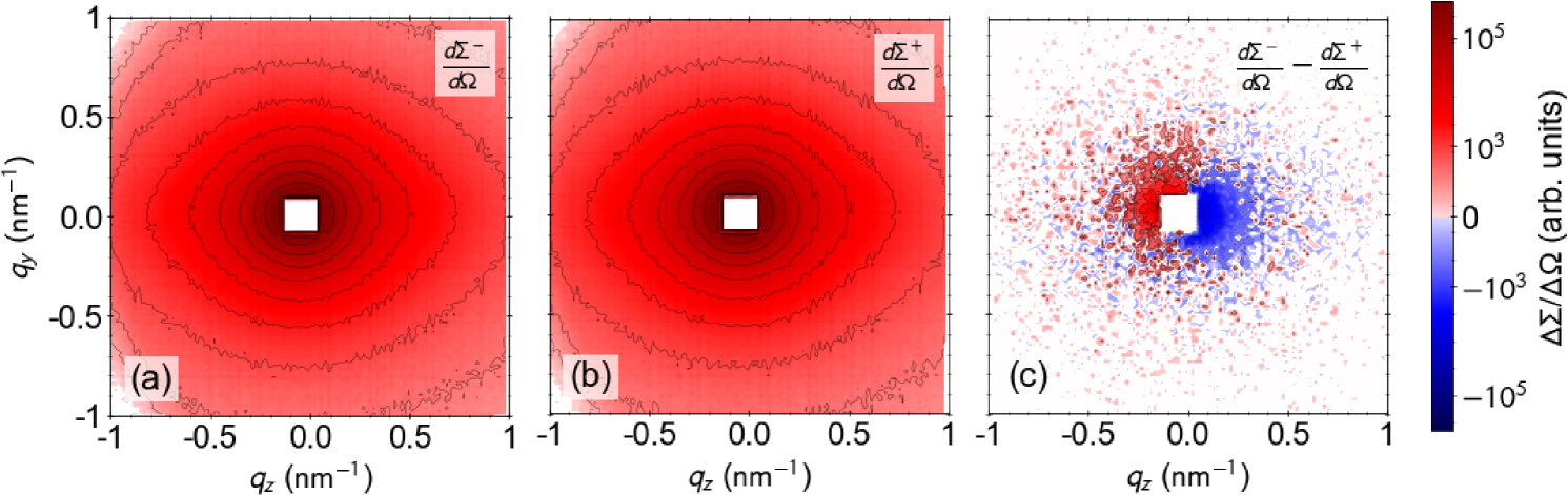
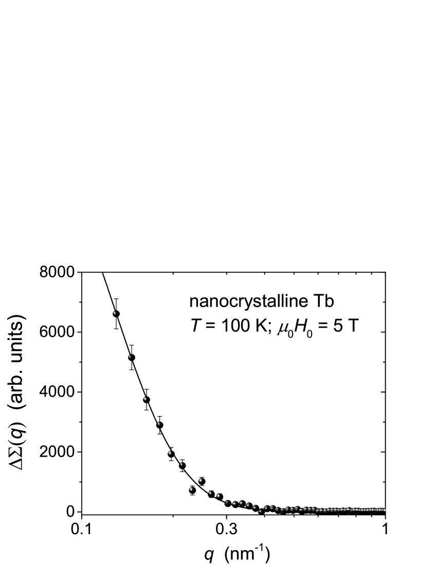
Figure 2 displays the angular average of the data from Fig. 1(c) along the horizontal direction. By performing a weighted nonlinear least-squares fit of the resulting data to Eq. (3) (solid line in Fig. 2), the following parameters are obtained: ; ; . The value for is comparable to bulk DMI values (e.g., Iguchi et al. (2015); Seki et al. (2016)), the effective -value is slightly increased but still within the range of experimental data Kronmüller and Fähnle (2003); Weissmüller et al. (2004), while the correlation length of the anisotropy-field is smaller than the average crystallite size of the Tb sample ( smd ). The latter finding indicates that there is a significant spin disorder within the grains. This is in agreement with the results of an earlier unpolarized SANS study Weissmüller et al. (2004), which has found that up to applied fields of several Tesla the magnetization remains “locked in” to the basal planes of the hcp crystal lattice of each individual crystallite, but that the in-plane orientation of the spins is highly nonuniform within each grain.
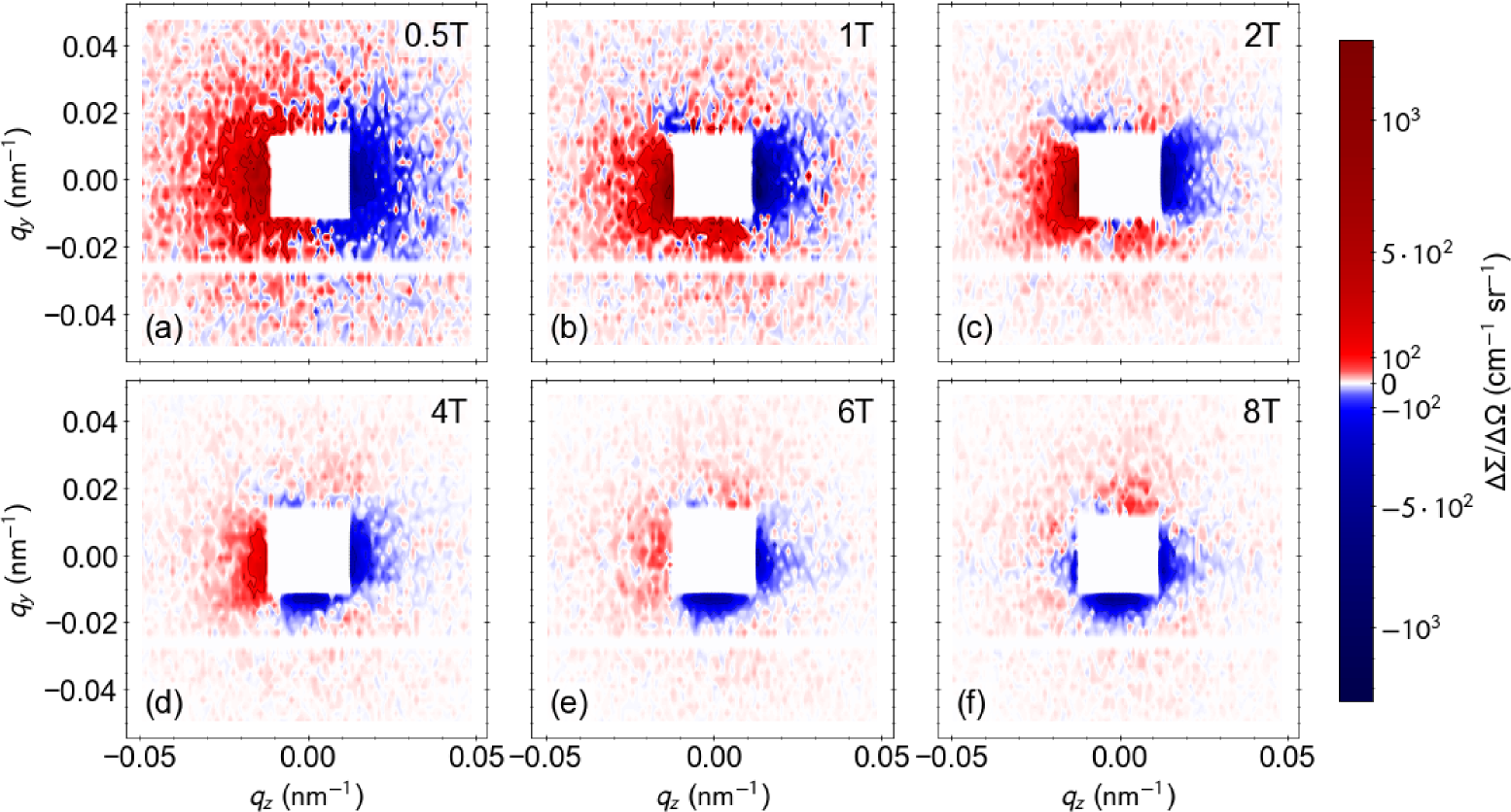
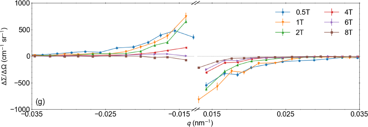
Magnetic-field-dependent data of the deformed Co sample at room temperature are shown in Fig. 3 with the magnetic field applied parallel to the rolling direction. Inspection of the Co magnetization curves (Fig. 3 in smd ) clearly shows that all of the displayed field values fall into the approach-to-saturation regime, where the predictions of the micromagnetic SANS theory are valid Michels et al. (2016). The results confirm, in agreement with the theory, that with increasing field the asymmetry decreases and eventually vanishes for fields in excess of ; note that for (compare Eq. (5) in the Methods section).
As shown in the Supplemental Material (Fig. 5 in smd ), polarized SANS data on nanocrystalline Ho (grain size: ) at and also reveal the scattering asymmetry. At this temperature Ho exhibits a conical ferromagnetic spin structure Legvold (1980). This result, together with the data on Tb and Co, underlines the generic character of the DMI asymmetry for polycrystalline magnetic materials having a centrosymmetric crystal structure.
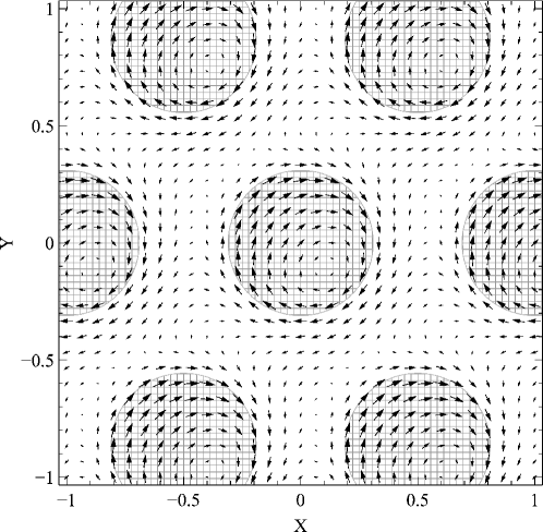
In the following we will discuss the possible mesoscale real-space spin structure which lies at the heart of the present SANS data. Recently, Mirebeau et al. (2018) have also provided a SANS study, albeit using unpolarized neutrons, of a disordered magnetic material, the reentrant spin glass . Supported by the results of Monte Carlo simulations of a two-dimensional lattice structure with competing ferromagnetic and antiferromagnetic exchange interactions, these authors have suggested the existence of vortex-like chiral spin structures. While vortices are ubiquitous in magnetism and can very well be at the origin of the underlying mesoscopic spin structure, our data directly show that there is a general symmetry breaking in the samples (besides the one induced by the external field) resulting in a dominant overall chirality of the spin texture. In the case of the Co sample the reason for such a symmetry breaking is obviously related to the mechanical deformation (similar to the work by Fedorov et al. (1997)). Regarding the nondeformed samples (Tb and Ho), the vorticity in the magnetization texture appears only because the samples are intrinsically inhomogeneous. The shape of the chiral structures in our samples is not an equilibrium property of the uniform magnet, but directly reflects the shape of the magnetic inhomogeneities. This is demonstrated in Fig. 4, which displays the numerically computed real-space spin structure around defects in the presence of DMI (see smd for details). An asymmetry in the transversal spin configuration clearly becomes evident, which is a consequence of the DMI: setting produces a symmetric magnetization pattern with a maximum transversal spin deviation located at the centers of the defects (due to the perturbing effect of the magnetic anisotropy field). By contrast, for , it is seen that the chirality in the magnetization texture manifests itself at/near the boundaries of the inhomogeneities (boundaries of the shaded areas in Fig. 4), precisely where one would expect the antisymmetric DMI to appear. Thus, the value of the DMI constant obtained from the SANS experiment should mainly reflect this emergent DMI strength.
To summarize, using polarized small-angle neutron scattering (SANS) and micromagnetic theory we have provided evidence that the Dzyaloshinskii-Moriya interaction (DMI) which is due to the lack of structural inversion symmetry at microstructural-defect sites gives rise to an asymmetry in the polarized SANS cross section. This has been demonstrated for the cases of nanocrystalline terbium and holmium, and for mechanically-deformed microcrystalline cobalt, all of which have a centrosymmetric crystal structure. To the best of our knowledge, our study proves for the first time the generic relevance of the DMI for the spin microstructure of defect-rich ferromagnets, where this interaction introduces chirality into the system. Consequently, the effect should also show up in other magnetic measurements as well, for instance, in the approach-to-saturation regime of a magnetization curve. However, due to the unique dependence of the polarized neutron scattering cross section on the chiral function, the SANS method is particularly powerful for revealing the fingerprint of the defect-induced DMI. An analytical theoretical framework for determining the DMI constant, which is a key parameter in the search for skyrmion-hosting materials and for the elucidation of the potential of skyrmions for high-density magnetic data storage, has been established. Our findings may provide an impetus towards the investigation of defect-induced local chiral spin textures in polycrystalline and disordered materials, such as spin glasses. Since the strength of the effect scales with the spin-orbit coupling, one may combine low-anisotropy (e.g., Gd3+ which is a pure -state ion) with high-anisotropy materials.
Methods
Sample
A circular disk-shaped nanocrystalline Tb sample with a diameter of and a thickness of was synthesized by the inert-gas condensation technique, as described in detail in Refs. Michels et al., 2002; Weissmüller et al., 2004; Michels et al., 2011; Döbrich et al., 2012; Szary et al., 2016. The average crystallite size of the as-prepared nanocrystalline Tb sample was determined by analysis of wide-angle x-ray diffraction data and found to be smd . The results of the structural and magnetic characterization of the nanocrystalline inert-gas-condensed Ho sample () are reported in Ref. Szary et al., 2016. Commercially available high-purity polycrystalline Co pieces (purity: ) were arc-melted in an argon atmosphere. A thin disk was cut from the as-prepared sample; cold-rolling resulted in a reduction of the thickness of the disk from to . In the SANS experiment, the rolling direction was oriented parallel to the applied magnetic field. Vibrating sample and SQUID magnetometry was used to measure hysteresis loops and ac susceptibility smd .
SANS Experiment
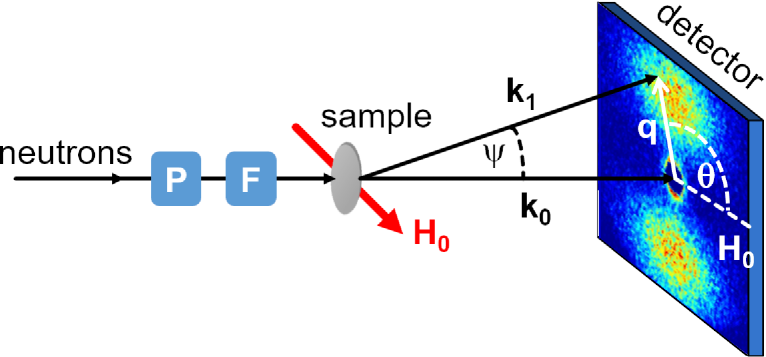
The neutron experiment was conducted at the D33 instrument at the Institut Laue-Langevin, Grenoble, France Dewhurst et al. (2016); Michels et al. (2018). We used polarized incident neutrons with a mean wavelength of and a wavelength broadening of (FWHM); for the runs on deformed Co, the wavelength was increased to () in order to access smaller momentum transfers. The external magnetic field was provided by a cryomagnet and applied perpendicular to the wave vector of the incident neutron beam; see Fig. 5 for a schematic drawing of the experimental neutron setup. The beam was polarized by a remanent FeSi supermirror transmission polarizer (), and a radio-frequency (rf) spin flipper allowed us to reverse the initial neutron polarization. The flipping efficiency of the rf flipper was , and the polarizer efficiency was at and at . Further neutron experiments under similar conditions have been performed at the SANS I instrument at the Paul Scherrer Institute, Villigen, Switzerland Kohlbrecher and Wagner (2000). For SANS data reduction the GRASP software package was used Dewhurst (2018).
Spin-polarized SANS cross section
Neglecting nuclear spin-dependent scattering, the two half-polarized elastic differential SANS cross sections for the perpendicular scattering geometry () can be expressed as Maleev et al. (1963); Blume (1963); Michels and Weissmüller (2008); Mühlbauer et al. (2018):
| (4) |
where the chiral function is given by
| (5) |
In Eq. (Spin-polarized SANS cross section), is the scattering volume, the constant relates the atomic magnetic moment to the atomic magnetic scattering length , and denote, respectively, the Fourier transforms of the nuclear scattering-length density and of the magnetization vector field , is the angle between and , so that in small-angle approximation, , and the asterisks “” mark the complex-conjugated quantity. Note that for (when ) and for purely real magnetization Fourier components. The efficiency of the polarizer is denoted by , and is the efficiency of the spin flipper ( for flipper off and for flipper on). In our data analysis we have neglected the polarization-dependent terms in Eq. (Spin-polarized SANS cross section). These contributions average out for statistically-isotropic polycrystalline magnetic materials, since there are no correlations between spatial variations in the nuclear density and in the transversal magnetization components (note that for such a material). The difference between flipper-on (“”) and flipper-off (“”) SANS cross sections reads:
| (6) |
Influence of inelastic SANS
Typical SANS instrumentation does not allow for energy analysis of the scattered neutrons and the measurable quantity is the energy-integrated macroscopic differential scattering cross section at scattering vector . Since the asymmetry which we report is due to the effect of the DMI on the static magnetic microstructure, which is probed by elastic scattering, it is necessary to show that inelastic magnon scattering is suppressed in the small-angle regime under the conditions of our experiment. In this context we emphasize that the here reported DMI asymmetry is very much different than the so-called “left-right” asymmetry Okorokov et al. (1986); Grigoriev et al. (2015), which has its origin in inelastic spin-wave scattering. In Ref. Michels and Weissmüller (2008) it was shown that the requirements of conservation of momentum and energy upon absorption or emission of a magnon cannot be satisfied simultaneously for any scattering vector in the small-angle regime when the applied magnetic field exceeds the critical value:
| (7) |
where , is the spin-wave stiffness constant, and denotes the gap energy in the (simplified) spin-wave dispersion relation (: Planck’s constant divided by ; : neutron mass; : g-factor; : Bohr magneton). Inserting typical values of these parameters for Tb Weissmüller et al. (2004) and Co Michels and Weissmüller (2008), one can see that inelastic magnon scattering is suppressed at the applied-field values of the present experiment ( for Co and for Tb at, respectively, zero gap energy).
Acknowledgements
A.Mi. and D.M. thank the National Research Fund of Luxembourg for financial support (Project No. INTER/DFG/12/07). This work is based on experiments performed at the Institut Laue-Langevin, Grenoble, France, and at the Swiss spallation neutron source SINQ, Paul Scherrer Institute, Villigen, Switzerland. We thank Sebastian Mühlbauer for the critical reading of the manuscript.
Author Contributions
A.Mi. conceived and designed the study and wrote the manuscript. A.Mi., D.M., I.T., A.Ma., M.B., P.B., Y.Q., P.H., J.K., and D.H. performed and analyzed the polarized neutron-scattering experiments. D.M., I.T., A.Ma., I.P., R.B., J.R.F., and L.F.B. carried out sample synthesis as well as the magnetization and x-ray diffraction experiments. A.Mi. and K.L.M. are responsible for the micromagnetic part of the paper; K.L.M. performed the micromagnetic calculation of the real-space magnetization. All authors discussed the results and commented on the manuscript.
Additional Information
Supplementary information accompanies this paper at…
Competing Interests:
The authors declare no competing interests.
References
- Dzyaloshinsky (1958) I. Dzyaloshinsky, “A thermodynamic theory of “weak” ferromagnetism of antiferromagnets,” J. Phys. Chem. Solids 4, 241–255 (1958).
- Moriya (1960) T. Moriya, “Anisotropic superexchange interaction and weak ferromagnetism,” Phys. Rev. 120, 91–98 (1960).
- Mühlbauer et al. (2009) S. Mühlbauer, B. Binz, F. Jonietz, C. Pfleiderer, A. Rosch, A. Neubauer, R. Georgii, and P. Böni, “Skyrmion Lattice in a Chiral Magnet,” Science 323, 915–919 (2009).
- Pfleiderer et al. (2010) C. Pfleiderer, T. Adams, A. Bauer, W. Biberacher, B. Binz, F. Birkelbach, P. Böni, C. Franz, R. Georgii, M. Janoschek, F. Jonietz, T. Keller, R. Ritz, S. Mühlbauer, W. Münzer, A. Neubauer, B. Pedersen, and A. Rosch, “Skyrmion lattices in metallic and semiconducting B20 transition metal compounds,” J. Phys.: Condens. Matter 22, 164207 (2010).
- Münzer et al. (2010) W. Münzer, A. Neubauer, T. Adams, S. Mühlbauer, C. Franz, F. Jonietz, R. Georgii, P. Böni, B. Pedersen, M. Schmidt, A. Rosch, and C. Pfleiderer, “Skyrmion lattice in the doped semiconductor ,” Phys. Rev. B 81, 041203(R) (2010).
- Yu et al. (2010) X. Z. Yu, Y. Onose, N. Kanazawa, J. H. Park, J. H. Han, Y. Matsui, N. Nagaosa, and Y. Tokura, “Real-space observation of a two-dimensional skyrmion crystal,” Nature 465, 901–904 (2010).
- Yu et al. (2011) X. Z. Yu, N. Kanazawa, Y. Onose, K. Kimoto, W. Z. Zhang, S. Ishiwata, Y. Matsui, and Y. Tokura, “Near room-temperature formation of a skyrmion crystal in thin-films of the helimagnet ,” Nat. Mater. 10, 106–109 (2011).
- Heinze et al. (2011) S. Heinze, K. von Bergmann, M. Menzel, J. Brede, A. Kubetzka, R. Wiesendanger, G. Bihlmayer, and S. Blügel, “Spontaneous atomic-scale magnetic skyrmion lattice in two dimensions,” Nat. Phys. 7, 713–718 (2011).
- Adams et al. (2012) T. Adams, A. Chacon, M. Wagner, A. Bauer, G. Brandl, B. Pedersen, H. Berger, P. Lemmens, and C. Pfleiderer, “Long-Wavelength Helimagnetic Order and Skyrmion Lattice Phase in ,” Phys. Rev. Lett. 108, 237204 (2012).
- Seki et al. (2012) S. Seki, X. Z. Yu, S. Ishiwata, and Y. Tokura, “Observation of Skyrmions in a Multiferroic Material,” Science 336, 198–201 (2012).
- Milde et al. (2013) P. Milde, D. Köhler, J. Seidel, L. M. Eng, A. Bauer, A. Chacon, J. Kindervater, S. Mühlbauer, C. Pfleiderer, S. Buhrandt, C. Schütte, and A. Rosch, “Unwinding of a skyrmion lattice by magnetic monopoles,” Science 340, 1076–1080 (2013).
- Nagaosa and Tokura (2013) N. Nagaosa and Y. Tokura, “Topological properties and dynamics of magnetic skyrmions,” Nat. Nanotech. 8, 899–911 (2013).
- Tokunaga et al. (2015) Y. Tokunaga, X. Z. Yu, J. S. White, H. M. Rønnow, D. Morikawa, Y. Taguchi, and Y. Tokura, “A new class of chiral materials hosting magnetic skyrmions beyond room temperature,” Nat. Commun. 6, 7638 (2015).
- Boulle et al. (2016) Olivier Boulle, Jan Vogel, Hongxin Yang, Stefania Pizzini, Dayane de Souza Chaves, Andrea Locatelli, Tevfik Onur Mentes, Alessandro Sala, Liliana D. Buda-Prejbeanu, Olivier Klein, Mohamed Belmeguenai, Yves Roussign, Andrey Stashkevich, Salim Mourad Chrif, Lucia Aballe, Michael Foerster, Mairbek Chshiev, Stphane Auffret, Ioan Mihai Miron, and Gilles Gaudin, “Room-temperature chiral magnetic skyrmions in ultrathin magnetic nanostructures,” Nat. Nanotech. 11, 449–454 (2016).
- Nayak et al. (2017) A. K. Nayak, V. Kumar, T. Ma, P. Werner, E. Pippel, R. Sahoo, F. Damay, U. K. Rößler, C. Felser, and S. S. P. Parkin, “Magnetic antiskyrmions above room temperature in tetragonal Heusler materials,” Nature 548, 561–566 (2017).
- Kurumaji et al. (2017) Takashi Kurumaji, Taro Nakajima, Victor Ukleev, Artem Feoktystov, Taka-hisa Arima, Kazuhisa Kakurai, and Yoshinori Tokura, “Néel-Type Skyrmion Lattice in the Tetragonal Polar Magnet ,” Phys. Rev. Lett. 119, 237201 (2017).
- Chacon et al. (2018) A. Chacon, L. Heinen, M. Halder, A. Bauer, W. Simeth, S. Mühlbauer, H. Berger, M. Garst, A. Rosch, and C. Pfleiderer, “Observation of two independent skyrmion phases in a chiral magnetic material,” Nat. Phys. 14, in press (2018).
- Bogdanov and Yablonskiĭ (1989) A. N. Bogdanov and D. A. Yablonskiĭ, “Thermodynamically stable “vortices” in magnetically ordered crystals. The mixed state of magnets,” Sov. Phys. JETP 68, 101–103 (1989).
- Bogdanov and Hubert (1994) A. Bogdanov and A. Hubert, “Thermodynamically stable magnetic vortex states in magnetic crystals,” J. Magn. Magn. Mater. 138, 255–269 (1994).
- Bogdanov et al. (2005) A. N. Bogdanov, U. K. Rössler, and C. Pfleiderer, “Modulated and localized structures in cubic helimagnets,” Physica B 359-361, 1162–1164 (2005).
- Rössler et al. (2006) U. K. Rössler, A. N. Bogdanov, and C. Pfleiderer, “Spontaneous skyrmion ground states in magnetic metals,” Nature 442, 797–801 (2006).
- Arrott (1963) A. Arrott, “Dzialoshinski-Moriya Interactions About Defects in Antiferromagnetic and Ferromagnetic Materials,” J. Appl. Phys. 34, 1108–1109 (1963).
- Fedorov et al. (1997) V.I. Fedorov, A.G. Gukasov, V. Kozlov, S.V. Maleyev, V.P. Plakhty, and I.A. Zobkalo, “Interaction between the spin chirality and the elastic torsion,” Physics Letters A 224, 372–378 (1997).
- Grigoriev et al. (2008) S. V. Grigoriev, Yu. O. Chetverikov, D. Lott, and A. Schreyer, “Field Induced Chirality in the Helix Structure of Dy/Y Multilayer Films and Experimental Evidence for Dzyaloshinskii-Moriya Interaction on the Interfaces,” Phys. Rev. Lett. 100, 197203 (2008).
- Beck and Fähnle (2010) P. Beck and M. Fähnle, “Dzyaloshinskii-Moriya interactions in systems with fabrication induced strain gradients: An ab-initio study,” J. Magn. Magn. Mater. 322, 3701–3703 (2010).
- Butenko and Rößler (2013) A. B. Butenko and U. K. Rößler, “Chirality selection in the vortex state of magnetic nanodisks with a screw dislocation,” EPJ Web of Conferences 40, 08006 (2013).
- Michels et al. (2016) A. Michels, D. Mettus, D. Honecker, and K. L. Metlov, “Effect of Dzyaloshinski-Moriya interaction on elastic small-angle neutron scattering,” Phys. Rev. B 94, 054424 (2016).
- Kronmüller and Fähnle (2003) H. Kronmüller and M. Fähnle, Micromagnetism and the Microstructure of Ferromagnetic Solids (Cambridge University Press, Cambridge, 2003).
- Brown Jr. (1940) W. F. Brown Jr., “Theory of the Approach to Magnetic Saturation,” Phys. Rev. 58, 736–743 (1940).
- Kronmüller and Seeger (1961) H. Kronmüller and A. Seeger, “Die Einmündung in die Ferromagnetische Sättigung–II,” J. Phys. Chem. Solids 18, 93–115 (1961).
- Michels et al. (2003) A. Michels, R. N. Viswanath, J. G. Barker, R. Birringer, and J. Weissmüller, “Range of Magnetic Correlations in Nanocrystalline Soft Magnets,” Phys. Rev. Lett. 91, 267204 (2003).
- Mirebeau et al. (2018) I. Mirebeau, N. Martin, M. Deutsch, L. J. Bannenberg, C. Pappas, G. Chaboussant, R. Cubitt, C. Decorse, and A. O. Leonov, “Spin textures induced by quenched disorder in a reentrant spin glass: Vortices versus “frustrated” skyrmions,” Phys. Rev. B 98, 014420 (2018).
- (33) See Supplemental Material at.
- (34) We remind that Tb is paramagnetic above the Nel point at and exhibits an antiferromagnetic helical state for temperatures between ; below it is a basal-plane ferromagnet Legvold (1980).
- Michels et al. (2002) D. Michels, C. E. Krill III, and R. Birringer, “Grain-size-dependent Curie transition in nanocrystalline Gd: the influence of interface stress,” J. Magn. Magn. Mater. 250, 203–211 (2002).
- Weissmüller et al. (2004) J. Weissmüller, A. Michels, D. Michels, A. Wiedenmann, C. E. Krill III, H. M. Sauer, and R. Birringer, “Spin structure of nanocrystalline terbium,” Phys. Rev. B 69, 054402 (2004).
- Michels et al. (2011) A. Michels, J.-P. Bick, R. Birringer, A. Ferdinand, J. Baller, R. Sanctuary, S. Philippi, D. Lott, S. Balog, E. Rotenberg, G. Kaindl, and K. M. Döbrich, “Influence of crystallite size and temperature on the antiferromagnetic helices of terbium and holmium metal,” Phys. Rev. B 83, 224415 (2011).
- Döbrich et al. (2012) F. Döbrich, J. Kohlbrecher, M. Sharp, H. Eckerlebe, R. Birringer, and A. Michels, “Neutron scattering study of the magnetic microstructure of nanocrystalline gadolinium,” Phys. Rev. B 85, 094411 (2012).
- Szary et al. (2016) Philipp Szary, Daniel Kaiser, Jens-Peter Bick, Dieter Lott, André Heinemann, Charles Dewhurst, Rainer Birringer, and Andreas Michels, “Magnetic field-dependent spin structures of nanocrystalline holmium,” J. Appl. Cryst. 49, 533–538 (2016).
- Iguchi et al. (2015) Y. Iguchi, S. Uemura, K. Ueno, and Y. Onose, “Nonreciprocal magnon propagation in a noncentrosymmetric ferromagnet LiFe5O8,” Phys. Rev. B 92, 184419 (2015).
- Seki et al. (2016) S. Seki, Y. Okamura, K. Kondou, K. Shibata, M. Kubota, R. Takagi, F. Kagawa, M. Kawasaki, G. Tatara, Y. Otani, and Y. Tokura, “Magnetochiral nonreciprocity of volume spin wave propagation in chiral-lattice ferromagnets,” Phys. Rev. B 93, 235131 (2016).
- Legvold (1980) S. Legvold, in Ferromagnetic Materials, Vol. 1, edited by E. P. Wohlfarth (North-Holland Publishing Company, Amsterdam, 1980) pp. 183–295.
- Dewhurst et al. (2016) C. D. Dewhurst, I. Grillo, D. Honecker, M. Bonnaud, M. Jacques, C. Amrouni, A. Perillo-Marcone, G. Manzin, and R. Cubitt, “The small-angle neutron scattering instrument D33 at the Institut Laue–Langevin,” J. Appl. Cryst. 49, 1–14 (2016).
- Michels et al. (2018) A. Michels, P. Bender, M. Bersweiler, R. Birringer, D. Honecker, A. Malyeyev, and I. Titov, “Impact of Dzyaloshinskii-Moriya interaction on the spin-polarized SANS cross section of defect-rich materials,” Institut Laue–Langevin (ILL) , doi:10.5291/ILL–DATA.5–53–283 (2018).
- Kohlbrecher and Wagner (2000) J. Kohlbrecher and W. Wagner, “The new SANS instrument at the Swiss spallation source SINQ,” J. Appl. Cryst. 33, 804–806 (2000).
- Dewhurst (2018) C. D. Dewhurst, (2018), Institut Laue–Langevin, Grenoble, France, Graphical Reduction and Analysis SANS Program for MatlabTM, https://www.ill.fr/lss/grasp.
- Maleev et al. (1963) S. V. Maleev, V. G. Bar’yakhtar, and R. A. Suris, “The Scattering of Slow Neutrons by Complex Magnetic Structures,” Sov. Phys. Solid State 4, 2533–2539 (1963).
- Blume (1963) M. Blume, “Polarization Effects in the Magnetic Elastic Scattering of Slow Neutrons,” Phys. Rev. 130, 1670–1676 (1963).
- Michels and Weissmüller (2008) A. Michels and J. Weissmüller, “Magnetic-field-dependent small-angle neutron scattering on random anisotropy ferromagnets,” Rep. Prog. Phys. 71, 066501 (2008).
- Mühlbauer et al. (2018) S. Mühlbauer, D. Honecker, E. A. Périgo, F. Bergner, S. Disch, A. Heinemann, S. Erokhin, D. Berkov, C. Leighton, M. R. Eskildsen, and A. Michels, “Magnetic small-angle neutron scattering,” Rev. Mod. Phys. 90, under review (2018).
- Okorokov et al. (1986) A. I. Okorokov, V. V. Runov, B. P. Toperverg, A. D. Tret’yakov, E. I. Mal’tsev, I. M. Puzeĭ, and V. E. Mikhaĭlova, “Study of spin waves in amorphous magnetic materials by polarized-neutron scattering,” JETP Lett. 43, 503–507 (1986).
- Grigoriev et al. (2015) S. V. Grigoriev, A. S. Sukhanov, E. V. Altynbaev, S.-A. Siegfried, A. Heinemann, P. Kizhe, and S. V. Maleyev, “Spin waves in full-polarized state of Dzyaloshinskii-Moriya helimagnets: Small-angle neutron scattering study,” Phys. Rev. B 92, 220415(R) (2015).