Single-shot single-gate RF spin readout in silicon
Abstract
For solid-state spin qubits, single-gate RF readout can help minimise the number of gates required for scale-up to many qubits since the readout sensor can integrate into the existing gates required to manipulate the qubits Veldhorst et al. (2017); Pakkiam et al. (2018). However, a key requirement for a scalable quantum computer is that we must be capable of resolving the qubit state within single-shot, that is, a single measurement P. DiVincenzo and IBM (2000). Here we demonstrate single-gate, single-shot readout of a singlet-triplet spin state in silicon, with an average readout fidelity of at a measurement bandwidth. We use this technique to measure a triplet to singlet relaxation time of in precision donor quantum dots in silicon. We also show that the use of RF readout does not impact the maximum readout time at zero detuning limited by the to decay, which remained at approximately . This establishes single-gate sensing as a viable readout method for spin qubits.
pacs:
Valid PACS appear hereI Introduction
Semiconductor quantum dots show great potential for scalable quantum information processors Loss and DiVincenzo (1998); Levy (2002); Hanson et al. (2007); Zwanenburg et al. (2013). Singlet-triplet qubits, formed by taking the subspace of the two-electron spin states singlet and triplet under a energy gradient (such as a magnetic field gradient across two quantum dots), have enabled all electrical control of qubit rotations while demonstrating immunity to common mode magnetic field noise Petta (2005); Shulman et al. (2012). The singlet-triplet subspace spanned by and triplet can also be used to read out single electron spins. Here by loading a spin-down electron onto the dot with the lower spin-down ground state, RF readout can be used to measure the spin state of the target electron on the other dot Veldhorst et al. (2017). If the target electron on the other dot is spin-down, Pauli blockade prevents the target electron from tunnelling across the dots and yields no RF response, while a spin-up electron will form a singlet state with the other electron, giving a non-zero RF response. One of the challenges in scaling up to many qubits is the space real-estate needed for the spin sensors required to readout and initialise the individual qubits. An optimal solution has been suggested to use the mandatory gates assigned for qubit control and manipulation as single-gate RF sensors Petersson et al. (2010); Colless et al. (2013); House et al. (2015); Veldhorst et al. (2017); Pakkiam et al. (2018). To date, however the sensitivity of such single gate sensors has not been high enough to achieve single-shot readout. Single-shot qubit readout is a necessary requirement for running error correction codes where time-correlated measurements are required between many qubits P. DiVincenzo and IBM (2000); Fowler et al. (2012).
Phosphorus donor quantum dots have previously exhibited large () singlet-triplet splittings Weber et al. (2014), with independent readout of double quantum dot systems using three-lead single electron transistor (SET) sensors Broome et al. (2018); Watson et al. (2017). When replacing the three lead sensors with a single gate sensor, large to relaxation times of have been achieved, enabling sufficient integration times to perform spin state readout Pakkiam et al. (2018). However, the sensitivity of the resonator circuit was limited by the low quality factor of its Coilcraft 1206CS-821XJE chip inductor. Superconducting inductors have recently demonstrated effective quality factors of up to 800, subsequently increasing the sensitivity of the readout circuit Colless and Reilly (2012); Schaal et al. (2018); Ahmed et al. (2018).
II Method
In this paper we integrate a superconducting inductor into a single gate donor-based quantum dot architecture in silicon for single-shot readout. The device shown in Fig. 1a (previously measured in Pakkiam et al. (2018)) was fabricated in silicon with the leads and dots defined by atomically placed phosphorus donors using hydrogen resist scanning tunnelling microscope (STM) lithography Fuechsle et al. (2012). Two pairs of quantum dots (D1L, D1U) and (D2L, D2U), each consisting of approximately 3-4 donors each, are each manipulated by two leads: a reservoir to load electrons and a gate to tune the singlet-triplet state. Single-shot readout was performed on a singlet-triplet state hosted across the dots D2L and D2U, using the resonator connected to reservoir R2. A global tunnel junction charge sensor TJ was patterned at the side and connected to a chip inductor resonator to help locate a singlet-triplet charge transition. The resonators were connected to a frequency multiplexed line Hornibrook et al. (2014); House et al. (2016); Pakkiam et al. (2018).
We have incorporated a thick NbTiN, on Si subtrate, superconducting spiral inductor on the single-gate sensor R2 to increase the quality factor for maximal readout signal (as shown in Fig. 1b). This inductor was a 14-turn spiral, in length, in width and had a gap between turns. The inductor was found to retain its effective quality factor in parallel magnetic fields of . These large fields are necessary for both operating singlet-triplet qubits (to break the triplet degeneracy) and in performing RF readout where the - energy anti-crossing should not intersect the RF tone as this would cause the qubit state to change during the measurement due to singlet triplet mixing Gorman et al. (2018). Fig. 1c shows the frequency response of the inductor when connected to R2. The internal and external quality factors of this inductor when wire-bonded to the device (), were approximately 800 and 400 respectively. The resonator’s frequency was at zero magnetic field and at .

III Results
In Fig. 2a we plot the differential response from the tunnel junction charge sensor TJ as we sweep the gates G1 and G2 at the to inter-dot charge crossing. This charge configuration is equivalent spin-wise to a - singlet-triplet crossing where we observe a clear inter-dot transition due to the tunnelling of a single electron. We measure the tunnel-coupling at the to transition as by plotting the dependence of the inter-dot transition at different applied magnetic fields Pakkiam et al. (2018). Since the tunnel coupling is much larger than the driving frequency of the resonator (), this inter-dot transition forms a good candidate for single-gate readout as the RF drive will ensure that the electron will adiabatically oscillate between the two dots.
When performing readout, the electrons oscillate between the dots giving rise to a measurable quantum capacitance Petersson et al. (2010); Colless et al. (2013); House et al. (2015); Pakkiam et al. (2018). Triplet states cannot oscillate electrons due to Pauli blockade. Singlet states adiabatically move one electron between the dots, the and states, shown by the red branch in Fig. 2b. The optimal point for maximal electron shuttling is at zero detuning , since here the RF tone moves the electron the greatest distance, pushing it equally into both dots respectively. We set the magnetic field to as this moves the - anti-crossing (the overlap of the red and blue lines) far enough away from the zero-detuning point such that the RF tone does not intercept this anti-crossing. We test the response of the single gate sensor on R2 using the multi-purpose fast-pulse gate, G2. Here we send the RF tone with an amplitude (grey dotted lines) through G2 while the superconducting resonator on R2 captures the resulting RF response. The response was fed into a lock-in amplifier, which modulated the amplitude of the input RF tone at , to filter the detection of noise originating from the room temperature apparatus. The overall measurement bandwidth was approximately .
If we consider Fig. 2a, we can load a singlet state by pulsing from the state at point L to the state at point M. It is important that we wait at point L before moving to the measurement point M so that the spin relaxes to the singlet ground state as discussed later. The energy diagram describing the two electrons across the two quantum dots (Fig. 2b) shows that at the zero detuning readout point M, the triplet (blue line) is the ground state. Thus, the singlet will eventually decay into the triplet state (inset Fig. 2e) during measurement and this sets an upper bound to the overall measurement time.
To find the optimal detuning point for maximal response, we measure the RF response at different points in detuning, as shown in Fig. 2c, taking an average of 10,000 individual time traces at each point. On moving point M from negative detuning to zero detuning, a non-zero response is observed indicating the presence of a singlet state. This signal decays again at positive detuning where the singlet population decreases as the RF tone oscillates past - anti-crossing Gorman et al. (2018). We fit these decay events at different points in detuning to an exponential distribution giving the amplitudes and time constants of the decay events in Fig. 2d (in black and orange respectively). It is clear that the optimal RF response occurs at zero detuning as the electrons are maximally shuttled between and states.
Finally we test whether the use of the RF tone itself shortens the - lifetime (for example, due to spin-orbit coupling). This would be undesirable since we do not want the detector to affect the population dynamics of the singlet-triplet state during measurement. To measure the bare - lifetime when no RF tone is applied we started with the RF tone turned off, waited at point L over (to load a singlet as before) and then moved to zero detuning. We only switched on the RF tone to measure the singlet population after waiting different time-periods at point M, as shown in Fig. 2e. When fitting to the resulting exponential decay of the singlet population, we found that the decay time remained the same () as that when the RF tone remained switched on during the whole experiment (Fig. 2d). Thus, we conclude that the RF excitation does not play a major role in the - decay as the singlet lifetime remains unaffected by the RF measurement tone.
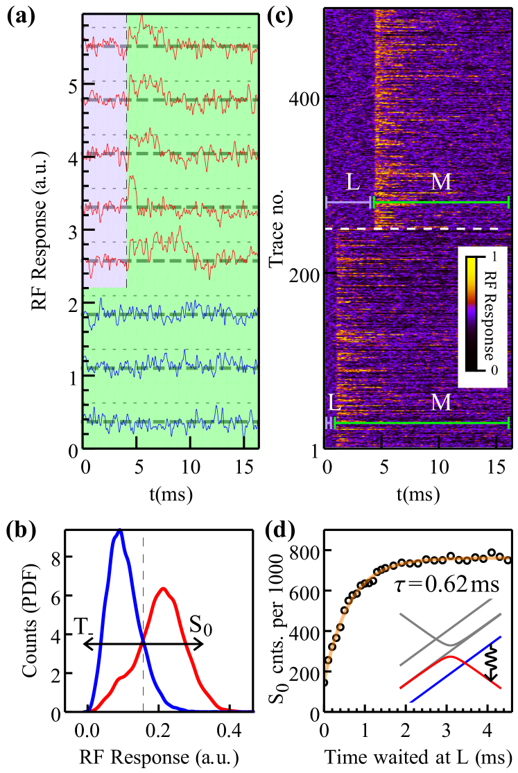
We perform single-shot measurements of spin-up electrons (equivalent to the singlet state) by waiting at point L for and then pulsing to point M at zero detuning for maximum RF response. Here we leave the RF tone switched on and measure the resulting response over time in Fig. 3a. Five such single-shot time-traces are shown in red demonstrating that we can detect a singlet state. Here, when moving to point M, the signal (dotted lines) clearly departs from the background level (dashed lines) and, after stochastic relaxation, returns back to the same level highlighting real-time single spin detection. The finite life-time of the non-zero signal can be attributed to the singlet-state decaying into the triplet ground state. To distinguish a singlet state from a triplet state, these traces were compared against traces (shown in blue) when waiting at point L (that is, always reading a triplet ) where the signal remains at the background level throughout the measurement. To quantify the fidelity of the single spin readout, we must discriminate between a fully null signal (triplet) and one with a non-zero signal (singlet). The singlet signal on average follows an exponential decay function (as shown in Fig. 2e). Therefore, the actual signal is concentrated around the beginning of the measurement and diminishes during the course of the measurement. Thus, we applied an exponential window over the portion of the signal where the measurement begins (after we have moved to zero detuning at point M) and then compiled a histogram of the maximum values of each trace D’Anjou and Coish (2014). The histogram shown in Fig. 3b was created from 10,000 traces taken after waiting at point L for and to measure the distribution for singlets and triplets respectively. We took a threshold (shown by the dotted line in Fig. 3b) to partition the distributions such that values above were considered to be singlet states and values below were considered to be triplet states. We determined that the optimal threshold to maximise the readout fidelity was 0.157 Elzerman et al. (2004); Gorman et al. (2017). This yielded an average single-spin readout fidelity, of the single-gate RF sensor, of (where the singlet and triplet readout fidelities were and respectively).
With the ability to perform single-shot, single-spin readout, we measure the to decay (at from zero detuning) by varying the time the pulse spends at point L. After every measurement, the electrons will have decayed into the triplet state. On initially pulsing to point L, the electrons (residing in separate dots) remain in instead of entering the charge state. This is because there is a slower tunnel rate of electrons from the reservoir R2 to D2U since it is further away when compared from R2 to D2L. Thus, the electrons cannot move to the charge state until the electron in D2L moves to D2U to enter the singlet state Yang et al. (2014); Pakkiam et al. (2018). Fig. 3c shows 250 traces taken when waiting at point L and 250 traces when waiting at point L. The RF response starts to appear when measuring at point M. The lengths of each non-zero signal are exponentially distributed with a time constant of and represent singlet states decaying into triplet states. When waiting a lower time at L, there is clearly a smaller proportion of singlet states. Fig. 3d shows the singlet-counts over 1000 traces taken at different wait times at point L. When viewing the singlet-counts as a function of the wait time at point L and fitting to the resulting exponential rise in the singlet counts, the decay time was measured to be . This corresponds to the upper bound in the measurement time when using a charge sensor to distinguish between and states Shulman et al. (2012).
IV Conclusion
In summary we demonstrated single shot readout of an electron spin using the singlet-triplet basis in silicon using a single-gate RF sensor. The reduction in gate density using a single-gate sensor simplifies architectures for large arrays of solid state qubits Veldhorst et al. (2017); Pakkiam et al. (2018). We demonstrated that the to relaxation time, which limits the qubit measurement time, was and unaffected by the presence of the RF tone. The single-gate RF sensor gave an average measurement fidelity of . The fidelity can be further improved by using resonators with higher internal quality factors along with better matching networks to the transmission line for greater signal strength. For example, in this experiment, if the internal and external quality factors were matched at 1600 the expected readout fidelity exceeds .
Acknowledgements
This research is supported by the Australian Research Council Centre of Excellence for Quantum Computation and Communication Technology (Project No. CE110001027) and the U.S. Army Research Office under Contract No. W911NF-17-1-0202. The device is fabricated in part at the New South Wales node of the Australian National Fabrication Facility. M.Y.S. acknowledges an Australian Research Council Laureate Fellowship.
References
- Veldhorst et al. (2017) M. Veldhorst, H. G. J. Eenink, C. H. Yang, and A. S. Dzurak, Nature Communications 8, 1766 (2017).
- Pakkiam et al. (2018) P. Pakkiam, M. G. House, M. Koch, and M. Y. Simmons, Nano Letters 18, 4081–4085 (2018).
- P. DiVincenzo and IBM (2000) D. P. DiVincenzo and IBM, Fortschritte der Physik, 48, 771 (2000).
- Loss and DiVincenzo (1998) D. Loss and D. P. DiVincenzo, Phys. Rev. A 57, 120–126 (1998).
- Levy (2002) J. Levy, Phys. Rev. Lett. 89, 147902 (2002).
- Hanson et al. (2007) R. Hanson, L. P. Kouwenhoven, J. R. Petta, S. Tarucha, and L. M. K. Vandersypen, Rev. Mod. Phys. 79, 1217–1265 (2007).
- Zwanenburg et al. (2013) F. A. Zwanenburg, A. S. Dzurak, A. Morello, M. Y. Simmons, L. C. L. Hollenberg, G. Klimeck, S. Rogge, S. N. Coppersmith, and M. A. Eriksson, Rev. Mod. Phys. 85, 961 (2013).
- Petta (2005) J. R. Petta, Science 309, 2180–2184 (2005).
- Shulman et al. (2012) M. D. Shulman, O. E. Dial, S. P. Harvey, H. Bluhm, V. Umansky, and A. Yacoby, Science 336, 202–205 (2012).
- Petersson et al. (2010) K. D. Petersson, C. G. Smith, D. Anderson, P. Atkinson, G. A. C. Jones, and D. A. Ritchie, Nano Letters 10, 2789 (2010), pMID: 20698590.
- Colless et al. (2013) J. I. Colless, A. C. Mahoney, J. M. Hornibrook, A. C. Doherty, H. Lu, A. C. Gossard, and D. J. Reilly, Phys. Rev. Lett. 110, 046805 (2013).
- House et al. (2015) M. G. House, T. Kobayashi, B. Weber, S. J. Hile, T. F. Watson, J. van der Heijden, S. Rogge, and M. Y. Simmons, Nature Communications 6, 8848 (2015).
- Fowler et al. (2012) A. G. Fowler, M. Mariantoni, J. M. Martinis, and A. N. Cleland, Phys. Rev. A 86, 032324 (2012).
- Weber et al. (2014) B. Weber, Y. H. M. Tan, S. Mahapatra, T. F. Watson, H. Ryu, R. Rahman, L. C. L. Hollenberg, G. Klimeck, and M. Y. Simmons, Nature Nanotechnology 9, 430–435 (2014).
- Broome et al. (2018) M. A. Broome, S. K. Gorman, M. G. House, S. J. Hile, J. G. Keizer, D. Keith, C. D. Hill, T. F. Watson, W. J. Baker, L. C. L. Hollenberg, and M. Y. Simmons, Nature Communications 9 (2018), 10.1038/s41467-018-02982-x.
- Watson et al. (2017) T. F. Watson, B. Weber, Y.-L. Hsueh, L. C. L. Hollenberg, R. Rahman, and M. Y. Simmons, Science Advances 3 (2017), 10.1126/sciadv.1602811.
- Colless and Reilly (2012) J. I. Colless and D. J. Reilly, Review of Scientific Instruments 83, 023902 (2012).
- Schaal et al. (2018) S. Schaal, S. Barraud, J. J. L. Morton, and M. F. Gonzalez-Zalba, Phys. Rev. Applied 9, 054016 (2018).
- Ahmed et al. (2018) I. Ahmed, J. A. Haigh, S. Schaal, S. Barraud, Y. Zhu, C.-m. Lee, M. Amado, J. W. A. Robinson, A. Rossi, J. J. L. Morton, and M. F. Gonzalez-Zalba, Phys. Rev. Applied 10, 014018 (2018).
- Fuechsle et al. (2012) M. Fuechsle, J. A. Miwa, S. Mahapatra, H. Ryu, S. Lee, O. Warschkow, L. C. L. Hollenberg, G. Klimeck, and M. Y. Simmons, Nature Nanotechnology 7, 242–246 (2012).
- Hornibrook et al. (2014) J. M. Hornibrook, J. I. Colless, A. C. Mahoney, X. G. Croot, S. Blanvillain, H. Lu, A. C. Gossard, and D. J. Reilly, Appl. Phys. Lett. 104, 103108 (2014).
- House et al. (2016) M. G. House, I. Bartlett, P. Pakkiam, M. Koch, E. Peretz, J. van der Heijden, T. Kobayashi, S. Rogge, and M. Y. Simmons, Phys. Rev. Applied 6, 044016 (2016).
- Gorman et al. (2018) S. K. Gorman, M. A. Broome, M. G. House, S. J. Hile, J. G. Keizer, D. Keith, T. F. Watson, W. J. Baker, and M. Y. Simmons, Applied Physics Letters 112, 243105 (2018).
- Weber et al. (2012) B. Weber, S. Mahapatra, H. Ryu, S. Lee, A. Fuhrer, T. C. G. Reusch, D. L. Thompson, W. C. T. Lee, G. Klimeck, L. C. L. Hollenberg, and M. Y. Simmons, Science 335, 64 (2012), http://science.sciencemag.org/content/335/6064/64.full.pdf .
- D’Anjou and Coish (2014) B. D’Anjou and W. A. Coish, Phys. Rev. A 89, 012313 (2014).
- Elzerman et al. (2004) J. M. Elzerman, R. Hanson, L. H. Willems van Beveren, B. Witkamp, L. M. K. Vandersypen, and L. P. Kouwenhoven, Nature 430, 431–435 (2004).
- Gorman et al. (2017) S. K. Gorman, Y. He, M. G. House, J. G. Keizer, D. Keith, L. Fricke, S. J. Hile, M. A. Broome, and M. Y. Simmons, Phys. Rev. Applied 8, 034019 (2017).
- Yang et al. (2014) C. H. Yang, A. Rossi, N. S. Lai, R. Leon, W. H. Lim, and A. S. Dzurak, Applied Physics Letters 105, 183505 (2014).