Manuscript Title:
Tailorable Twisting of Biomimetic Scale-Covered Substrate
Abstract
In this letter, we investigate the geometrically tailorable elasticity in the twisting behavior of biomimetic scale-covered slender soft substrate. Motivated by our qualitative experiments showing a significant torsional rigidity increase, we develop an analytical model and carry out extensive finite element (FE) simulations to validate our model. We discover a regime differentiated and reversible mechanical response straddling linear, nonlinear, and rigid behavior. The response is highly tailorable through the geometric arrangement and orientation of the scales. The work outlines analytical relationships between geometry, deformation modes and kinematics, which can be used for designing biomimetic scale-covered metamaterials.
Scales have been a recurring dermal feature in the evolutionary history of complex vertebrae Dou et al. (2012); Onozato and Watabe (1979); Chang et al. (2009); Di-Poï and Milinkovitch (2016); Chen et al. (2011); Wang et al. (2016); Bruet et al. (2008a). One of the reasons for their success is their tremendous multifunctional benefits, including hydrodynamic, chemical, and optical advantages Colbert et al. (1955); Sire et al. (2009); Vickaryous and Sire (2009); Willmer (1990). From a mechanical standpoint, scales traditionally provide protection against foreign objects and organism attacks Yang et al. (2013a); White and Vernerey (2018). This evolutionary requirement has made them structurally hybrid Ning et al. (2013); Rudykh et al. (2015); Drelich et al. (2018), hierarchical Fratzl and Weinkamer (2007); Lakes (1993); Qing and Mishnaevsky Jr (2009), and composite in nature Buehler (2006); Espinosa et al. (2011); Ortiz and Boyce (2008) capable of engaging multiple length scales Bruet et al. (2008b); Nelms et al. (2017); Song et al. (2011); Yang et al. (2013b); Browning et al. (2013); Zhu et al. (2013a, 2012, b). This feature has been an inspiration for recent work on using these principles for armor designs Wang et al. (2016); Yang et al. (2013a, b); Zimmermann et al. (2013). However, in addition to localized loads common in protective applications, another structural feature is of immense importance. That is the role of scale engagements in modifying the global deformation behavior of the underlying structure. This feature deepens the role of scales in aiding both locomotion Miller (1988) and swimming Long Jr and Nipper (1996); Raschi and Tabit (1992). The mechanics underscoring this behavior have been an area of intense scrutiny since the last few years. One-dimensional substrates with stiff scales revealed strain stiffening due to sliding, scale deformation as well as friction in the bending mode of deformation Vernerey and Barthelat (2010). Later simplification of the structure revealed the distinct nonlinear regimes of elasticity even without scale deformation or friction Ghosh et al. (2014). Nonlinearity due to frictional effects were further isolated and their effect on locking and dissipation quantified Ghosh et al. (2016). Further studies revealed the limits of theoretical assumptions underpinning the models and their effect on predicted relationships Ghosh et al. (2017); Ali et al. (2018). Extending the dimensionality of the problem, two-dimensional substrates were also investigated Funk et al. (2015); Martini et al. (2017); Vernerey and Barthelat (2014); Vernerey et al. (2014). These showed several similarities with their one-dimensional counterparts in bending. However, the mechanics of twisting, a critical and fundamental mode of global deformation has not yet been discussed in detail. Twisting mode of deformation is perceptible for some robotic applications Saab et al. (2018); Polygerinos et al. (2015); Roche et al. (2017); Ahn et al. (2012); YAMAFUJI et al. (1992); Jusufi et al. (2008, 2010) and can also arise due to boundary defects and bending-twisting coupling in structures Hassani et al. (2016); Antman (2005). Furthermore, this mode is an important first step towards more complex combined deformation modes and two-dimensional metamaterials of this type. In this letter, we study the response of stiff scale-covered slender biomimetic substrates under torsional loads and outline the gamut of geometrical tailorable of twisting elasticity.
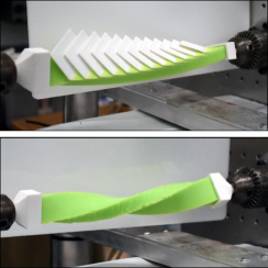
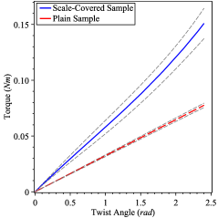
Twisting deformation of a uniform prismatic beam covered with scales and a plain sample is shown in Fig. 1a. We also carry on qualitative and motivational experiments on some real samples. For these samples, the scales were 3D printed and made of Poly Lactic Acid (PLA) thermoplastic. The substrate was made from a silicone elastomer known as Vinylpolysiloxane (VPS) by casting into a 3D printed mold. The mold was designed to leave grooves for scale insertions at the next stage. Then the scales were then embedded and adhered to these prefabricated grooves, a silicone glue (Permatex Corporate). Young’s modulus of PLA and VPS tested under tensile test by MTS Insight® (Electromechanical – Standard Length) were found to be and , respectively. We subjected the fabricated samples to twisting experiments in clockwise direction, contrasting their response using an MTS Bionix EM® (Electromechanical Torsion – ) with similar loading and boundary conditions. Note that the engagement happens only in the clockwise twist direction of the substrate. The twist rate was and the experiments have been done up to . The significant gains in torsional stiffness in the scale-covered samples were apparent when compared to a plain counterpart with same materials and geometry as shown in Fig. 1b. The uncertainties from different tests are shown as dashed lines up and down of each curves.
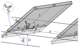
Using this motivating experiment, we investigate this twisting behavior by first developing a model for this system. Due to the high contrast in the elastic modulus between substrate and scale stiffness, we use a rigid scale assumption. We first simplify the geometry of this system, Fig. 2a. Each scale is considered a rectangular plate with thickness , width and total length , where is the length of the substrate embedded section and is the length of the exposed section. The patterned row of scales, spaced by and embedded on a rectangular prismatic substrate, is quantified in a general orientation defined with three angles , , and , Fig. 2b. Here, is the dihedral angle between the top surfaces of the substrate and the scale, is the angle between the substrate’s rectangular cross section and the edge of the scale’s width, and is the dihedral angle between the side surfaces of the substrate and the scale (the angle between normal unit vectors and of the side surfaces shown in Fig. 2b). We assume that the length of the beam and number of scales are large enough to satisfy the periodicity in the scale engagement under pure torsion with negligible edge effects. This allows the isolation of a representative volume element (RVE) formed one scale and the underlying substrate (scale’s thickness is neglected) at distance from adjacent scales embedded on the top surface of the beam, Fig. 2a.
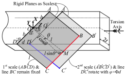
To develop the kinematics of the scale at the RVE level, consider the RVE scale (1st scale in Fig. 2a) fixed with respect to the one immediately preceding it (2nd scale in Fig. 2a). The second scale rotates about the torsion axis by twist angle of caused by the twisting of the underlying slender substrate, Fig. 2a. This leads to an RVE (local) twist rate . From Fig. 2a, if the second scale twists around the torsion axis, then engagement would only happen when one edge of rotated scale, , contacts at a point with the subsequent edge of the fixed scale. The continual twisting of the underlying beam progresses the contact between two consecutive scales, increasing the scale’s inclination angle from an initial angle to the current angle . This contact imposes kinematic constraints on scale sliding, leading to the following nonlinear relationship between the substrate’s twist angle and scale’s inclination angle (See Supplemental Material for derivation c (52)):
| (1) |
Where , , and are the overlap ratio, dimensionless scale width, and dimensionless substrate thickness, respectively. In the small twisting regime , the implicit constraint equation simplifies to the explicit . Furthermore for (thin substrate with grazing scales), we get . For higher range, i.e. , then for fixed and the first term will dominate and we will get . This is similar to the scaling law obtained from bending deformation Ghosh et al. (2014) and underscores the universal importance of scale overlap in amplifying global to local deformation. However, unlike bending, we also find an additional amplification factor underscoring the more general nature of this system.
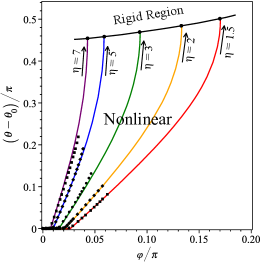
The governing nonlinear Eq. 1 establishes a phase map spanned by and , which is shown in Fig. 3a for different along with FE simulation results c (52). Here, , , , and . This phase diagram maps out three kinematic regimes of operations for the structure under twisting, which includes linear, nonlinear and rigid regions of operation. The linear region is a direct result of the non-engagement of scales. However, as soon as the scales begin engaging, a distinctly nonlinear regime emerges, tuned by . The angle of engagement decreases with increasing the overlap ratio. For relatively smaller deformation, an explicit relationship emerges between and other kinematic parameters, . The stiffening increases with scale sliding, ultimately leading to a point where no more sliding is possible without significantly deforming the scales themselves. This is the third regime of deformation, called ”locking”. At this point, the system begins to behave almost as a rigid body, completing the regime traversal. We find this rigidity envelope mathematically by satisfying , which forms the defining envelope of operation. Locking signals a sharp rise in contact forces, which violates the scale rigidity condition near the envelope due to local scale deformation. Around that phase boundary, the stiffness of the whole system transitions towards the stiffness of the scales, which are significantly stiffer than the substrate. This is consistent with previously published work on this topic Ghosh et al. (2014); Vernerey and Barthelat (2014).
Also, if is sufficiently small, no engagement is possible and this is the geometrical limit of engagement. This computes to and is physically meaningful if c (52). The agreement of the analytical relationship with FE simulations in Fig. 3a shows minimal effect of substrate warping on the kinematics.
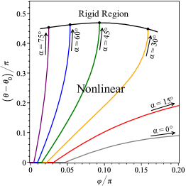
We explore this geometric tailorability of elasticity in greater detail using another phase map, parametrized by , Fig. 3b with , , , and . This phase map shows that increasing not only leads to a quicker engagement but also steeper nonlinearity. This also shows that there exists a critical , below which no locking would be possible for a given set of geometrical parameters. Also note that, although increasing always leads to decreasing locking twist angle, this trend does not hold for .
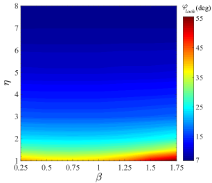
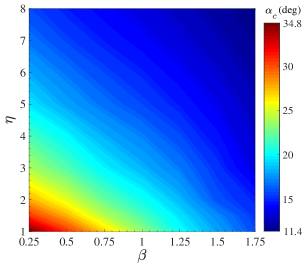
These effects are summarized using two other phase diagrams, both spanned by and in Fig. 4a and Fig. 4b. Fig. 4a indicates that locking angles decrease for higher . Further, higher depresses the sensitivity of locking angle to . However, the locking angle sharply increases with for low enough . Therefore, only in the lower overlap ratios, becomes an important tuning parameter of the locking behavior. Interestingly, this phase plot shows that although higher always decreases the envelope of operation, the influence of is strongly dependent on . In Fig. 4b, which tracks the critical angle below which locking would not take place, similar tuning behavior of is apparent. However, in this case, as increases the locking possibility improves. Note that, in these phase plots .
These kinematic nonlinearities ensure that mechanical response would also be nonlinear even when the materials themselves are in the linear elastic regime. We consider the twisting of the biomimetic scale-covered substrate as a combination of plain beam twisting and scales rotation. The scale rotation in 3D space can be defined by change in angles , , and , introduced earlier, Fig. 2b. As the scales engage and begin rotating, the elastic substrate resists scales rotation. The substrate resistance is modeled as linear torsional springs corresponding to the change in each of the angles , , and . Thus the energy absorbed due to the 3D rotation of each scale can be described as , where , , and are the corresponding rotational spring constants. Extensive FE simulations indicate that the contributions from both and terms are negligible c (52). This leads to . The most significant variables for determining the scale-substrate joint stiffness is the Young’s Modulus of substrate , the embedded length of scales , width of the scale , the thickness of the scale as well as and . We further assume that and . Considering this system as a single scale embedded in a semi-infinite beam in length and thickness, we postulate the following scaling expression:
| (2) |
where is a dimensionless constant, and and are dimensionless angular functions. We carried out FE simulations on a single scale embedded in a semi-infinite media and varied the relevant geometric variables of Eq. 2 to ascertain the fit of this empirical relationship. We find an excellent fit in the region of , yielding , , and , indicating negligible angular dependence c (52).
In non-circular cross sections, warping leads to an out-of-plane displacement even in small deformation Connor (1976). Although warping’s effect of kinematics was negligible, its effect on mechanics must be accounted. Typically, the effect of warping is addressed using a non-dimensional pre-multiplier in the relationship between torque and twist rate leading to , where is the RVE (local) torque, is the shear modulus of elasticity, and is the moment of area of the beam cross section, respectively. can be found from literature for standard cross sections Ugural and Fenster (2011). In addition, the embedding of rigid inclusions leads to an increase in stiffness even before engagement and is modeled using an inclusion correction factor , which would depend on the volume fraction, shape and size of the inclusion. This leads to a modified torque-twist relationship . Motivated by elasticity arguments, we postulate that , where , and are dimensionless angular functions to describe the dependence of to and . We ascertained the fit, using FE numerical simulations c (52), yielding , , and , indicating negligible angular dependence. With these assumptions, work-energy balance for the unit length of the substrate can be described as:
| (3) |
where is the Heaviside step function to track scales engagement. The right-hand side of this equation can be considered as the summation of the energy absorbed by the substrate’s elastic torsion , and the scales engagement . The torque-twisting rate relationship for the system could be found by differentiating Eq. 3 with respect to and is written as:
| (4) |
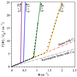
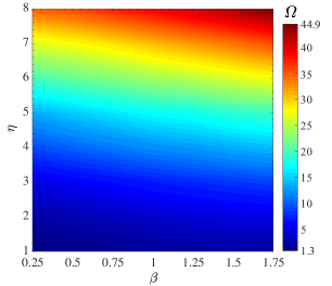
This nonlinear expression is plotted in Fig. 5a for different with , , , and . The properties of the substrate are considered as and with the cross section’s dimension of . The scale spacing, the thickness and the embedded length of the scales are assumed as , and . The results are compared to analogous FE simulations and we find a remarkably good fit with our model. The plot clearly demonstrates the sharp rise in nonlinear stiffening. The plot also highlights the inclusion effect in significantly increasing the torsional stiffness even before the engagement and underscores the accuracy of our model. We quantify the geometric tailorability of elastic energy of this system by using a magnification factor , which is the ratio of maximum possible energy absorbed by a substrate (from initial to lock) to an equivalent plain substrate. This factor is plotted in a phase map spanned by and , Fig. 5b, and shows the rapid increase of energy brought about by for any given . However for a given the increase is relatively mild but still monotonic positive (see Table SI in c (52)). This establishes the role of these parameters in both boosting stiffness and increasing energy, even though increasing leads to lower envelope of operation.
The linearized torque-twist for small is:
| (5) |
where we recall that . This linearized analytical expression sheds important light on the role of geometric parameters in enhancing the torsional stiffness of the substrate in small deformation. Particularly apparent is the effect of the lateral parameter, which has a nearly cubic relationship to torque. Therefore, increasing the width of the scales quickly increases rotational stiffness, significantly decreasing compliance in twisting. The effect of overlap ratio is quadratic, similar to bending behavior. This highlights the distinctness of the twisting response of the biomimetic scale-covered substrate. This plot also conforms with the more gentle slope of the experimental sample which corresponds to are , , , , and , which leads to , , . (see Fig. S5 in c (52))
In conclusion, our work shows the geometrical tailorability of elastic response under twisting loads including stiffness, envelopes of operations and the overall energy landscape. We find that stiffness increase brought about by scales is highly nonlinear, reversible, rapid and tailorable, distinct from simply coating or embedding with a stiffer material or making a composite. This system exhibits a very specific nonlinear behavior which includes a seamless straddling between linear elastic, nonlinear elastic and finally a quasi-rigid behavior which exhibited by neither the PLA nor the silicone material. Each one of these regimes can be tailored using a different geometrical arrangement. This study strengthens the arguments of using biomimetic scales for designing structural metamaterials in a wide range of applications beyond simple bending. The current analytical model is aimed primarily to obviate the need for detailed fully resolved FE simulations for some aspects of design and analysis. These FE simulations become prohibitive for larger number of scale contacts, larger twists or for future work on dynamics, which would require repeated FE simulations on the structure.
References
- Dou et al. (2012) Z. Dou, J. Wang, and D. Chen, Journal of bionic Engineering 9, 457 (2012).
- Onozato and Watabe (1979) H. Onozato and N. Watabe, Cell and tissue research 201, 409 (1979).
- Chang et al. (2009) C. Chang, P. Wu, R. E. Baker, P. K. Maini, L. Alibardi, and C.-M. Chuong, The International journal of developmental biology 53, 813 (2009).
- Di-Poï and Milinkovitch (2016) N. Di-Poï and M. C. Milinkovitch, Science advances 2, e1600708 (2016).
- Chen et al. (2011) I. H. Chen, J. H. Kiang, V. Correa, M. I. Lopez, P.-Y. Chen, J. McKittrick, and M. A. Meyers, Journal of the mechanical behavior of biomedical materials 4, 713 (2011).
- Wang et al. (2016) B. Wang, W. Yang, V. R. Sherman, and M. A. Meyers, Acta biomaterialia 41, 60 (2016).
- Bruet et al. (2008a) B. J. Bruet, J. Song, M. C. Boyce, and C. Ortiz, Nature materials 7, 748 (2008a).
- Colbert et al. (1955) E. H. Colbert et al., Evolution of the vertebrates. A history of the backboned animals through time. (1955).
- Sire et al. (2009) J.-Y. Sire, P. C. Donoghue, and M. K. Vickaryous, Journal of Anatomy 214, 409 (2009).
- Vickaryous and Sire (2009) M. K. Vickaryous and J.-Y. Sire, Journal of Anatomy 214, 441 (2009).
- Willmer (1990) P. Willmer, Invertebrate relationships: patterns in animal evolution (Cambridge University Press, 1990).
- Yang et al. (2013a) W. Yang, I. H. Chen, B. Gludovatz, E. A. Zimmermann, R. O. Ritchie, and M. A. Meyers, Advanced Materials 25, 31 (2013a).
- White and Vernerey (2018) Z. W. White and F. J. Vernerey, Bioinspiration & biomimetics 13, 041004 (2018).
- Ning et al. (2013) G. Ning, T. Li, J. Yan, C. Xu, T. Wei, and Z. Fan, Carbon 54, 241 (2013).
- Rudykh et al. (2015) S. Rudykh, C. Ortiz, and M. C. Boyce, Soft Matter 11, 2547 (2015).
- Drelich et al. (2018) A. J. Drelich, S. N. Monteiro, J. Brookins, and J. W. Drelich, Advanced Biosystems 2, 1800055 (2018).
- Fratzl and Weinkamer (2007) P. Fratzl and R. Weinkamer, Progress in Materials Science 52, 1263 (2007).
- Lakes (1993) R. Lakes, Nature 361, 511 (1993).
- Qing and Mishnaevsky Jr (2009) H. Qing and L. Mishnaevsky Jr, Mechanics of Materials 41, 1034 (2009).
- Buehler (2006) M. J. Buehler, Proceedings of the National Academy of Sciences 103, 12285 (2006).
- Espinosa et al. (2011) H. D. Espinosa, A. L. Juster, F. J. Latourte, O. Y. Loh, D. Gregoire, and P. D. Zavattieri, Nature communications 2, 173 (2011).
- Ortiz and Boyce (2008) C. Ortiz and M. C. Boyce, Science 319, 1053 (2008).
- Bruet et al. (2008b) B. J. Bruet, J. Song, M. C. Boyce, and C. Ortiz, Nature materials 7, 748 (2008b).
- Nelms et al. (2017) M. Nelms, W. Hodo, and A. Rajendran, Journal of the mechanical behavior of biomedical materials 69, 395 (2017).
- Song et al. (2011) J. Song, C. Ortiz, and M. C. Boyce, Journal of the mechanical behavior of biomedical materials 4, 699 (2011).
- Yang et al. (2013b) W. Yang, B. Gludovatz, E. A. Zimmermann, H. A. Bale, R. O. Ritchie, and M. A. Meyers, Acta biomaterialia 9, 5876 (2013b).
- Browning et al. (2013) A. Browning, C. Ortiz, and M. C. Boyce, Journal of the mechanical behavior of biomedical materials 19, 75 (2013).
- Zhu et al. (2013a) D. Zhu, F. Barthelat, and F. Vernerey, MICROMECHANICS (2013a).
- Zhu et al. (2012) D. Zhu, C. F. Ortega, R. Motamedi, L. Szewciw, F. Vernerey, and F. Barthelat, Advanced Engineering Materials 14, B185 (2012).
- Zhu et al. (2013b) D. Zhu, L. Szewciw, F. Vernerey, and F. Barthelat, Journal of the mechanical behavior of biomedical materials 24, 30 (2013b).
- Zimmermann et al. (2013) E. A. Zimmermann, B. Gludovatz, E. Schaible, N. K. Dave, W. Yang, M. A. Meyers, and R. O. Ritchie, Nature communications 4, 2634 (2013).
- Miller (1988) G. S. Miller, ACM Siggraph Computer Graphics 22, 169 (1988).
- Long Jr and Nipper (1996) J. H. Long Jr and K. S. Nipper, American Zoologist 36, 678 (1996).
- Raschi and Tabit (1992) W. Raschi and C. Tabit, Marine and Freshwater Research 43, 123 (1992).
- Vernerey and Barthelat (2010) F. J. Vernerey and F. Barthelat, International Journal of Solids and Structures 47, 2268 (2010).
- Ghosh et al. (2014) R. Ghosh, H. Ebrahimi, and A. Vaziri, Applied Physics Letters 105, 233701 (2014).
- Ghosh et al. (2016) R. Ghosh, H. Ebrahimi, and A. Vaziri, EPL (Europhysics Letters) 113, 34003 (2016).
- Ghosh et al. (2017) R. Ghosh, H. Ebrahimi, and A. Vaziri, Journal of the mechanical behavior of biomedical materials 72, 1 (2017).
- Ali et al. (2018) H. Ali, H. Ebrahimi, and R. Ghosh, arXiv preprint arXiv:1807.00066 (2018).
- Funk et al. (2015) N. Funk, M. Vera, L. J. Szewciw, F. Barthelat, M. P. Stoykovich, and F. J. Vernerey, ACS applied materials & interfaces 7, 5972 (2015).
- Martini et al. (2017) R. Martini, Y. Balit, and F. Barthelat, Acta biomaterialia 55, 360 (2017).
- Vernerey and Barthelat (2014) F. J. Vernerey and F. Barthelat, Journal of the Mechanics and Physics of Solids 68, 66 (2014).
- Vernerey et al. (2014) F. J. Vernerey, K. Musiket, and F. Barthelat, International Journal of Solids and Structures 51, 274 (2014).
- Saab et al. (2018) W. Saab, W. S. Rone, and P. Ben-Tzvi, Robotica , 1 (2018).
- Polygerinos et al. (2015) P. Polygerinos, Z. Wang, K. C. Galloway, R. J. Wood, and C. J. Walsh, Robotics and Autonomous Systems 73, 135 (2015).
- Roche et al. (2017) E. T. Roche, M. A. Horvath, I. Wamala, A. Alazmani, S.-E. Song, W. Whyte, Z. Machaidze, C. J. Payne, J. C. Weaver, G. Fishbein, et al., Science Translational Medicine 9, eaaf3925 (2017).
- Ahn et al. (2012) S.-H. Ahn, K.-T. Lee, H.-J. Kim, R. Wu, J.-S. Kim, and S.-H. Song, International Journal of Precision Engineering and Manufacturing 13, 631 (2012).
- YAMAFUJI et al. (1992) K. YAMAFUJI, T. KOBAYASHI, and T. KAWAMURA, Journal of the Robotics Society of Japan 10, 648 (1992).
- Jusufi et al. (2008) A. Jusufi, D. I. Goldman, S. Revzen, and R. J. Full, Proceedings of the National Academy of Sciences 105, 4215 (2008).
- Jusufi et al. (2010) A. Jusufi, D. Kawano, T. Libby, and R. J. Full, Bioinspiration & biomimetics 5, 045001 (2010).
- Hassani et al. (2016) M. Hassani, N. W. Mureithi, and F. P. Gosselin, Journal of Fluids and Structures 62, 367 (2016).
- Antman (2005) S. S. Antman, “Problems in nonlinear elasticity,” in Nonlinear Problems of Elasticity (Springer, 2005) Chap. 14, pp. 513–584.
- c (52) See Supplemental Material at https://journals.aps.org/prapplied/ for derivation.
- Connor (1976) J. J. Connor, “St. venant theory of torsion-flexure of prismatic members,” in Analysis of Structural Member Systems (Ronald Press Co., 1976) Chap. 11, pp. 271–329.
- Ugural and Fenster (2011) A. C. Ugural and S. K. Fenster, “Torsion of prismatic bars,” in Advanced Mechanics of Materials and Applied Elasticity (Pearson Education, 2011) Chap. 6, pp. 292–336.