How super-tough gels break
Abstract
Fracture of highly stretched materials challenges our view of how things break. We directly visualize rupture of tough double-network (DN) gels at >50% strain. During fracture, crack tip shapes obey a power-law, in contrast to the parabolic profile observed in low-strain cracks. A new length-scale emerges from the power-law; we show that scales directly with the stored elastic energy, and diverges when the crack velocity approaches the shear wave speed. Our results show that DN gels undergo brittle fracture, and provide a testing ground for large-strain fracture mechanics.
Gels and rubbers are soft materials that are often tough to break Creton and Ciccotti (2016); Ducrot et al. (2014); Filippidi et al. (2017). Fracture in these materials typically occurs at strains exceeding 10%. In contrast, our common understanding of how things break, Linear Elastic Fracture Mechanics (LEFM) Griffith (1922); Irwin (1957); Eshelby (1971); Freund (1998), is a small strain theory. LEFM predicts that under applied tension, stresses at a distance from a crack’s tip diverge as , leading to a parabolic crack opening. Knowing the stress distribution allows one to calculate the energy flux into a crack’s tip, , which must balance the energetic cost of fracture . Energy balance results in an equation of motion for cracks that predicts that crack velocities are limited by the Rayleigh wave speed . Previous studies have shown that these predictions remain valid under moderate applied strains Goldman-Boué et al. (2015). How fracture mechanics change for cracks propagating under large strains, where strongly nonlinear effects appear, is an unresolved question.
Tough hydrogels are a novel arena for testing theories for large strain fracture Webber et al. (2007); Nakajima et al. (2013); Mayumi et al. (2016); Sun et al. (2012). Hydrogels are aqueous solids that owe their rigidity to a sparse network of cross-linked polymer chains Tanaka (1981). Their resemblance and compatibility with biological tissues make hydrogels natural candidates for biomedical applications Lee and Mooney (2001); Haque et al. (2012). However, the low fracture toughness of common gels Chen et al. (2017); Zhao (2017) is a major limit to their performance. By increasing the complexity of gel structure such limits may be pushed much further than previously thought Tanaka et al. (2005); Wu et al. (2017). In a double-network (DN) gel, following the polymerization of a first brittle network, the gel is immersed in a bath of a second monomer which is then polymerized to make a loosely cross-linked second network Gong et al. (2003). The fracture energies of these materials are orders of magnitude higher than either of the individual networks on their own Yu et al. (2009). The origin of these remarkable properties lies in the ability of the material to dissipate a large portion of the mechanical work through dissociation of sacrificial bonds in the first (stiff) network, while the second (soft) network keeps the medium intact Ahmed et al. (2014).
Here we study the dynamic fracture of covalently cross-linked DN gels by directly visualizing how they fracture in real time. We observe the propagation of brittle cracks whose opening follows a power-law that deviates from the parabolic shape predicted by LEFM. In analogy to LEFM, we define a length-scale from the crack tip opening and show that it grows with the elastic energy stored in the sample prior to crack propagation. Hence, whereas dynamic cracks in DN gels do not strictly abide by LEFM, they bear striking similarities to cracks in brittle elastic materials.
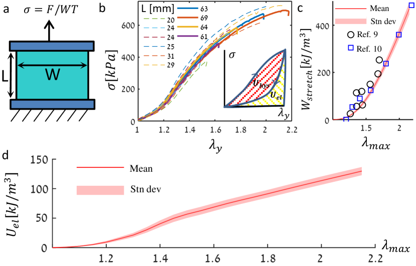
Our experiments were conducted using DN hydrogels prepared according to the following protocol Gong et al. (2003); Ahmed et al. (2014). The first network was polymerized from a 1M solution of 2-acrylamido-2-methylpropane sulfonic acid sodium salt (NaAMPS) with 4mol% N,N’-Methylenebisacrylamide (MBAA) as the cross-linker and 1mol% -ketoglutaric (-keto) acid as the initiator. The second network was polymerized from a 2M solution of acrylamide with 0.01mol% MBAA and 0.01mol% -keto. The gels were prepared in a reaction cell consisting of two glass plates separated by a silicone spacer. Fully water-swollen gel sheets, of thickness mm, were cut into a rectangular shape, of width mm along the (propagation) dimension. We employed samples of both large (mm) and small (mm) aspect ratios in the loading () direction. Prior to each experiment, spray paint was applied to one face of the gel sheet to create a dense pattern for further processing by means of Digital Image Correlation (DIC) Blaber et al. (2015). Instantaneous displacements and strains applied to “virgin” (previously un-stretched) gel samples were thus determined during both the loading cycle and the fracture experiments in this manner. The gel sheets were placed into a custom, self-tightening gripping mechanism, and loaded in tension along the -axis by a translation stage with a loading rate of 1 mm/sec, as depicted in Fig. 1(a). The applied load was monitored at 100 Hz by an amplified load cell signal. To determine the instantaneous state of stretch, images of the gel sheet were taken at 3 frames per second during the loading.
Dynamic fracture occurs when the energy flux into the crack tip, , is equal to the fracture energy, (the energy dissipated per unit crack length). Do DN gels behave as elastic media during dynamic fracture? To answer this question, we first determine the amount of elastic energy stored in the sample prior to fracture via the stress-stretch relation during the loading stage. Fig. 1(b) presents the nominal stress as a function of the applied stretch , measured in-situ using DIC when each sample was stretched for the first time. The stress-stretch behavior of the material is reproducible and independent of sample size, as shown for 10 samples. Fig. 1(c) depicts the total work per unit volume , computed by averaging over our data and integrating the areas under the average curve . The resulting values agree with previous studies Webber et al. (2007); Nakajima et al. (2013). During the loading stage, a significant part of the stretching work is dissipated through dissociation of sacrificial bonds (see inset of Fig. 1(b)), which we denote by . We estimate the remaining elastic energy per unit volume , presented in Fig. 1(d), by using previously published values of the relative hysteretic loss (50%-70% for the stretches considered here). Interestingly, in the few minutes between the cessation of loading and crack initiation, the stress in the sample relaxed by a few percent, with no associated material displacement, resulting hook-shaped endings of the curves in Fig. 1 (b). This relaxation indicates that material damage is at least partially rate dependent Yu et al. (2009).
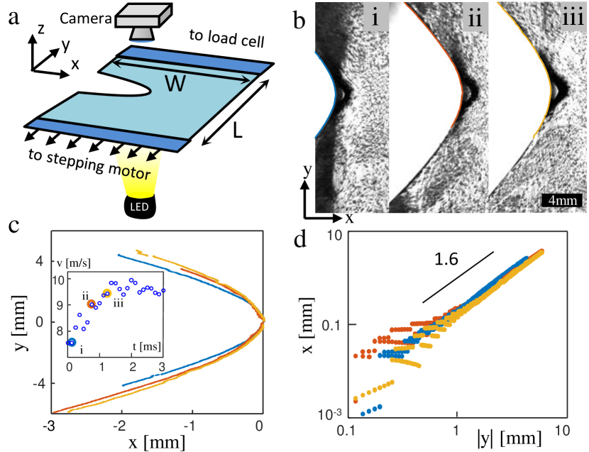
Upon the cessation of loading, we used a razor blade to introduce a small notch into the edge of the pre-stressed sample along its centerline (). At a critical notch length, rapid crack propagation immediately ensued. Crack dynamics were recorded by a 2 megapixel high-speed camera at 8000 frames per second, in a window of mm (in the laboratory frame) surrounding the center of the sample with a typical resolution of 20 m per pixel. The transparent gels were illuminated (see Fig.2(a)) by a 2 sec-pulsed, spatially uniform and monochromatic LED light source.
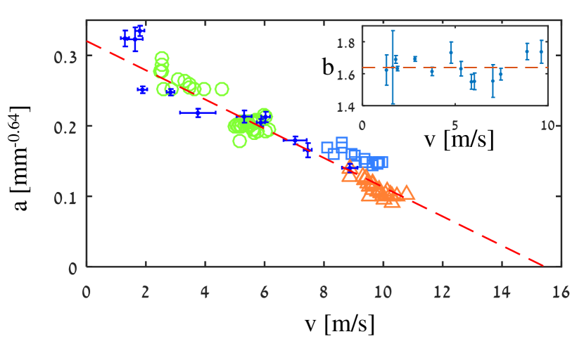
The crack tip opening displacement (CTOD) provides a window into the material properties at the extreme strains for which fracture occurs. Our real-time imaging of propagating cracks allows us to directly study the CTOD Goldman et al. (2010) and its dependence on loading conditions and crack velocities, . Extracting the CTOD from each image (Fig. 2(b,c)) reveals that cracks in DN gels deviate significantly from the LEFM-predicted parabolic profile Irwin (1957). Instead, the crack shape follows a power-law (Fig. 2(d)). For a given velocity, we find no significant difference in the CTODs measured for accelerating cracks and cracks propagating at a steady velocity, suggesting that these cracks have no inertia Goldman et al. (2010). Fitting the power-law function to CTODs at steady velocities, we find that does not depend on velocity, as shown in Fig. 2(c,d) and Fig. 3; averaging over >240 CTODs yields , where the error is the standard deviation. We fix and extract the pre-factor, , as a function of (Fig. 3). decreases approximately linearly with , indicating a systematically increasing CTOD with . A linear regression intersects the velocity axis at m/s; this would correspond to a completely open crack (zero curvature) profile.
The nontrivial power law description of the CTOD defines a new dynamic length scale, . The measured range corresponds to mm. In LEFM, the length scale defined by the CTOD, the radius of curvature, is proportional to where is the shear modulus. By analogy, we seek to determine whether is similarly related to the dissipation at the crack tip, or arises from another physical mechanism. Relating to requires the determination of the high-rate shear modulus that is defined within the stretched (and damaged) state of the material.
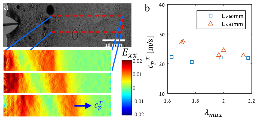
Fortunately, it is possible to directly measure the elastic response to a perturbation in-situ, immediately prior to fracture. At the initial stages of crack propagation, a longitudinal elastic wave is emitted from the accelerating crack tip. This wave perturbs the strain field as it propagates along the direction, spanning the sample’s breadth. Via DIC, we computed the instantaneous local strain . Three sequential snapshots of typical strain fields formed by a wave propagating along the -axis are presented in Fig. 4 (a). Averaging along the -axis to reduce noise, we find that the pulse-like disturbance propagates at a constant speed , corresponding to the plane stress longitudinal wave velocity along the -axis in the lab frame. This measurement provides the value of at precisely the damaged and stretched conditions for which fracture takes place. Fig. 4 (b) depicts the variation of with the background stretch and sample geometry . m/s is nearly constant for the large aspect ratio samples, while it is slightly larger and decreases with stretch in the small aspect ratio samples.
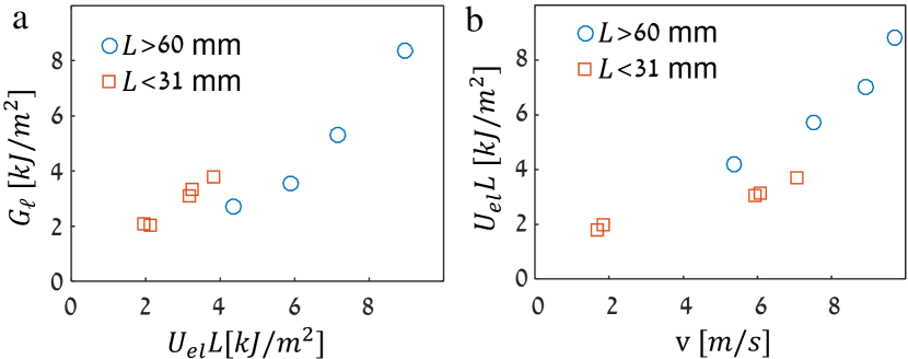
Is the length scale related to the dissipation inherent in fracture? We examine this question by studying the CTODs of cracks at steady velocities. When dissipation is confined to a microscopic zone surrounding the crack tip, cracks consume a fixed amount of elastic energy per unit area . In a small aspect ratio sample in uniform tension, G approximately equals the constant elastic energy stored per unit crack extension, Goldman et al. (2010), and the crack is said to be under “infinite strip” conditions. In a finite sample, the infinite strip approximation is valid seconds after fracture initiation, where is the shear wave speed along the -axis Marder (1991); Petersan et al. (2004). By analogy with LEFM, we construct an energetic measure from the CTOD length-scale . Here, the plane stress shear modulus is she ; Landau and Lifshitz (1970), and g/cm3 the gel density. kPa calculated from values in Fig. 4(b) agrees with the small-strain modulus of the virgin samples (Supplementary Fig. 1) sup .
Plotting at steady velocities against we observe (Fig. 5(a)) that these energetic measures are nearly equal over a wide range of experimental conditions. A closer examination shows that while for small aspect ratio samples (), for aspect ratio samples. This difference might arise since the samples are “strips” only to a first approximation; in these samples the stored elastic energy is not fully dissipated in fracture.
Brittle fracture occurs when inertia dominates dissipation and a crack, once formed, will continuously accelerate to acoustic speeds by releasing the elastic energy stored in the surrounding material. This contrasts with ductile fracture where crack propagation instantaneously mirrors external loads. Our results show that covalently cross-linked DN gels fail via brittle fracture. As Fig. 5(a) shows, is proportional to the elastic energy released in fracture. Thus, plays a role analogous to the radius of curvature in parabolic LEFM CTODs. This correspondence indicates that the crack shape and the energy flux into the crack tip are mainly determined by elastic stresses in the material. Further support for this claim comes from Fig. 3 where the CTOD prefactor extrapolates to zero as m/s exactly like the crack tip curvature of LEFM cracks as Freund (1998); Livne et al. (2008); Bouchbinder et al. (2008). For our incompressible gels, in plane stress, we estimate m/s Landau and Lifshitz (1970), which is in the range of the extrapolated zero-crossing of . Hence, we see that dynamic cracks in DN gels are similarly limited by acoustic speeds.
It is surprising that DN gels undergo brittle fracture while having very high . Typical values for hydrogels, J/m2, are explained by the Lake-Thomas mechanism where polymer chains bridging the crack faces snap when stretched to their maximum length. Since for DN gels, J/m2 Tanaka et al. (2005) (Fig. 5(b)) there must be an additional dissipative mechanism. In quasi-static tearing experiments Yu et al. (2009), the crack tip is surrounded by a ‘damage zone’, whose mm size explains this substantial increase in fracture energy. The propagation of dynamic brittle cracks is only possible if dissipation is confined to a small region near the crack tip. Outside of this region, material response must be virtually elastic. To gage whether a damage zone is present in our experiment, we measured the residual strains adjacent to a crack face in a fractured gel. A crack with mm, and kJ/m2 left behind a mm wide wake of % residual strains (see Supplementary Fig. 2)sup . Beyond residual strains are negligible. Wake formation may also be evident in the highly deformed bubble-like feature immediately ahead of the crack tips in Fig. 2(b). The clear separation of length scales therefore explains the brittle fracture observed in our experiments.
What happens if a crack is introduced into a rectangular DN gel sheet prior to stretching? At a constant loading rate, fracture initially progresses in a ductile manner (i.e. concomitantly with the loading) Ahmed et al. (2014). Preliminary results show, however, that at a certain length, the crack becomes unstable and rapid fracture ensues. Further study is necessary to elucidate the transition between the two regimes.
Given that material deformation surrounding dynamic cracks in DN gels is mostly elastic, why do CTODs have a 1.6 power-law? Non-parabolic CTODs of the form appear when the elastic energy density at large strains scales as , where is the first strain invariant Geubelle and Knauss (1994); Long et al. (2011). A simple scaling argument shows that which results in for sup . When the material stiffness increases with stretch. In rubbers, stiffening is observed due to the finite extensibility of polymer chains. To test the effect of rubber stiffening with strain on the CTOD, we solved for the deformation of a nonlinearly elastic Arruda-Boyce material Boyce and Arruda (2000) surrounding a static crack using finite-elements and observed CTODs with . In DN gels, nonlinear elastic response is observed when they are loaded for a second time. The stress-strain curve in a previously stretched sample, empirically, becomes increasingly steeper when approaching the previous maximal . Thus, nonlinear elastic stiffening at large strains may lead to the observed non-parabolic CTODs with . Future work may probe how nonlinear elastic stiffening affects the CTOD exponent by modifying the gel network structure Tanaka et al. (2005); Ahmed et al. (2014).
While we expect that network stiffening with increasing strain will explain the power , the CTOD should be also affected by the elastic anisotropy of the damaged gel. Our in-situ determination of reveals that is near the shear modulus of the undamaged material. It is therefore conceivable that while the first tensile loading changes the elasticity along the stretch axis drastically, it preserves the elasticity of the virgin material perpendicular to the stretch axis. This conclusion is consistent with observed anisotropic microscopic structure of damaged gels Tominaga et al. (2007).
We have shown that brittle dynamic fracture ensues in pre-stretched DN gels at strains greater than 50%. The crack tip profiles follow a nontrivial power-law that is characterized by a length that scales with the stored elastic energy divided by the shear modulus. We envision that our observations of the CTOD are closely linked to elastic properties of the gel, which are determined by complex and often hidden internal processes within the material. These macroscopic observations therefore provide a new window into the microscopic structure of the gel network under the extreme conditions that characterize fracture. We therefore believe that these results have the potential to both significantly improve our understanding of the origin of toughness in DN gels and pave the way for future theories of large strain fracture.
Acknowledgments: J. F. and I. K. acknowledge the support of the Israel Science Foundation (Grant No. 1523/15), as well as the US-Israel Bi-national Science Foundation (Grant No. 2016950). J.M.K. acknowledges the Fulbright-Israel post-doctoral fellowship. J. P. G. acknowledges the support of ImPACT Program of Council for Science, Technology and Innovation (Cabinet Office, Government of Japan).
References
- Creton and Ciccotti (2016) C. Creton and M. Ciccotti, Reports on Progress in Physics 79, 046601 (2016).
- Ducrot et al. (2014) E. Ducrot, Y. Chen, M. Bulters, R. P. Sijbesma, and C. Creton, Science 344, 186 (2014).
- Filippidi et al. (2017) E. Filippidi, T. R. Cristiani, C. D. Eisenbach, J. H. Waite, J. N. Israelachvili, B. K. Ahn, and M. T. Valentine, Science 358, 502 (2017).
- Griffith (1922) A. A. Griffith, Phil. Trans. R. Soc. Lond. A 222, 163 (1922).
- Irwin (1957) G. R. Irwin, J. Appl. Mech. 24, 361 (1957).
- Eshelby (1971) J. D. Eshelby, Sci. Prog. 59, 161 (1971).
- Freund (1998) L. B. Freund, Dynamic fracture mechanics (Cambridge university press, 1998).
- Goldman-Boué et al. (2015) T. Goldman-Boué, R. Harpaz, J. Fineberg, and E. Bouchbinder, Soft Matter 11, 3812 (2015).
- Webber et al. (2007) R. E. Webber, C. Creton, H. R. Brown, and J. P. Gong, Macromolecules 40, 2919 (2007).
- Nakajima et al. (2013) T. Nakajima, T. Kurokawa, S. Ahmed, W. Wu, and J. P. Gong, Soft Matter 9, 1955 (2013).
- Mayumi et al. (2016) K. Mayumi, J. Guo, T. Narita, C. Y. Hui, and C. Creton, Extreme Mech. Lett. 6, 52 (2016).
- Sun et al. (2012) J. Y. Sun, X. Zhao, W. R. K. Illeperuma, O. Chaudhuri, K. H. Oh, D. J. Mooney, J. J. Vlassak, and Z. Suo, Nature 489, 133 (2012).
- Tanaka (1981) T. Tanaka, Sci. Am. 244, 124 (1981).
- Lee and Mooney (2001) K. Y. Lee and D. J. Mooney, Chem. Rev. 101, 1869 (2001).
- Haque et al. (2012) M. A. Haque, T. Kurokawa, and J. P. Gong, Polymer 53, 1805 (2012).
- Chen et al. (2017) C. Chen, Z. Wang, and Z. Suo, Extreme Mech. Lett. 10, 50 (2017).
- Zhao (2017) X. Zhao, Proc. Nat. Ac. Sci. 114, 8138 (2017).
- Tanaka et al. (2005) Y. Tanaka, R. Kuwabara, Y. H. Na, T. Kurokawa, J. P. Gong, and Y. Osada, J. Phys. Chem. B 109, 11559 (2005).
- Wu et al. (2017) Y. Wu, D. U. Shah, C. Liu, Z. Yu, J. Liu, X. Ren, M. J. Rowland, C. Abell, M. H. Ramage, and O. A. Scherman, Proc. Nat. Ac. Sci. 114, 8163 (2017).
- Gong et al. (2003) J. P. Gong, Y. Katsuyama, T. Kurokawa, and Y. Osada, Adv. Mat. 15, 1155 (2003).
- Yu et al. (2009) Q. Yu, Y. Tanaka, H. Furukawa, T. Kurokawa, and J. P. Gong, Macromolecules 42, 3852 (2009).
- Ahmed et al. (2014) S. Ahmed, T. Nakajima, T. Kurokawa, M. A. Haque, and J. P. Gong, Polymer 55, 914 (2014).
- Blaber et al. (2015) J. Blaber, B. Adair, and A. Antoniou, Exp. Mech. 55, 1105 (2015).
- Goldman et al. (2010) T. Goldman, A. Livne, and J. Fineberg, Phys. Rev. Lett. 104, 114301 (2010).
- Marder (1991) M. Marder, Phys. Rev. Lett. 66, 2484 (1991).
- Petersan et al. (2004) P. J. Petersan, R. D. Deegan, M. Marder, and H. L. Swinney, Phys. Rev. Lett. 93, 015504 (2004).
- (27) The shear modulus is related to the shear wave speed via . In an incompressible elastic thin sheet, Landau and Lifshitz (1970).
- Landau and Lifshitz (1970) L. D. Landau and E. M. Lifshitz, Course of Theoretical Physics Vol 7: Theory of Elasticity (Pergamon press, 1970).
- (29) see supplemental material.
- Livne et al. (2008) A. Livne, E. Bouchbinder, and J. Fineberg, Phys. Rev. Lett. 101, 264301 (2008).
- Bouchbinder et al. (2008) E. Bouchbinder, A. Livne, and J. Fineberg, Phys. Rev. Lett. 101, 264302 (2008).
- Geubelle and Knauss (1994) P. H. Geubelle and W. G. Knauss, J. Elast. 35, 61 (1994).
- Long et al. (2011) R. Long, V. R. Krishnan, and C. Y. Hui, J. Mech. Phys. Solids 59, 672 (2011).
- Boyce and Arruda (2000) M. C. Boyce and E. M. Arruda, Rubber chemistry and technology 73, 504 (2000).
- Tominaga et al. (2007) T. Tominaga, V. R. Tirumala, E. K. Lin, J. P. Gong, H. Furukawa, Y. Osada, and W. l. Wu, Polymer 48, 7449 (2007).