Temporal Localized Structures in mode-locked Vertical External-Cavity Surface-Emitting Lasers
Abstract
Temporal Localized States (TLSs) are individually addressable structures traveling in optical resonators. They can be used as bits of information and to generate frequency combs with tunable spectral density. We show that a pair of specially designed nonlinear mirrors, a ½ Vertical-Cavity Surface-Emitting Laser and a Semiconductor Saturable Absorber, coupled in self-imaging conditions, can lead to the generation of such TLSs. Our results indicate how a conventional passive mode-locking scheme can be adapted to provide a robust and simple system emitting TLSs and it paves the way towards the observation of three dimensions confined states, the so-called light bullets.
I introduction
The possibility of using optical Localized States (LSs) in resonators to code and process information bits has attracted a great deal of attention in the last twenty years (1172836, ; AFO-AAM-09, ; 1172836, ; BCE-APX-17, ). LSs are stable solutions of dissipative systems characterized by a correlation range much shorter than the size of the underlying system. They can be individually switched on and off by a local perturbation. Two conditions appear to be necessary for a system to exhibit LSs: i) to have a large aspect-ratio, i.e. to be extended enough that boundary conditions do not play a relevant role and ii) to feature a bistable response, typically between a pattern and a homogeneous state. Localized Structures were first observed in the transverse section of a broad-area Vertical Cavity Surface Emitting Laser (VCSEL) where they appear as localized beams of light (spatial LSs) (BTB-NAT-02, ; TAF-PRL-08, ; GBG-PRL-08, ). More recently, temporal LSs (TLSs) have been reported along the longitudinal dimension of an optical resonator where they appear as individually addressable circulating pulses (LCK-NAP-10, ; HBJ-NAP-14, ). In semiconductor lasers, TLSs have been predicted theoretically in the context of passive mode-locking (PML) (MJB-PRL-14, ). It was shown that in the limit where the cavity round-trip is longer than the gain recovery and for large modulation of the losses induced by the absorber, the bifurcation towards the fundamental PML becomes subcritical, thus leading to bistability between the pulsating and the off solutions. This prediction was experimentally implemented by using an electrically-pumped broad-area VCSEL coupled to a resonant semiconductor saturable absorber mirror (SESAM) (MJB-PRL-14, ; MJC-JSTQE-16, ; CJM-PRA-16, ). The use of a VCSEL as an amplifier made it problematic to match a necessary condition for obtaining a stable PML regime, namely that the gain section saturation fluence should be larger than the absorber’s one. This difficulty was circumvented by imaging the VCSEL far-field transverse profile onto the SESAM in a self-collimating scheme (MJB-JSTQE-15, ). This peculiar configuration favored a tilted wave emission from the whole surface of the VCSEL, the latter being imaged as a single point in the SESAM. Although this scheme allowed saturating the SESAM very efficiently, it also generated complex transverse dynamics coupling the whole transverse profile of the broad-area VCSEL. A simpler and more robust design for generating TLSs would rather be based on a self-imaging condition between the gain and the saturable absorber mirror.
In this paper we describe the implementation of temporal LSs in a self-imaging passive mode-locked system based on an optically-pumped Vertical External Cavity Surface Emitting Laser (VECSEL). Both the gain mirror (also called ½ VCSEL) and the SESAM have been specially designed to match the parameter requirements for achieving localization in this widely used configuration for generating PML at GHz rate (garnache02, ; tropper04, ; KT-PR-06, ). We employ a first principle model (MB-JQE-05, ; MJB-JSTQE-15, ) to identify the key design parameters and, in particular, to achieve robust multistability together with an accessible lasing threshold. The localization regime is disclosed by the coexistence in the parameter space of a wide range of pulsating solutions with a number of pulses per round-trip spanning from zero (trivial solution) up to a maximal number , with being the order of the harmonic PML solution appearing at the lasing threshold (MJB-PRL-14, ).
Our results pave the way towards the observation of spatio-temporal localized structures, also called light bullets (LBs) (WD-OPN-02, ). These objects have been actively sought in conservative systems in the last three decades, yet only fading LBs were observed experimentally so far (MEK-PRL-10, ). Recently, dissipative LBs were predicted in PML resonators featuring a large aspect ratio both in the temporal domain and in the spatial domain (J-PRL-16, ; GJ-PRA-17, ). Since the former condition implies an extended longitudinal dimension of the resonator, only a self-imaging configuration between the gain and the absorbing mirrors can impede diffraction to affect detrimentally the Fresnel number of the cavity (GBG-PRL-08, ). In this regime, the large spatial aspect ratio can be achieved by pumping a large area of the gain mirror. In this work, even if the optically pumped area is too small for achieving a large Fresnel number, the existence of temporal LSs in a self-imaging cavity is a decisive step towards the experimental observation of LBs. Moreover, the temporal localization regime we present offers important advantages as compared to conventional PML since it enables arbitrary low repetition rates and the generation of arbitrary pulse patterns. In terms of frequency comb generation, the coexistence of a large set of regular pulsating solutions with a number of pulses comprised in the interval allows to change the frequency density of the comb, which is very interesting for adapting the comb characteristics to the spectrum under analysis. These characteristics may be attractive for several applications, e.g., time-resolved spectroscopy, pump-probe sensing, optical code division multiple access communication networks and LIDAR.
Passive mode-locking is usually implemented using a VECSEL by closing the external cavity with a concave mirror which selects a single transverse mode and limits losses (garnache02, ; tropper04, ; KT-PR-06, ). Our requirements on large spatial and temporal aspect-ratios leads us to consider a linear resonator delimited by the gain mirror facing the SESAM in a self-imaging configuration. This plane-parallel extended resonator implies additional losses with respect to conventional PML schemes. In addition, light must be extracted by using an intra-cavity AR coated glass window which induces additional losses (2% reflection). Accordingly, the gain mirror needs to be designed for providing a gain level capable of overcoming such an unusually high level of losses. For the same reasons the SESAM needs to be designed to have the smallest amount of unsaturable losses. We matched these requirements by realizing a gain mirror based on a GaAs substrate with 6 strain-balanced InGaAs/GaAsP quantum wells (QWs) designed for optical pumping and emitting at m (LMB-OE-10, ; CZF-AO-18, ). The QW gain material is operated under large carrier excitation to reduce carrier lifetime below ns. The high reflectivity bottom Bragg mirror is made of 31 AlAs/AlGaAs layers exhibiting good thermal conductivity for reduced thermal impedance. The high level of external cavity losses was compensated by strengthening the residual micro-cavity effect by adding 3 Bragg’s pair on the top of the gain device, which increases the confinement factor of the field radiation to a value of , thus leading to a cavity bandwidth of nm (FWHM), a gain saturation fluence J/cm2 and a gain level at maximum pumping of . While a higher confinement factor is beneficial to withstand a relatively high level of losses, it is necessary to compare with the SESAM saturation fluence () in order to fulfill the requirement which ensures stable PML. We designed a SESAM featuring a single strained InGaAs/GaAs QW located at nm from the external surface (garnache02, ). The fabrication process was optimized for minimizing non saturable losses (less than ). The SESAM’s carriers recombination time is of the order of ps. The back mirror is highly reflective () while the top mirror reflectivity has been varied producing different samples in order to match the parameter requirements according to the indications of the model GJ-PRA-17 . In the sample used for this paper the micro-cavity was defined by the air/semiconductor interface and its finesse was increased by adding a top dielectric Bragg mirror formed by a pair of Si/SiN layers, leading to a wavelength bandwidth of ns (FWHM), J/cm2 and a modulation of the reflectivity at resonance of .
The gain mirror is optically pumped at nm by a single transverse mode diode laser. The pump beam is incident onto the gain mirror at the Brewster angle () and it has a Gaussian shape with m diameter (FWHM). Both the gain mirror and SESAM devices are thermally stabilized and controlled by a Peltier cell. The gain mirror output is collimated by using an aspherical collimator having a focal length of mm and a numerical aperture of 0.5. The same collimator is placed in front of the SESAM. We inserted into the cavity two biconvexe lenses of cm focal length in order to obtain a self-imaging configuration between the gain mirror and the SESAM emitting surfaces. The cavity length was set to cm, which implies a cavity round-trip time of ns.
Thermal control of the gain mirror and SESAM substrates allows to tune the resonance condition between the two residual micro-cavities, thus tuning the amount of saturable losses experienced by the pulse circulating in the cavity. We define the detuning between the two cavities as . At the resonances are located at nm for the SESAM and nm for the gain mirror pumped at mW. It turns out that the laser threshold was beyond the maximal pumping power available (mW) if the two resonances were brought too close from each other since in this case, the system is forced to operate with the maximal level of unsaturated losses. The lasing threshold could be reached only if nm, at this limit value the saturable losses are decreased roughly to . With beam sampler transmission of this corresponds to a unsaturated reflectivity of the gain mirror at threshold of .
The limit setting at nm is also the one ensuring the bistable response of the system on the largest pumping range. While the threshold power decreases as is increased, the bistability range becomes also narrower. The detuning was finally set at nm for which and . a value ensuring a sufficiently large bistable response and a threshold pump value that remains well below to the maximal pump power limit.
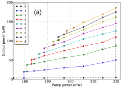
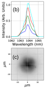
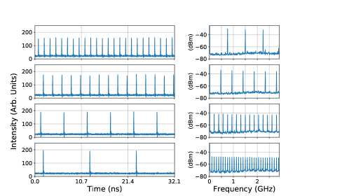
An example of several coexisting pulsating solutions are shown in Fig. 1. A regime with pulses per round-trip was observed when the pumping intensity was brought above mW. Because at this pumping value the off solution becomes unstable, this corresponds to the VECSEL threshold value. The stability of the solution appearing at threshold can be tested by decreasing the pumping power. It is observed that this regime is stable down to mW where it gives way to the pulsed solution with , see Fig. 2 (a). When the jump occurs the stability of the solution can be tested by increasing the pump power until and then decreasing it again. When increasing the pump power, one needs to take care not to cross the threshold value otherwise the system will jump back to the solution. We verified that the solution is stable for with mW. When the pumping power is decreased below we observe that a new solution with appears whose stability is similarly assessed for with mW. The same procedure allows for testing the full set of solutions branches and leads to the full bifurcation diagram reported in Fig. 2 a) featuring a staircase structure with a generalized multistability between all the pulsed emission states. This demonstrates that the system is operated in the localization regime and that up to pulses can be written in the cavity and erased individually. The RF combs in the power spectra are composed by lines whose width is less than kHz (FWHM) which is the RF bandwidth of our instrument and kHz FWHM at dB. The intensity profile of the TLSs could not be resolved by our detection system whose bandwidth is GHz. The optical spectrum analyzer trace indicates a FWHM span of nm that is independent of , as shown in Fig. 2 (b). The near-field emission of the system is depicted in Fig. 2 (c) showing the presence of single spot whose width is m (FWHM) and at the center of the pumped region.
Our theoretical approach follows the method developed in (MB-JQE-05, ; MJB-JSTQE-15, ) in which the QW active region is considered as infinitely thin and located at an antinode of the field, and the wave equation is solved exactly, in Fourier domain, within the linear sections of the micro-cavities. The dynamical model for the intra-cavity fields , where the indexes and denote the VECSEL and the SESAM, respectively, reads
| (1) | |||||
| (2) | |||||
| (3) | |||||
| (4) |
Here, the photon lifetimes are , the detuning between the two cavities is , denote the linewidth enhancement factors and are the two population inversions whose lifetimes are , . The fields injected into the micro-cavities are with a coupling efficiency given by the parameters . The two cavities mutually inject each other and their outputs consist in a superposition between the reflected and emitted fields. Considering the time of flight in the cavity as well as the presence of the beam sampler with amplitude transmission , the link between the two cavities, taking into account all the multiple reflections, is given by two Delay Algebraic Equations that read
| (5) |
We stress that the cavity enhancement factors due to the highly reflective mirrors has been scaled out using Stokes relations, making and of the same order of magnitude. This scaling has the additional advantage of simplifying the input-output relations given by Eq. 5. The minus sign represents the phase shift of the incoming field upon reflection from the top Bragg mirror. Finally, we stress that the saturation parameter in Eq. 4 contains both the ratio of the active material differential gains and of the cavity enhancement factors.
We set the photon lifetimes as fs which corresponds to nm and nm for the FWHM of the resonance, respectively. The gain and absorber linewidth enhancement factors and carrier lifetimes are and ps. The bias in the gain is varied in the interval and we set . We remark that corresponds to the maximal allowed bias experimentally as it corresponds to a peak reflectivity of . The bias in the absorber is set to and we set leading to unsaturated reflectivity of and non saturable losses of . The saturation parameter is and .
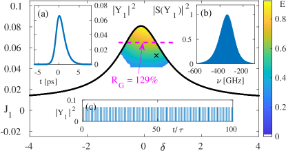
As we operate in the long delay limit, the recently developed functional mapping for PML is the most adapted method (SJG-OL-18, ). This approach is based upon computing only the so-called fast stage in the vicinity of the pulse where stimulated emission is dominant, while using the analytical solution of the dynamics during the slow stages in-between pulses, see (SJG-OL-18, ) for details. This allowed us to perform multidimensional parameter maps and we present some of our results in Fig. 3, where we scanned the region of bistability by direct numerical continuation as a function of the bias current and the detuning between the two cavities . We see that for large detuning, the lasing threshold is easily reached but the absorber is off resonance and no PML occurs as there is no modulation of the SESAM. Oppositely, the bistability region is maximal for low values of for which the modulation of the SESAM is maximal. For , the threshold is out of reach and TLSs could only be triggered by external perturbations, i.e. by injecting optical pulses. This justifies the need to operate with some minimal amount of detuning, which is in excellent agreement with the experiment. We notice in Fig. 3 (a) that a value of (i.e., nm) represents a good compromise as the threshold can be reached while conserving a wide bistable region. We noticed that the extend and the shape of the bistable region depends strongly on . They will be the topic of further studies. Finally, we present in Fig. 3 (a, b) the detail of the pulse characteristics calculated at , whereas in Fig. 3 (c) the temporal trace is depicted. We find a temporal and spectral width (FWHM) of ps and GHz (i.e., nm), respectively, leading to a time bandwidth product of 0.32. We explain such a low value by the asymmetry of pulse temporal profile, see Fig. 3 (a). Finally, the fact that simulated pulses are spectrally more narrow than experimentally can be ascribed to the fact that we did not consider the transverse spatial dynamics, which can lead to additional dispersion.
In conclusion, we presented how TLSs can be obtained in self-imaging VECSELs. The experimental realization was achieved by engineering micro-cavities with parameters that match the uncommon requirements for TLSs according to the indications of a first principle model based on delay algebraic equations. We identified how the detuning between the two micro-cavities allows to combine robust multi-stability and low threshold. We foresee that further optimization such as a SESAM with lower bandwidth and a lower saturation energy would yield an even greater bistable region. Our results have been obtained by pumping a portion of the gain mirror which is too small for achieving spatial localization. The evidence of temporal localization is an encouraging indication that Light Bullets may be experimentally observed in self-imaging VECSELs by increasing the pumped region area. To this aim, several technological issues are currently addressed, namely in terms of thermal management and pump beam shaping.
Funding information
MINECO Project COMBINA (TEC2015-65212-C3-3-P).
Platforme OPTIMAL funded by CNRS and FEDER PACA. P. Camelin acknowledge CNRS and Région PACA (Emplois Jeunes Doctorants).
References
- (1) L.A. Lugiato. Introduction to the feature section on cavity solitons: An overview. Quantum Electronics, IEEE Journal of, 39(2):193–196, 2003.
- (2) T. Ackemann, W. J. Firth, and G.L. Oppo. Chapter 6 fundamentals and applications of spatial dissipative solitons in photonic devices. In P. R. Berman E. Arimondo and C. C. Lin, editors, Advances in Atomic Molecular and Optical Physics, volume 57 of Advances In Atomic, Molecular, and Optical Physics, pages 323 – 421. Academic Press, 2009.
- (3) S. Barland, S. Coen, M. Erkintalo, M. Giudici, J. Javaloyes, and S. Murdoch. Temporal localized structures in optical resonators. Advances in Physics: X, 2(3):496–517, 2017.
- (4) S. Barland, J. R. Tredicce, M. Brambilla, L. A. Lugiato, S. Balle, M. Giudici, T. Maggipinto, L. Spinelli, G. Tissoni, T. Knödl, M. Miller, and R. Jäger. Cavity solitons as pixels in semiconductor microcavities. Nature, 419(6908):699–702, Oct 2002.
- (5) Y. Tanguy, T. Ackemann, W. J. Firth, and R. Jäger. Realization of a semiconductor-based cavity soliton laser. Phys. Rev. Lett., 100:013907, Jan 2008.
- (6) P. Genevet, S. Barland, M. Giudici, and J. R. Tredicce. Cavity soliton laser based on mutually coupled semiconductor microresonators. Phys. Rev. Lett., 101:123905, Sep 2008.
- (7) F. Leo, S. Coen, P. Kockaert, S.P. Gorza, P. Emplit, and M. Haelterman. Temporal cavity solitons in one-dimensional kerr media as bits in an all-optical buffer. Nat Photon, 4(7):471–476, Jul 2010.
- (8) T. Herr, V. Brasch, J. D. Jost, C. Y. Wang, N. M. Kondratiev, M. L. Gorodetsky, and T. J. Kippenberg. Temporal solitons in optical microresonators. Nature Photonics, 8(2):145–152, 2014.
- (9) M. Marconi, J. Javaloyes, S. Balle, and M. Giudici. How lasing localized structures evolve out of passive mode locking. Phys. Rev. Lett., 112:223901, Jun 2014.
- (10) M. Marconi, J. Javaloyes, P. Camelin, D. Chaparro, S. Balle, and M. Giudici. Control and generation of localized pulses in passively mode-locked semiconductor lasers. Selected Topics in Quantum Electronics, IEEE Journal of, PP(99):1–1, 2015.
- (11) P. Camelin, J. Javaloyes, M. Marconi, and M. Giudici. Electrical addressing and temporal tweezing of localized pulses in passively-mode-locked semiconductor lasers. Phys. Rev. A, 94:063854, Dec 2016.
- (12) M. Marconi, J. Javaloyes, S. Balle, and M. Giudici. Passive mode-locking and tilted waves in broad-area vertical-cavity surface-emitting lasers. Selected Topics in Quantum Electronics, IEEE Journal of, 21(1):85–93, Jan 2015.
- (13) A. Garnache, S. Hoogland, A. C. Tropper, I. Sagnes, G. Saint-Girons, and J. S. Roberts. Sub-500-fs soliton-like pulse in a passively mode-locked broadband surface-emitting laser with 100 mW average power. Applied Physics Letters, 80:3892–3894, 2002.
- (14) A. C. Tropper, H. D. Foreman, A. Garnache, K. G. Wilcox, and S. H. Hoogland. Vertical-external-cavity semiconductor lasers. J. Phys. D: Appl. Phys., 37:R75–R85, 2004.
- (15) U. Keller and A. C. Tropper. Passively modelocked surface-emitting semiconductor lasers. Physics Reports, 429(2):67 – 120, 2006.
- (16) J. Mulet and S. Balle. Mode locking dynamics in electrically-driven vertical-external-cavity surface-emitting lasers. Quantum Electronics, IEEE Journal of, 41(9):1148–1156, 2005.
- (17) Frank Wise and Paolo Di Trapani. Spatiotemporal solitons. Opt. Photon. News, 13(2):28–32, Feb 2002.
- (18) S. Minardi, F. Eilenberger, Y. V. Kartashov, A. Szameit, U. Röpke, J. Kobelke, K. Schuster, H. Bartelt, S. Nolte, L. Torner, F. Lederer, A. Tünnermann, and T. Pertsch. Three-dimensional light bullets in arrays of waveguides. Phys. Rev. Lett., 105:263901, Dec 2010.
- (19) J. Javaloyes. Cavity light bullets in passively mode-locked semiconductor lasers. Phys. Rev. Lett., 116:043901, Jan 2016.
- (20) S. V. Gurevich and J. Javaloyes. Spatial instabilities of light bullets in passively-mode-locked lasers. Phys. Rev. A, 96:023821, Aug 2017.
- (21) A. Laurain, M. Myara, G. Beaudoin, I. Sagnes, and A. Garnache. Multiwatt—power highly—coherent compact single—frequency tunable vertical—external—cavity—surface—emitting—semiconductor—laser. Opt. Express, 18(14):14627–14636, Jul 2010.
- (22) Baptiste Chomet, Jian Zhao, Laurence Ferrieres, Mikhael Myara, Germain Guiraud, Grégoire Beaudoin, Vincent Lecocq, Isabelle Sagnes, Nicholas Traynor, Giorgio Santarelli, Stephane Denet, and Arnaud Garnache. High-power tunable low-noise coherent source at 1.06µm based on a surface-emitting semiconductor laser. Appl. Opt., 57(18):5224–5229, Jun 2018.
- (23) C. Schelte, J. Javaloyes, and S. V. Gurevich. Functional mapping for passively mode-locked semiconductor lasers. Opt. Lett., 43(11):2535–2538, Jun 2018.