Annotation Scaffolds for Object Modeling and Manipulation
Abstract.
We present and evaluate an approach for human-in-the-loop specification of shape reconstruction with annotations for basic robot-object interactions. Our method is based on the idea of model annotation: the addition of simple cues to an underlying object model to specify shape and delineate a simple task. The goal is to explore reducing the complexity of CAD-like interfaces so that novice users can quickly recover an object’s shape and describe a manipulation task that is then carried out by a robot. The object modeling and interaction annotation capabilities are tested with a user study and compared against results obtained using existing approaches. The approach has been analyzed using a variety of shape comparison, grasping, and manipulation metrics, and tested with the PR2 robot platform, where it was shown to be successful.
1. Introduction
Embedding robots in social contexts often requires human participation in terms of decision and control. Novel situations, difficult decisions, and human preference are sure to impose new conditions to a robot’s working environment, further complicating its perception, decision, and action process. While fully autonomous robots remain out of reach, there is a clear need for appropriate ways for humans to control or influence robot actions. Human-in-the-loop (HIL) is the term used in the modeling of semi-automatic systems in which humans are used as an integral part of the design to gather data, for decision-making, or guidance.
If a human is to interact with a robot, an effective means of communication must be established through a properly designed interface. While many different types of interfaces abound, a two-dimensional Graphical User Interface (GUI) is often a necessary method of interacting with the robot and the environment in which it functions. Visualization in 2D and an interface involving Mouse-Monitor-Keyboard (MMK) is still the most used and least expensive of interfaces for Human-Computer Interaction (HCI).
While alternatives to the traditional GUIs have been proven effective, they often require special equipment, intensive training, or the use of non-intuitive methods of control. The simple 2-dimensional feedback and the tried and tested traditional input methods as well as the newer touch and gesture-based commands have been successfully applied in robotics (Rouanet et al., 2013; Singh et al., 2013).
Once a need for human participation has been identified, there still remains the question of the level of control over the robot’s decision process. Complete supervision through remote-control allows users to fully specify robot actions, reducing the need for autonomous decision-making and therefore simplifying the system’s implementation. This can be helpful when safe teleoperation is desired, like with bomb disposal (Yamauchi, 2004) or exploration of dangerous wrecks (Akal et al., 2004). While extremely useful, this type of control can be highly demanding of the human operator, and might require intensive training.
As an alternative to full control, human operators may provide guidance through the use of annotation. Annotation refers to the inclusion of supplementary information to a dataset (or a robot’s perceptual stream) that, when properly interpreted, produces a relatively large amount of additional semantic information. Examples include the addition of cues for object segmentation (Wang et al., 2012; Sengupta et al., 2013) and the indication waypoints for motion (Osentoski et al., 2010). These hints, in the form of annotations, are most advantageous when they are effective while requiring as little effort as possible on the part of the annotator. Ideally, one expects high usability and a low cognitive load. Usability refers to the annotation mechanism’s ease of learning and use, while cognitive-load refers to the mental effort in accomplishing some annotation task. The use of annotations for robot learning and operation is a rich and growing field (Wang and Hua, 2011; Kostavelis and Gasteratos, 2015). If properly designed, interfaces that allow the gathering of such annotations can help streamline robot control, as well as a valuable source of data for future autonomous systems.
One problem with designing a system with a human in the loop is that the human can make errors. Another is that a particular designated human may not be available when most needed. In terms of availability and effort, crowdsourcing offers the infrastructure to distribute the load among a host of annotators. This scheme has been successfully applied to other tasks like image segmentation and object recognition, and to help robots grasp novel objects or navigate through unknown environments (Osentoski et al., 2010; Kehoe et al., 2015a; De Croon et al., 2014). In addition, one can leverage the wisdom of crowds to extract an additional level of information about the multitude of annotation instances (Prelec et al., 2017; Hu et al., 2014). In essence, one can look at each human cue as an opinion, which could function as a simple voting system for tallying preference. A knowledge-base of annotations would then contain solutions for instances and, when considered as a whole, an implicit overview of different human approaches to each problem.
As mentioned above, one benefit of these annotations is that their use might exceed the purpose for which they were originally created. As long as the relevant information is stored in a way that could be exploited for solving a different challenge, reuse is a possibility. The reference frame for annotation can be the actor (like a robot), or the object (like a door). When annotating with the object as the reference point, the instructions address the modes of use, rather than the user’s motions. One immediate benefit of this is that object-relative annotations may be readily reused, as long as the appropriate measures are taken to allow different actors to participate. One way of creating objects for reuse is through their design and modeling using Computer-Assisted-Design (CAD). Under this approach, real or invented object models are created to represent shape, or to indicate the inner workings of a mechanism. These approach can be then extended by adding information that could indicate other modes of use. CAD, however, is a difficult discipline to learn, which indicates the need for simpler object-relative annotation strategies.
First, for an annotation system to be effective, it must capture as much of the user’s intentions as possible with the least amount of effort on their part. To accomplish this, the interface feedback and controls need to be designed to maximize human expression while minimizing cognitive load. Since user intentions vary, versatility in task annotation is desirable, that is: it should provide many ways to solve the same task, and also ways to address different tasks.
Second, the annotation system should be designed with casual users in mind, as opposed to requiring intensive training. A system that requires significant training is unlikely to find application in consumer robotics.
Third, the annotations must have impact on the target application. In our application of robotics, the annotations must be useful to accomplishing a robotics task that is considered hard for autonomous robots.
Fourth, an annotation system should feature the ability to store annotations for repeated use in the future (this is what makes it superior to continuous teleoperation), and to aggregate across the annotations of multiple users. Learning to construct these stored annotations should be easier than learning traditional CAD.
Our research is focused on the design and evaluation of a simple annotation strategy that allows HIL for two classic tasks in robotics: object modeling, and Pick-and-Place. These tasks are fundamental building blocks of a wide range of high-level tasks that a service robot is expected to encounter.
2. Related Work
2.1. Teleoperation and Simple GUI Control
Remote control may be accomplished through the use of a wide variety of interfaces (Boboc et al., 2012). These have changed considerably with the advent of Human-Centered Design (HCD) and have evolved from joystick-and-button black boxes to force-feedback devices (Farkhatdinov et al., 2010), smart gloves (Ekvall and Kragic, 2007), body-suits (Ramos et al., 2015), verbal instructions (Johnson-Roberson et al., 2011), and vision-based analysis of natural body motions (Lipton et al., 2018; Pollard et al., 2002; Fritsche et al., 2015; Ishiguro et al., 2017). While attractive, an immediate complication in using these methods is obtaining and learning to use the required equipment. In addition, mixed results from immersive teleoperation have been reported, resulting in efforts to reduce the cognitive load of the operators (Hart and Staveland, 1988). In (Martins et al., 2015) a clear trade-off was detected: greater control and situational awareness came at the cost of possible cognitive overload and impaired performance.
On the other hand, there has been a lot of effort in developing methods for reducing the cognitive load on the user in 2D-GUIs. In (Kent et al., 2017), simple constraining of motions was effective in offloading some of the cognitive effort. The familiarity and widespread use of smartphones and tablets has also brought attention to touch-based control. In (Singh et al., 2013), a simple touch-based interface was aimed at reducing operator fatigue.
Interfaces based on Monitor, Mouse, and Keyboard are a simple and cheap alternative that has been applied to a wide variety of robotics applications like robot navigation (Osentoski et al., 2010), grasping (Miller and Allen, 2004; Sorokin et al., 2010; Sucan and Chitta, 2013), or object manipulation (Leeper et al., 2012; Sung et al., 2015).
2.2. Interface Design
Work on human perception points to the fact that we process 3D objects as arrangements of 2D views (Koenderink and van Doorn, 1979; Bülthoff et al., 1995). In addition, several tasks involving shape understanding only need 2D views, like recognition and detection (Cyr and Kimia, 2004).
Display type may play a part on the ability to perform different tasks. In the work done by St John et al (St. John et al., 2001) a distinction is made between scene understanding and specific tasks involving the precise judgment of relative position. They compared pure 2D interface without projective effects to 3D displays: 2D views of 3D scenes with perspective effects. They reason that, while 3D displays seem compelling, integrated and natural, they can cause ambiguity or distortion by the nature of their presentation in a 2D display. In particular, for tasks requiring the precise relative position of two objects, 2D views proved superior.
On the other hand, Tory et al (Tory et al., 2006) argue that small cues, like shadows, can be added to pure 3D displays to improve approximate navigation and relative position. In addition, shape understanding is greatly improved by the presence of perspective views of objects. They went on to test hybrid displays (3D with 2D capabilities) in tasks involving shape understanding and relative position, and concluded that combination displays did better than strict 2D or 3D displays. They determined that perspective views help with 3D integrated spatial tasks while 2D views help with precise actions requiring concentration and the understanding of relative position.
2.3. Annotation
Informative annotation can be obtained from users in several ways. One possibility is to add tags and qualifiers to a dataset after it has been acquired. This can range from intensive human labeling in post-production to methods that require minimal markings. Full image segments are drawn by humans and used as ground truth in (Martin et al., 2001), whereas in (Wang et al., 2012), the segmentation algorithm needs only an initial seed point provided by a human. In 3D environments, human-segmented data is often used for training and validation (Rodolà et al., 2013). Simple hints have also been used in these environments to seed automatic segmentation algorithms (Nguyen et al., 2017). Annotations can also be used for tracking objects in 3D from an initial seed labeling (Teichman et al., 2013). In (Zivkovic et al., 2008), an annotated dataset is constructed for robot navigation.
Learning from Demonstration (LfD) offers an alternative to the active addition of annotations in post-processing. In LfD, the parameters of actuation are implicitly refined through the observation of examples provided by humans. This happens because under this strategy, perception-action systems are built specifically to follow human actions and replicate them within their own circumstances (like different kinematic structures or safety constraints). See (Argall et al., 2009) for a thorough review.
A third approach is kinesthetic teaching, where an operator indicates appropriate motions by physically guiding the robot while it records the event (Akgun et al., 2012). Alternatively, the robot may be guided virtually, aided with a variety of feedback options (Ruffaldi et al., 2017; Restrepo et al., 2017).
In one sense, annotation can be obtained without human supervision by automatically processing the data and extracting useful intelligence from the collected information. Metadata can be analyzed as a form of annotation for the payload it describes. Often, the input data itself comes from data sources rich with explicit or implicit human annotation. In (Patron-Perez et al., 2012), automatic classification methods are trained using existing human-interaction datasets that have been previously grouped by activity. While effective in its own right, this type of unsupervised learning needs to be validated before being put to used in any context where safety, preference, or informed judgment is required. One problem with unintentional annotation is that it is unstructured and noisy by nature, making the extraction of usable intelligence a considerably more difficult proposition (Fu et al., 2012). When possible, it is preferable to use annotations that are directly aimed at enhancing the understanding of a situation or task that one intends to refine.
2.3.1. Annotation of Perceptual Data
There are different mediums for annotation that the robot may provide or use as input for operation. When using kinesthetic learning, the system focuses on the recording of changes in its joint space with respect to a given objective (Akgun et al., 2012). While useful, it is usually more powerful to also have a way of capturing the surrounding environment. A common approach is to use visual perception of some kind. This is due to the enormous amount of relevant information that may be extracted from this approach. It may capture color, changes in spatial and temporal relations, and importantly, it’s a perceptual stream that we as humans generally favor to analyze our environments. Annotation of images has a long tradition in robotics. For traditional image stills or streams of images (2D), large databases have been constructed for segmentation (Martin et al., 2001) and object recognition (Caltech, [n. d.]; Antonio Torralba, 2018). More recently, stereo vision and depth sensors have extended the perceptual stream to 3D. In this realm, several annotated databases have been constructed (3dW, 2018; Chang et al., 2015). The volumetric and color information has been used for object recognition (Xiang et al., 2016), tracking (Teichman et al., 2013), or shape reconstruction (Nguyen et al., 2017).
Off-the-shelf sensors like the Microsoft Kinect give easy access to these input streams, and have made the 3D scanning of environments and objects ubiquitous. Several algorithms have been developed and refined to allow the integration of depth sensing onto unified models of the scenes they capture (Han et al., 2013). The Kinect Fusion algorithm (Newcombe et al., 2011), and its many variants (Whelan et al., 2012), allow the tracking of a scene and integration of captured depth-frames into a coherent volumetric representation. Some variants have even accomplished deformation and part-tracking (Dou et al., 2015). One important aspect of the models that these approaches create is their sensitivity to the sensor and the context. The Kinect has a resolution of about 2 mm and has trouble capturing thin surfaces, transparent or shiny objects and requires careful scanning or large amounts of computation for dealing with noise. While various techniques exist to deal with these problems, when these appear in conjunction to context-dependent constraints, human annotations become highly valuable. For an in-depth review of automatic and semi-automatic methods of reconstruction from point clouds, see (Berger et al., 2017).
2.3.2. Annotations and Crowdsourcing
Annotations that help solve particular instances of problems can be gathered into a knowledge-base that can, in turn, be studied to gain insights into the solving of more general situations. One way to gather a large amount of usable annotations is to take advantage of the growing infrastructure for crowdsourcing tasks, like Amazon’s Mechanical Turk (Buhrmester et al., 2011).
The use of the public for the annotation of robotic tasks imposes a series of additional conditions on the annotation interface as well as the level of required user effort, expertise, and precision. Simple methods must be developed for non-experts to participate. Existing technology can simply use human guidance to refine world models. In (Chen et al., 2015), crowdsourcing is used to construct maps by tracking the motion of smartphone recordings of indoor environments. One immediate requirement is that the necessary input device be readily available and preferably of intuitive use and design. That is why point-and-click or touch-screen interfaces have been so widely used for this purpose. In (Nguyen et al., 2017), a robust annotation tool is provided to segment captured 3D data. In (Sorokin et al., 2010), crowdsourcing was used to segment, classify and evaluate 2D and 3D objects for grasping. A series of computer vision problems are addressed using human computation in (Gingold et al., 2012). See (Kehoe et al., 2015b) for a comprehensive survey of cloud robotics, which includes several applications using crowdsourcing. In (Hu et al., 2014), multiple labels are used to combine annotations in a simple voting scheme that can help deal with inconsistent or erroneous labeling. Advances in automatic methods and annotation have developed into powerful hybrid methods that can achieve a variety of tasks combining the best of both worlds (Russakovsky et al., 2015).
2.3.3. Annotation and Cognitive Load
One important aspect of GUI design is to consider the user and the objectives. Several studies have looked at what humans can and can’t do in these robotics tasks, what interaction exists between an individual’s abilities, and what the interface can do (Hart and Staveland, 1988; Oviatt, 2006). In addition, studies involving tasks in 3D space usually consider human natural abilities or previous experience in similar environments (Leeper et al., 2012). Indeed, studies suggest that spatial reasoning ability not only varies between individuals, but that different tasks might require different abilities within the realm of spatial reasoning (Vandenberg and Kuse, 1978; Blazhenkova and Kozhevnikov, 2010). One common precept in HCD is to avoid visual clutter in order to lower cognitive load. Studies have found that novice users get better results on interfaces that hide extraneous features (Reis et al., 2012), and where they only focus on the high-level tasks while the robot controls the low level details (Enes, 2010).
2.4. Task-Oriented Annotation
In the field of annotations for robotic tasks, there has been intense research under both the sense-plan-act, and behavior-oriented approaches. On one hand, there is perception-stream annotations for 2D and 3D data.
2.4.1. Annotation for Object Reconstruction
Object reconstruction refers to the recovery of a real object’s structure in digital form from some stream of perceptual data. Significant progress has been made in automatic reconstruction. One of the general methods consists of using multiple 2D views of an object to obtain its shape (Dyer, 2001; Moons et al., 2009). While this approach allows the use of monocular cameras, depth-annotated images have become easily accessible and allow for accurate pose estimation and refinement of models (Sun et al., 2013). The work of Newcombe et al (Newcombe et al., 2011) used the Microsoft Kinect sensor to integrate depth-augmented images into a single volumetric model of the scene. This approach was very successful and has been used and refined extensively (Whelan et al., 2012; Dou et al., 2015; Zhang et al., 2014).
The main problem with automatic reconstruction is its sensitivity to input resolution and any noise or artifacts the sensor might cause. A well known problem has to do with the natural difficulties in dealing with thin structures, noisy scans, or shiny or transparent surfaces (Ummenhofer and Brox, 2013). Several algorithms attempt to combat these problems by imposing correction mechanisms to preserve shape or inferred structure (Sharf et al., 2007; Li et al., 2011; Lafarge and Alliez, 2013).
An alternative to automation is full manual reconstruction or object modeling. Examples of this approach can be found under the category of CAD. Several programs of varying complexity have been developed to construct 3D shapes and have been used in digital object construction and animation (sol, 2018; Autodesk, 2018). These programs are usually quite powerful but prohibitively complex for crowdsourcing. Learning them is also quite difficult, with basic courses ranging from a few weeks to a couple months.
A third option is semi-automatic reconstruction. Here, the idea is to use human cues to seed or refine automatic methods. These can work on 2D images, like the work of Chen et al(Chen et al., 2013), where simple human marks on 2D images may result in the creation of 3D objects. The work of Kholgade et al(Kholgade et al., 2014) integrates simple annotations on 2D images with 3D object models extracted from a repository to extract complex objects from 2D scenes. Another approach is to work directly with 3D scans of a scene. This can either be on the depth-based point clouds or the reconstructed mesh. In Arikan et al(Arikan et al., 2013), simple cues help snap planar primitives on top of point cloud sections in order to build simple architectural models. In the work of Nguyen et al(Nguyen et al., 2017), annotations are made on reconstructed 3D models of the whole environment to generate segmented 3D scenes. In the work of Sharf et al (Sharf et al., 2007), topology-aware reconstruction is first attempted automatically, and then iteratively corrected with human input. A refined interface showing a similar approach is shown in the work by Yin et al (Yin et al., 2014).
One important distinction between methods is the form these annotations take. In (Nguyen et al., 2017; Chen et al., 2013) simple lines and sketches are interpreted as instructions and combined with the section of the images they are used on. The results are either 3D models of the 2D-segmented shapes, or a segmented 3D space, where each part of the scene may be labeled with the object categories. Another typical objective is the creation of new object models from existing ones. One approach is to deform them into new shapes. In the work of (Nan et al., 2010; Zheng et al., 2012), cuboid proxies are used to guide shape deformations.
The idea of using shape proxies for future actions over the base shape is, in a sense, a method of annotation. In the work of McCrae et al(McCrae et al., 2011), a slice-based proxy was developed for representing 3D meshes. These were placed by humans and later used as training input for an automatic planar-proxy creation algorithm. The potential applications range from printing simplified 3D objects to the annotation and recovery of 3D shapes. In a follow-up work, McCrae et al (Mccrae et al., 2013) used these planar proxies, in conjunction with crowdsourcing to study user abilities regarding estimation of surface normals in commonly occurring 3D object models.
A swept surface is the area resulting from moving a line, which can be closed (contour) along a path. These can be translational, rotational or a combination of both. They can even apply to solids. A generalized cylinder (Binford, 1975) is a type of translational swept surface that parametrizes the characteristics of the surface depending on its position along the sweep. If the resulting surface encloses a volume, then the resulting shape can represent a solid in 3D. Some examples of shapes that can be created this way are shown in Figure 1. For the purposes of this work, all mentions of sweep-based objects refer to generalized cylinders.
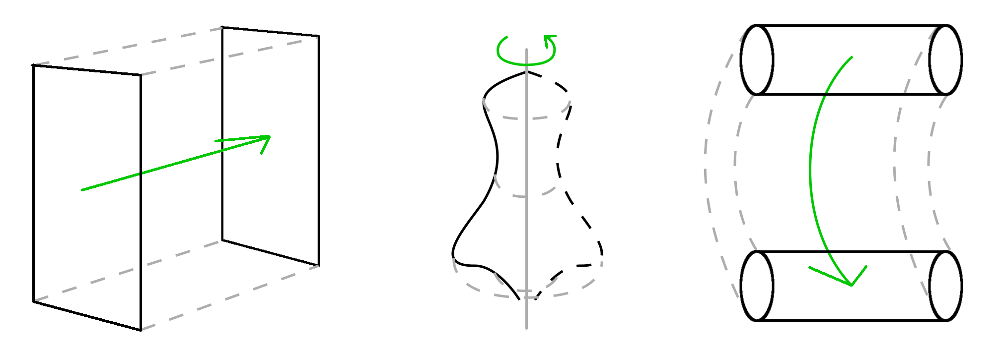
In the work of Yoon et al (Yoon and Kim, 2006), a sweep-based proxy is extracted from 3D object meshes and later used to deform them by performing simple modifications of the underlying proxy. This approach highlights the power of simplified representations for object analysis and modification. The work of Shtof et al (Shtof et al., 2013) shows the use of these simple sweep-based proxies to fit 2D sketches and transform them to 3D objects.
Yin et al (Yin et al., 2014), developed an annotation scheme that uses simple gestures and the structure of object point clouds to infer a set of underlying part proxies that can be modified to reconstruct the shape. This gesture-based reconstruction approach can help deal with incomplete scans and was designed specifically to offer the best trade-off between user-effort and shape quality. The inference of underlying shape is carried out automatically, with some parameter tweaking done by the operator. One disadvantage is that this automatic reconstruction has trouble dealing with multiple small holes or with topologies that contain cavities, like mugs or bowls. A similar approach has been used to segment meshes into generalized cylinders (Zhou et al., 2015). Two typical topology-related problems are objects missing cavities, like a mug without a cavity (Yin et al., 2014) or unexpected topologies like mugs with various holes (McCrae et al., 2011).
Sweep-based object representations have a long history in the study of shape and perception. They have also been called generalized cylinders (Naeve and Eklundh, 1995), and together with implicit volumes, constructive-solid-geometry (CSG) and boundary representation, constitutes one of the main strategies for representing shapes. Part of their appeal is that they are intuitive, simple, easy to generalize and scale into more complex shapes. It also allows many parameters of the resulting solid to be easily calculated (Ballard and Brown, 1982). They have also relatively straightforward conversions to surface representation and shape skeletons (Huang et al., 2013), which are useful alternatives when dealing with 3D objects.
2.4.2. Annotation for Object Grasping
Robotic grasping has been attempted automatically in several ways. These approaches vary in the level of dependency on existing information repositories.
Some studies avoid using object models and use the perceptual input directly to extract grasp affordances (Piater et al., 2011). In (Popović et al., 2011), local surface features are used to propose grasps. Some techniques use a multitude of heuristics to generate grasp hypotheses from the sensed point clouds of the scene (Hsiao et al., 2010). These approaches are, in a way, model-less and allow the grasping of objects by their current appearance. An alternative approach uses object models to store and seed the inference of grasps. In the work of (Ciocarlie et al., 2007; Ciocarlie and Allen, 2009), Ciocarlie et al., develop a technique called Eigengrasps where low-dimensional grasp subspaces are computed that match the object shape. These in turn may be used for seeding interactive grasping approaches. Some approaches are denominated hybrid, since they use appearance features or 3D-model detection depending on the situation (Brook et al., 2011). While automatic grasping is a promising field, context and functional requirements might place additional conditions on the choosing fo a specific grasp.
A slightly less “independent” procedure is to match and apply grasping templates to the sensed input (Herzog et al., 2012). For graping based on existing knowledge-bases, one option is to detect known objects followed by executing a specific grasp linked to that particular instance or that category of objects (Dang and Allen, 2012; Azad et al., 2007). In (Miller et al., 2003), shape primitives are linked to the target object and used to seed appropriate contact-level grasping.
Databases of grasping examples may be used as a starting point for automatically generating a grasp hypotheses (Li and Pollard, 2005). While these approaches are not fully automatic, they already contain important semantic information that might be germane to a multitude of context-dependent grasping tasks. In (Dang and Allen, 2012; Nikandrova and Kyrki, 2015), shape and objective constraints are used to specify appropriate grasps.
Humans are excellent at quickly arriving at functional grasps, even for novel objects. We have the advantage of context and experience to help guide our choice. Whether for direct grasp suggestions, or for creating labeled model data, human annotations have been widely used. Human action may be observed and used under the LfD strategy and then processed to generate robot grasps (Romero et al., 2009). Alternatively, human input can serve to label grasping databases or to interactively choose grasps (Ciocarlie and Allen, 2009). In summary, a range of automatic and interactive methods exist that can use either raw perception and automation or existing models to obtain grasps. For a survey on data-driven grasp synthesis, see (Bohg et al., 2013).
Teleoperated grasps can be done combining two general methods: using a GUI to indicate waypoints (Sucan and Chitta, 2013), and contact-reactive mechanisms to refine the mechanical aspects of that particular grasp (Hsiao et al., 2010). Force-feedback can help the user get a sense of the grasp resistance and object malleability during the interaction (Khurshid et al., 2017).
Significant effort has been placed on obtaining a taxonomy of types of grasps and to judge their physical qualities (Cutkosky, 1989; Feix et al., 2016; Liu
et al., 2016). These studies draw inspiration from early analysis of human grasping (Napier, 1956) or robot hands (Li et al., 1989). One widely used approach for judging grasp quality is that of the metric developed by (Ferrari and Canny, 1992). It uses the grasp contact points to construct a convex hull over the set of wrenches that can be applied with the given grasp. This is called the Grasp Wrench Space (GWS).
Two measurements that can be used are the volume of the computed convex hull and the radius of the maximum sphere contained in it, which we call the epsilon-distance, or -dist.
These indicate the robustness of a grasp and the
versatility of the
wrenches applicable for the given grasp. One popular tool used in the literature to evaluate grasp quality and generate grasp candidates is GraspIt! (Miller and Allen, 2004). It uses the GWS volume and metrics to rank grasps that have been generated using a variety of grasp-planning techniques including the above mentioned Eignegrasps.
While several methods abound that use existing 3D mesh objects or that detect them from 2D-views or point clouds, less effort has been paid to linking grasps to simpler shape representations or proxies like the ones obtained in (Yoon and Kim, 2006; McCrae et al., 2011). As mentioned previously, these proxies are compact versions of objects, and can be used to represent categories as well as instances, and help indicate shape, as well as topology. Linking grasps to these might work as a sort of look-up table for grasps.
2.4.3. Annotation for Object Handling
Grasping and manipulation are closely related. For some grasps finding the final contacts of the gripper is insufficient. In several tasks, the approach to accomplish the grasp, as well as the task-dependent manipulation that will be performed affect the generated grasp hypotheses. Some studies have looked at shape category and the physical context to determine manipulation constraints (Nikandrova and Kyrki, 2015), while others have used human experience to seed approach vectors (Ekvall and Kragic, 2007). In (Dang and Allen, 2012), a grasp planning algorithm is used in conjunction to a set of task-dependent semantic constraints to choose grasps, which in turn may inform the approach vector. These semantic constraints are extracted from example grasps and then used to construct a semantic affordance map which directly relates the object class (obtained from object depth information) to the approach vectors and different task-appropriate grasps. This provides evidence that relating object instance or category models to manipulation annotations is of great utility.
In terms of obtaining grasp and manipulation examples, annotated databases or human-examples may be used. Several studies have focused on using human input to learn or validate manipulation tasks. The work by Kent et al (Kent et al., 2014) uses crowdsourcing of manipulation tasks to reconstruct 3D object models (as integrated point clouds) with grasp points attached to them. This approach demonstrates the power of crowdsourcing techniques to complex tasks in robotics. It also represents an example of semantically-augmented object models that can be later used for solving tasks.
One popular tool for motion planning is Moveit! (Sucan and Chitta, 2013). This tool can be used within the larger Robot Operating System (ROS) to perform automatic motion planning with collision avoidance. This may also be used in conjunction with a manipulation interface that humans can use to indicate motions. In the work by Leeper et al, (Leeper et al., 2012), this interface was used to analyze manipulation strategies for indicating grasps and grasp approach methodologies. They compared continuous teleoperation against three other strategies with varying degrees of autonomy. They showed than a combination of manual annotation and automatic processing resulted in the greatest success rate. This is supported by the work done by Hertkorn (Hertkorn, 2016), where the importance of shared workload is thoroughly analyzed in the context of grasping and manipulation.
2.4.4. Annotation Usability Studies
We based our object modeling usability study on similar studies involving interactive shape reconstruction from point clouds (Sharf et al., 2007; Nan et al., 2010; Arikan et al., 2013). These constitute the state-of-the-art on this type of interactive approaches (Berger et al., 2014, 2017). In these studies, user interactions with their software are logged and timed, and later analyzed for precision errors. In (Sharf et al., 2007; Nan et al., 2010), an expert user illustrates the possibilities of their interface, while in (Arikan et al., 2013), five users are tested. Similarly to these studies, we recorded action choices and timing and evaluated shape quality. We also chose to include an expert user to show the possibilities of the interface if enough time is devoted to learning it.
In the area of object handling, the work by Hertkorn (Hertkorn, 2016) has one study with a similar objective (evaluating the effect a particular grasping assistance technique). In this study, participants were were asked to complete grasp trials each. Basic shapes were chosen to attempt to eliminate the effects of shape complexity on the interface’s effectiveness in assisted grasping. Similarly, we chose to use simple and/or familiar basic shapes.
Weisz et al (Weisz et al., 2013) uses a database of preplanned grasps, as well as an online planner to help a user find appropriate grasps. Time and success rate was computed for five subjects attempting three tasks. While five subjects is a small number, results indicate trends and allow the research to hone in on the appropriate refinements for a more in-depth evaluation.
The work by Leeper et al (Leeper et al., 2012) is designed to compare different interaction strategies for attaining valid grasps using the PR2 robot. In this study, participants were asked to grasp as many objects as possible (between and ) in three rounds of trials. Participants were shown a tutorial before the start of the trial.
In the work of Sorokin et al (Sorokin et al., 2010), several tasks and trials were tested using crowdsourcing. Here, the annotation tasks were simple in order to allow testing the approach, and later integrated with the ultimate objective of completing pick-and-place tasks. They found that in many cases a single average “worker” produced poor results, but that by cleaning and averaging of them, high accuracy was obtained.
The work by Rouanet et al (Rouanet et al., 2013) uses a simple protocol that involves input and output surveys, a tutorial, and a challenge section. While they were focused on evaluating different methods of directing robot motion and attention, we used the same protocol structure for our own annotation tests.
3. Methods and Experimental Design
In this section, we describe the design rationale behind the Point Cloud Scaffolds (PCS) and the Point Cloud Prototyper (PCP). In addition, we describe the user study used to evaluate the annotation interface and subject’s abilities in the tasks of object modeling, grasping, and pick-and-place.
3.1. Point Cloud Scaffolds
3.1.1. Getting Point Clouds
Given the availability of popular and inexpensive depth-sensing equipment, we decided to base our reconstruction effort on RGB-D technology. The Point Cloud Library (PCL) (Rusu and Cousins, 2011) provides a large set of methods and a well maintained API for working with point clouds. It seamlessly integrates with the Microsoft Kinect, perhaps the most popular sensor in its class, and has a large community behind it.
The Kinect sensor can take snapshots of a scene at a resolution of 640 by 480 pixels. These Red-Green-Blue (RGB) images can be registered to a depth map in a way that causes each pixel have three color dimensions (r,g,b) plus three spatial dimensions (x,y,z). While extremely rich, this raw input needs to be processed and corrected to overcome the natural noise and resolution limitations of the sensor. In particular, registration is not perfect, which means that the color image might not be overlaid exactly on top of the depth map, causing some pixels to contain the wrong color or and for others to have no depth. This is a consequence of the mechanism for obtaining the depth, which uses an RGB camera and an Infra-Red (IR) emitter-receiver pair at very close - but different - locations. The fact that the Kinect uses an IR emitter and sensor to capture depth, also means that it is sensitive to scene characteristics affecting this approach. Specular reflections, like those present in shiny objects impede depth sensing. Also, objects made of glass or clear plastic are not detected properly. Resolution is also an issue, since the Kinect can capture differences down to only about , which means that thin structures like nets, cables, or leafs are often invisible.
A single snapshot can capture only what it can see from one point of view (POV), which means that only parts of the scene are captured. This can be called -D. While a good Red-Green-Blue-Depth (RGB-D) snapshot might be enough for a human to understand and interpret, the missing information makes the automatic recovery of the object structure a difficult task. One option is to capture multiple snapshots from different points of view and then registering (coalescing) them offline. This is where the Kinect Fusion approach proves extremely useful. PCL contains a version of the Kinect Fusion algorithm from Newcombe et al (Newcombe et al., 2011), called Kinfu. Kinfu uses each depth-frame to correct a running occupancy model of the scene by assigning an occupancy weight to the voxelized environment. The only requirements are that there is sufficient spatial texture in the scene and that the scanning is done in a relatively smooth way. Spatial texture means non-smooth changes in the geometry of the scene. This is needed for the algorithm to have clearly identifiable characteristics that can be matched to the current view. Smooth scanning is needed because jumps in the position or the POV make the current view and the running model too different to match quickly. The matching algorithm, called Iterative Closest Point (ICP), needs the structures to be matched to start in relatively close positions to avoid falling into local minima. In the end, a voxelized space is iteratively refined to carve out areas that are not occupied. This model can be converted to mesh or point cloud form and used to represent the scanned space. While Kinfu is extremely powerful, it cannot model occluded areas of the scene, like internal structures or hard-to-reach spaces in the environment. In addition to the above mentioned issues with noise and resolution, object models are often incomplete or noisy. This is where human annotation comes in.
The idea is simple: Scan a scene and extract a point cloud of the objects of interest; then “trace” the desired shape over this initial scan to refine and model the virtual object. The concept of tracing refers to the one used to replicate 2D images, where one can place a translucent piece of paper over the original design and draw over the important features. While the resulting image might contain less details than the original, the tracer does not need any of the expertise from the original creator and can focus on exactly the details they might consider relevant. The challenge is that this approach needs to be migrated to 3D, where the point cloud can serve as the “original” and the object is to come up with an equivalent to the translucent paper to recreate the shape. One approach is to simply use projections of the shape into 2D-planes that can then be analyzed to extract the desired contours. The problem with this approach is that cavities and internal structures will not be visible. This, however, is a good starting point for the design of a 3D trancing scheme. In the following section, we relate the steps taken to construct a tracing overlay, which we call a Point Cloud Scaffold, to accumulate important contours and capture possible cavities and internal structures.
3.1.2. Scaffolds for 3D Tracing
A tracing overlay for point clouds needs to be a simple structure that can collect as much (or as little) information as the tracer chooses. It must also follow some intuitive tracing mechanism that can work for a variety of shapes and levels of exactitude. As mentioned above, contour sweeps have a long history in computer science and are understood to be versatile, yet simple and intuitive structures. Complex or organic looking shapes may be created using a contour swept along a path fitted over a 3D shape, like in the work of Zhou et al (Zhou et al., 2015).
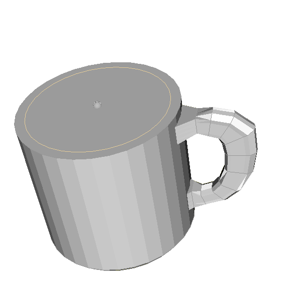
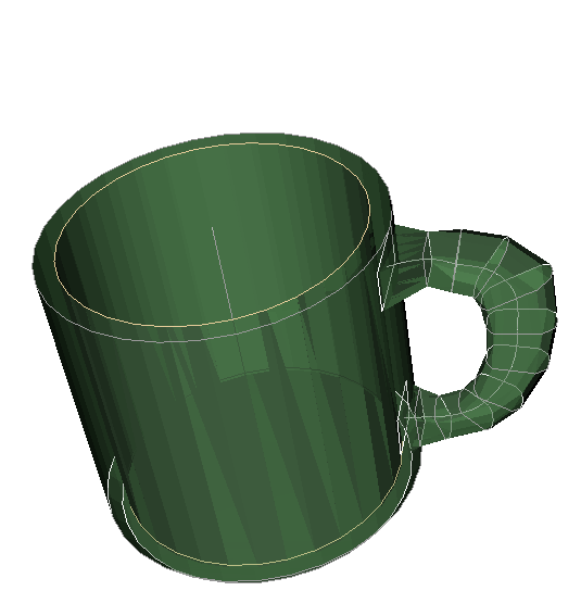
A swept surface is the result of integrating into a volume the space occupied by a planar shape as it moves through it. A circle swept along a straight line creates a cylinder, while a square would create a prism. This approach can be extended by allowing the swept shapes to change scale, shape, or even to contain internal holes. There are several research avenues that use this approach to describe or reconstruct shapes (Schroeder et al., 1994; Osher and Fedkiw, 2001; Abdel-Malek et al., 2006; Yin et al., 2014; Zhou et al., 2015). The description of such a structure can be done explicitly (by placing structural features that control the shape and the path of the contours), or implicitly (by constructing some sort of analytical description that can be queried at any point of interest). Given its intended use (human editing) we chose to describe the sweeping structure explicitly through contour and path features. Figure 2 shows the parts of our sweep based structure, which we call: a Point Cloud Scaffold.

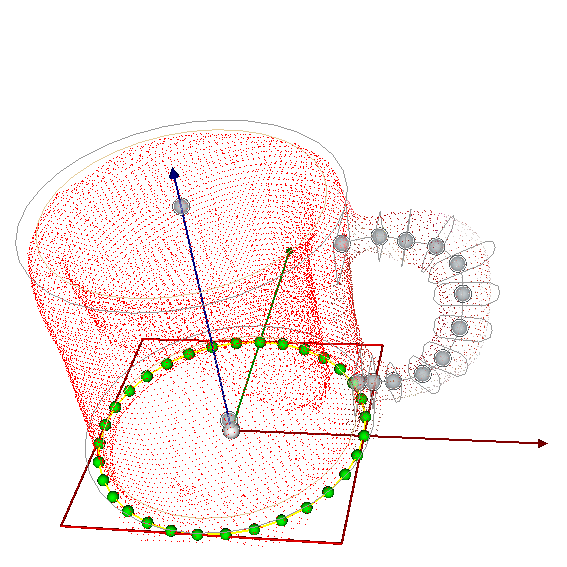
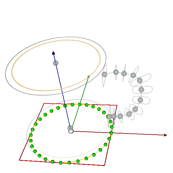
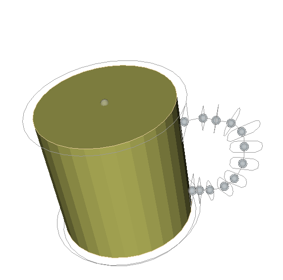
To describe a contour, we used a closed interpolating spline using a Cardinal basis (Schoenberg and Sharma, 1973). This types of objects describe lines in space that can be defined piece-wise and controlled by a set of points over their domain. This spline is described over a plane and then transformed to occupy any location in space. In our implementation, we control the spline shapes using a series of control points (also on the plane) that can either form part or be outside of the spline itself. Since we want the points not only to control the shape, but also to form part of it, we use a form of splines that interpolate these points into a closed and continuous curve. In Figure 2a, the (red square) contour, as well as the (green sphere) control points can be seen.
Once two or more of these contours are defined on different planes, these can be connected in a sequence to form a complete scaffold. To form the volume, the contours must connect to those before and after them until the whole object is closed. We used a simplified linear interpolation between consecutive contours, which allows very simple implementation and can be quickly refined into complex shapes. Figure 2d shows the closed structure resulting from joining the contour planes of the two different scaffolds, which can be seen by themselves in Figure 2c.
A possible extension for extending the topology of the initial volumes is to allow the path to be closed, meaning that the swept contour returns to itself to form a closed path. This would easily allow the creation of tori or similar objects.
Finally, we included the possibility of adding a second closed spline to every plane. This second spline constitutes a planar hole that can also be connected to contiguous holes to create volumetric negative spaces. This simple scheme allows the creation of basic internal structures that would otherwise remain unspecified if automatic POV-based reconstruction was used by itself. This mechanism can also be extended to include more internal complexity by adding alternating layers of positive and negative spaces. Figure 2e shows the whole (negative) volume. The positive and negative volumes can be intersected (as in Constructive Solid Geometry) to generate a complex final structure with cavities (Figure 2f).
All methods for interacting with the scaffolds will be described in the prototyping module of the description of PCP. It is worth noting that the use of point clouds as a basis for the sweep-based scaffolds is for the implementation of PCP as a proof of concept. The idea of sweep-based annotation scaffolds is potentially extensible to other 3D spatial occupancy representations like the one in the work of Wurm et al (Wurm et al., 2010).
3.2. PCP: The Point Cloud Prototyper
3.2.1. PCL Interface Design
We use the tracing analogy as a method of constraining user interaction to a reduced set of operations. Some tracing actions require focused attention on the position of parts and the distance relations between objects. From previous research (St. John et al., 2001; Tory et al., 2006), it is known that 2D views are better for these types of position-dependent tasks, while 3D perspective views are preferable when dealing with high level scene understanding. We therefore utilized a type of interface that can accommodate these two types of actions. For general scene visualization and navigation, 3D perspective views are used. For precision tasks, users were able to work either under orthographic views, or directly constrained to edit scaffold elements in a plane.
3.2.2. PCL Implementation
PCP is based on an early project from the Point Cloud Library called “Cloud Composer” (clo, 2018) developed by Jérémie Papon (Papon, 2012).
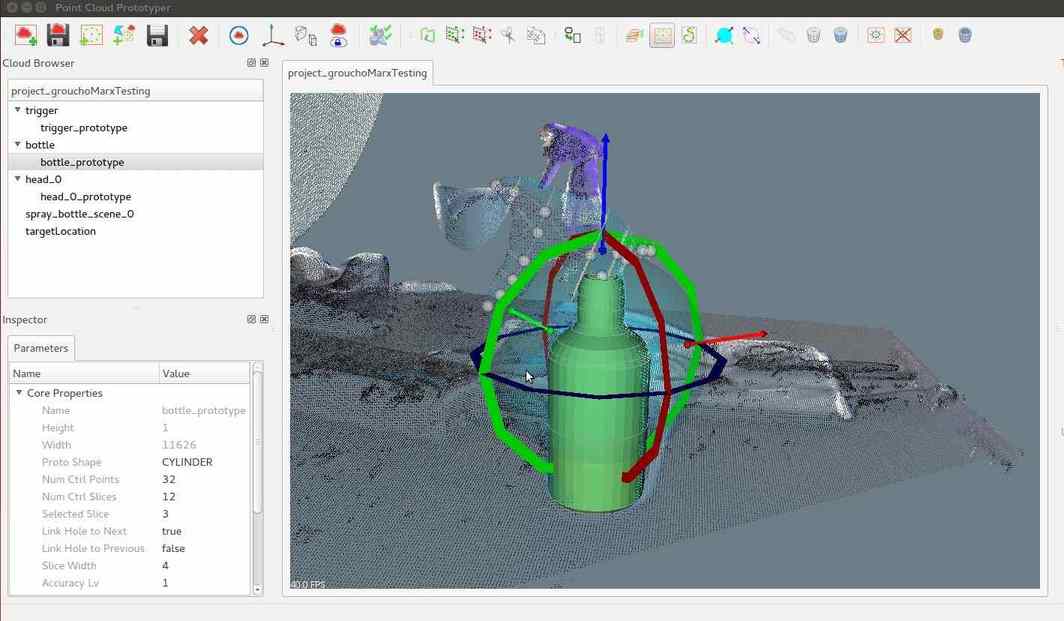
PCP has three main modules: point cloud editing and visualization (which was the purpose of the original cloud composer from PCL); object modeling using scaffolds; and manipulation using a gripper widget and a joint mover. In this work, we describe the object modeling and manipulation modules.
3.2.3. Point Cloud Visualization and Editing
The Cloud Composer project uses PCL’s PCLVisualizer to display and keep track of point clouds and meshes. It is also built in a way that allows the inclusion of plugins that may serve as filters or processing tools for point clouds. These include filters like cloud sanitizing and voxel grid downsampling; feature estimation like normal extraction; and segmentation actions like euclidean clustering and supervoxel extraction. While these filters are useful and can be integrated into the shape reconstruction workflow, we chose to refrain from their inclusion since we wanted to see what could be accomplished from user tracing over raw input clouds.
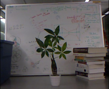
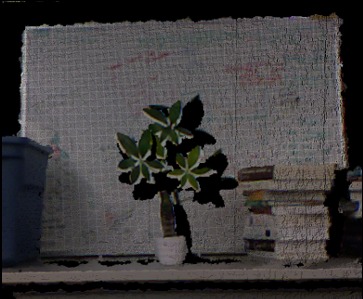
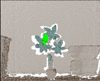
Cloud Composer has a basic interface for applying the filters and editing the clouds. We made several modifications to the existing interface to improve clarity and interaction. One important addition to this module was the inclusion of a polygonal point selection tool to select parts of point clouds. This allowed users to precisely segment a scene into areas and objects into parts, each of which can be modeled independently. In addition, we included methods for hiding point clouds or preventing their modifications, which allowed users to have visual markers for understanding the scene, without running the risk of having visual clutter or causing unintentional changes. While RGB-D frames carry the scene’s colors, we also added the option to paint clouds differently for added clarity. Lastly, we performed several minor changes to the way some actions were called or the details of their execution. For example, we added buttons for centering the view of clouds, or switching the projection from perspective to orthographic. Figure 4 shows the sequence of steps to scan a scene Figure 4a to obtain a cloud Figure 4b , and segment the resulting cloud using the point cloud editing tools Figure 4c.
3.3. Annotations for Reconstruction
3.3.1. Inserting Scaffolds
The first step was adding the scaffolds as new editable items. We followed a hierarchical approach where the full scaffold is composed of planar contours called slices which are in turn determined by control points or handles. As this tool is focused on reconstruction from point clouds, each scaffold needs to be directly connected to an underlying cloud. This is easily modifiable in case parts need to be added which, for some reason, have no point clouds to be attached to. This, however, was not a requirement since we wished to reconstruct shapes that were only mildly incomplete or had holes. While this point-less modeling extends the capabilities of the system, it moves more closely towards the approach used in CAD, which we did not want to emulate.
Two methods were tested for fitting PCS to point clouds: insertion through oriented bounding box (OBB), and POV-insertion through crosshairs. OBB-insertion first needs to obtain an oriented bounding box, which is a bounding box where the three orthogonal directions run along the principal directions of change in the point cloud. This can be easily computed using PCL, and used to place a scaffold. The scaffold could be placed in such a way that the slices ran along the axis with the greatest change. After insertion is performed, a user may change the direction of the scaffold (switch the direction the sweep follows), or permute the position of the scaffold inside the box (switching the direction of sweep among the three main axes of the bounding box). While this approach proved successful in fitting regular and elongated shapes like long cylinders or prisms (like a baseball bat), it proved impractical when dealing with more compact shapes (like an apple).
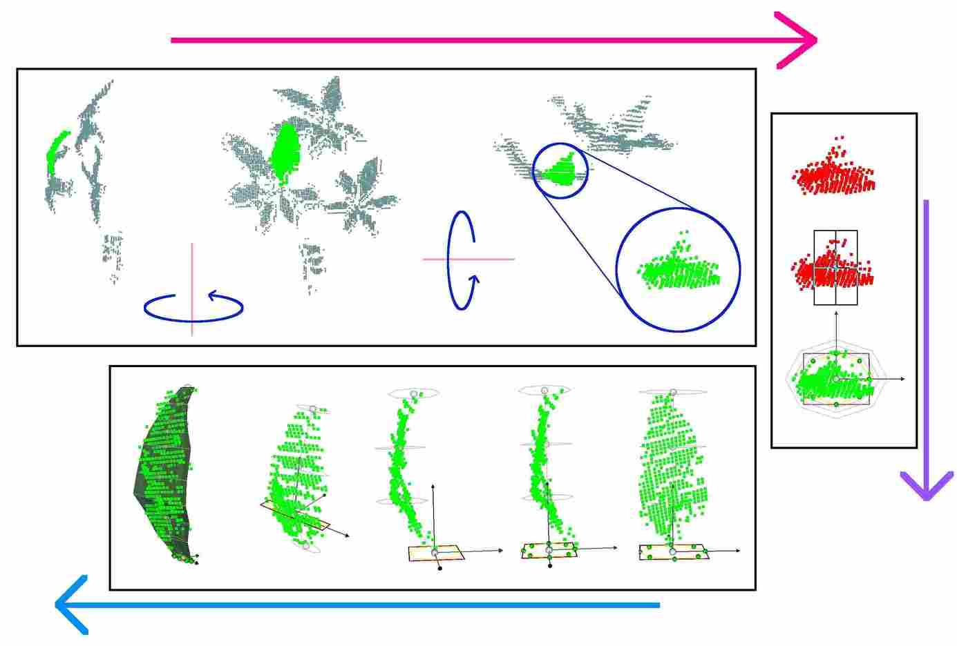
POV-insertion follows the idea that a user can choose and quickly identify the sweep direction for a shape. For instance, a user could quickly pick the sweep direction for both a baseball bat and an apple regardless of the length of the shapes. The steps are: ) the user places the view along the direction of the sweep, ) chooses one of two scaffold primitives (cylinder or box), and ) executes the scaffold insertion. This can be done in three quick actions with minimal delay. The insertion process analyzes the structure of the point cloud to refine the positioning of the scaffold around it. It will place the first and last contours at sufficient distance to exactly cover the nearest and furthest points, and will change the area of the cross section (the slice widths and heights) to encompass the chosen point cloud. Figure 5 shows the whole process of segmenting the point cloud from Figure 4, setting the POV, inserting the scaffold, and editing its shape to generate a curved object.
3.3.2. Editing Scaffolds
As mentioned above, several tasks involving 3D tracing require focus on positions and distances, for which we provided embedded interaction modes in 2D. As previous research has found (Kent et al., 2017), constraining interactions can help focus users and lower cognitive load.
Editing the slices:
the contours in each slice can be independently translated, rotated and scaled using an arrow and disk transform widget that is highlighted for each slice.
Editing the Sweep-Axis:
One action involves modifying the path along which the surfaces are swept. We call this the sweep axis, or SA. While a straight shape (like a baseball bat) does not need a curved path, there are several shapes that do (like a banana). For this reason, the SA must be editable. The path that the slices follow can be manually placed in 3D by displacing every slice independently using the independent slice controls.
While useful, the independent placement of many slices can be slow. This is why we included an axis-drawing widget. When activated, the widget places a restriction on the movement that the slice centers can follow, which reduces their placement to a problem in 2D. While currently not needed for this work, this widget can be easily extended by including a free-hand drawing capability for the path.
Editing the number of parts:
The initial number of handles per slice and slices per scaffold can be modified. This is done so in a properties tab. One additional method for altering the number of slices is through their direct insertion (or deletion) over the sweep-axis.
Editing handles:
Handle positions can be individually repositioned by dragging them along their constraining plane. Several easy refinements are possible by imposing shape patterns over individual handle contours, like polygons, or rectangles. We also allow the copying and pasting of handle arrangements from other slices.
Editing holes:
Any slice can be extended with a planar hole. This is done so by simply clicking a button that inserts an internal closed spline, also controlled through handles. For the hole to extend to 3D, another planar hole must be added to a neighboring slice. We’ve included the possibility of applying certain actions to multiple/all slices at a time, which would allow the simultaneous addition of planar holes, quickly creating volumetric ones. Hole handles can be edited in the same way as the external contour ones and can be independently scaled.
Editing the whole scaffold:
The scaffold as a whole can be translated, rotated and scaled using a scaffold-wide arrow and disk control widget. A secondary scaling feature allows the distance between slices to be altered. In addition, holes can be independently scaled.
Shrink-Wrap mode:
The above editing possibilities can be helpful when precise control is necessary, but may take some time to complete. For that reason, a shrink-wrap feature has been added that allows contours to ”wrap around” the underlying point cloud for quickly resetting the handles and the position of the slice centers. This, in combination with the manual editing allows fast modeling of organic/oblong shapes that would otherwise demand more effort and attention to complete manually.
3.3.3. Visualizing the Prototype
The running object reconstruction can be visualized in several ways. One is to show the external contour-based mesh, which we call the skin (Figure 2d). One can also show the internal hole mesh independently. This will show the “negative” volume created by the hole sequences (Figure 2e). A combination of the contour and internal meshes produces a difference mesh, which is the result of removing the negative volume from the contour one. The final mesh visualization displays a union of all the different difference meshes for each of the object parts (Figure 2f). Two other possible visualizations are wireframe and point cloud views. All of these visualizations are constructed from joining contiguous internal and hole contours through their handles. These can all be exported and saved to file.
3.4. Annotations for Object Grasping for Pick-and-Place
An additional annotation that can be informed by the object’s shape (scaffold) is the motion of a gripper that manipulates it. While the precise grip force and attitude can be refined automatically, the high-level decision of where to grasp and how to manipulate an object can be left to the operator. Once a location is chosen, grasping can be refined automatically based on appearance and tactile feedback (Hsiao et al., 2010), the detection and fitting to predefined models (Dang and Allen, 2012), or a combination of both (Brook et al., 2011). Many such approaches even use human instructors to help a robot infer axes and ranges of motion (Sung et al., 2015).
For annotating manipulation, we added a gripper module that the subject may use to record virtual gripper poses with respect to the object and saved as waypoints. These waypoints constitute a sequence of poses for a gripper to follow. These poses have six Degrees-of-Freedom (DoF) and are composed of a position in space: and an orientation, which can be specified by a quaternion: (quaternions have four coordinates but only 3 degrees of freedom). In our case, we used a simplified PR2 parallel gripper since we used this robot to test manipulation.
Several features where added to simplify or speed-up the movement of the gripper in space. Two types of scene navigation are possible: egocentric (where the POV is from the agent being moved, the gripper in this case), or exocentric (the POV is from an external perspective). Previous work (Ferland et al., 2009) has found that both modes have different benefits, and that providing both capabilities, users gain a better perspective of the environment. The basic exocentric manipulation is done using arrows and disks similar to the ones used in (Leeper et al., 2012; Miller and Allen, 2004). We also provided an egocentric POV for the gripper. This is very similar to the views used in First-Person-Shooter (FPS) video games for maneuvering in a scene.
3.4.1. Annotating Grasps
The gripper itself is represented using a simple widget composed of the arrows and disks as well as the usable contact planes, which are the interior of fingers and palm. While other work (Leeper et al., 2012; Miller and Allen, 2004) has used full meshes to represent the gripper, we wished to see if this basic representation is a valid alternative. This gripper may also be opened and closed to show the user how contact would occur.
We included a grasp evaluation mechanism to test the validity of a candidate grasp. This mechanism uses the GraspIt! API developed by Jennifer Buehler (Buehler, 2015). It computes the volume and -distance of the Grasp Wrench Space (GWS) obtained from the chosen grasp. This can help the user verify the validity of a grasp or decide between different grasp alternatives.
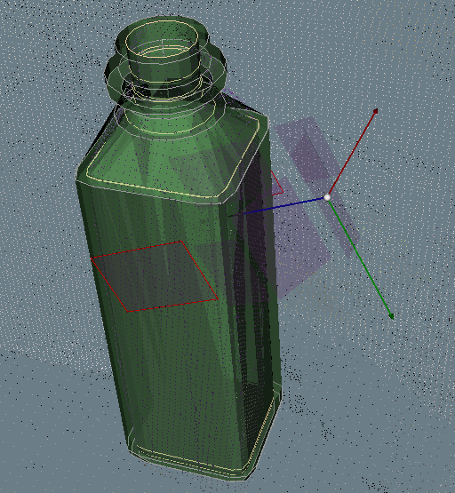
The grasp annotation itself is the 6 DoF pose indicated by the user for the object grasp. An added feature is the inclusion of the pre-grasp, which represents a possible approach vector for the current scenario. This annotation can be saved with respect to the robot or with respect to the object scaffold, depending on the desired scenario. For the first case, we used the point cloud coordinate origin as the robot’s POV, since we wished to localize the scene with respect to a head-mounted Kinect Sensor. For the second case, the origin of the scaffold was set to the center of the first slice defining the object scaffold, (the base slice). Figure 6 shows a grasp indication using PCP.
3.4.2. Annotating Rigid Object Handling
The waypoints that indicate motion are stored as 6 DoF poses containing the following sequence: a pre-pose, a grasp-pose, and any number of handling waypoints. The scaffold can be used to easily create a representation of the object for visualizing its manipulation. We use a mechanism where a user can see a ghost version of the object being displaced by the gripper. This allowed users to take the object dimensions into account while displacing it in space.
As mentioned above, these annotations are task dependent, and therefore require a higher level semantic mapping between objects and tasks. While this is beyond the scope of this thesis, a possible implementation could relate object scaffolds through waypoint annotations. As an example: two object scaffolds, a milk carton and a bowl, could be connected through a grasp and waypoint-sequence to indicate the action ”pour”. Although this path would depend on the spatial context, a multitude of these examples would constitute a rich dataset for extracting high-level understanding of the complex “pour” task.
3.5. Experimental Design
There are two important aspects in evaluating the scaffold-based annotation scheme. The first involves measuring the effectiveness of the designed implementation for accomplishing tasks and the ease with which subjects can learn to operate it. The second has to do with analyzing the characteristics of the interaction itself in terms of what users can do well, and what constitutes a limitation for valuable annotation. To obtain metrics for both aspects, the following protocols were designed to contain ways of measuring interaction and annotation quality as well as objective (quantitative) characteristics of the annotation process.
We split the usability study into two main modules: object modeling from point clouds, and pick-and-place. The object pick-and-place module was, itself, divided into two separate tasks: grasping of objects, and handling of gripped objects in space. In order to evaluate the interface’s precision and ease of use, we compare it to alternative software and interaction schemes that might serve as a “gold standard”.
We made a separate user study (with different sets of users) for each of the following experiments:
-
•
PCP Object Modeling Experiment, where subjects used our interface to construct object scaffolds from pointclouds.
-
•
PR2 Pick-and-Place Experiment, where subjects guided the PR2’s robot arm and gripper through a set of Pick-and-Place tasks, similar to (Balasubramanian et al., 2014).
-
•
PCP Pick-and-Place Experiment, where subjects were asked to complete a set of Pick-and-Place tasks using PCP.
Preliminary Subject Assessment
Every user was asked to complete entry and exit surveys as well as a spatial reasoning evaluation based on the Mental Rotation Test (MRT) (Vandenberg and Kuse, 1978). The entry survey was used to record self reported measures of previous experience with different categories of UIs. The exit survey was used to inquire about perceived effort and difficulty in completing their assigned tasks. The spatial reasoning evaluation is a reduced version of the MRT that contains 12 of the 24 questions. We used the analysis of the (MRT) by Caissie et al (Caissie et al., 2009) to choose the sequence of questions that would maintain the general structure of the test while reducing its duration.
The surveys were self reported values in the range and the spatial reasoning evaluation score, or (SR) was an integer in the range , with being the highest possible score.
Participants
Participants were contacted from within the university through mailing lists and flyers. For the reconstruction experiment we had participants, male, and female, with in the age range and one of ; in the PCP pick-and-place experiment, we had participants, male, and female, with all in the age range; in the PR2 pick-and-place experiment, we had participants, male, and female, with in the age range and two with and years.
3.5.1. User Study: PCP Object Modeling
The high level evaluation approach was to compare the resulting reconstructed shapes obtained from PCP to alternative methods. The alternative methods included an automatic reconstruction method: Kinfu; and different solution based on CAD: Solidworks (sol, 2018).
Experimental Setup (PCP):
Participants use a normal keyboard and mouse setup in front of a screen. They first must complete a tutorial that uses videos and asks them to follow along with PCP. Once they have completed this stage, thy are shown each of the tasks and asked to compete them using PCP. No time constraints were imposed on them. One important aspect of the approach is that users were allowed to see the objects they were supposed to model. This can be justified by the fact that CAD users had access to the original objects and Kinfu is based on a scan of the original objects as well. Users may instead see snapshots of the objects instead of having direct access to them, which would be sufficient to help them counteract the deficiencies present in the scanned clouds.
Protocol:
For reconstruction, subjects were asked to follow a tutorial that would teach them to use PCL. The tutorial lasted between 1 and 2 hours and was designed to illustrate all of the reconstruction features that we wished to evaluate. While this approach does not directly lend itself to the crowdsourcing scenario, it can be greatly simplified and refined for that purpose. The idea of showing the full set of features was intended to allow users to display the action methodologies that best suited them. This would, in turn allow us to better evaluate user capabilities and the program itself.
After the tutorial was completed, subjects were asked to complete two reconstruction stages. In the first, they were given the task of reconstructing four shapes. They were told that they could take up to 40 minutes to complete a shape, and were encouraged to try different approaches and tools. In the second stage, they had up to 20 minutes to reconstruct a different set of four objects. The objective of the two stages was to evaluate any change in object quality due to time restrictions. We also wanted to compare error metrics between stages for a pair of objects of the same category.
Choice of Objects:
The objects were chosen to include shape characteristics that would require the use of different techniques provided by PCP. In recent surveys on the state-of-the art of reconstruction from point clouds, Berger et al (Berger et al., 2014, 2017) observed that the classes of shapes that were reconstructed fell into the following categories:
-
•
CAD models: these refer to assemblies of simple geometric primitives.
-
•
Organic shapes: free-form, often curvilinear structure.
-
•
Synthetic shapes: shapes with canonical geometric properties and regularity.
-
•
Architectural models: A subset of Synthetic shapes, usually contain a great deal of global regularity and functional constraints.
-
•
Urban environments: Large scenarios composed of a limited number of object types. Also contain several functional constraints and regularities.
-
•
Indoor environments: Mixture of Synthetic and organic shapes, also with a reduced number of object types.
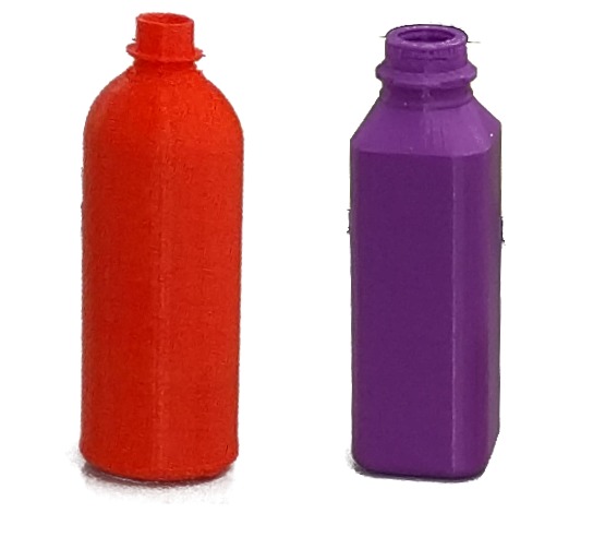
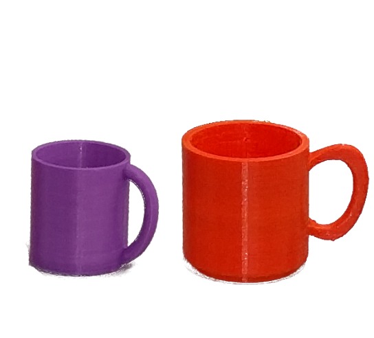
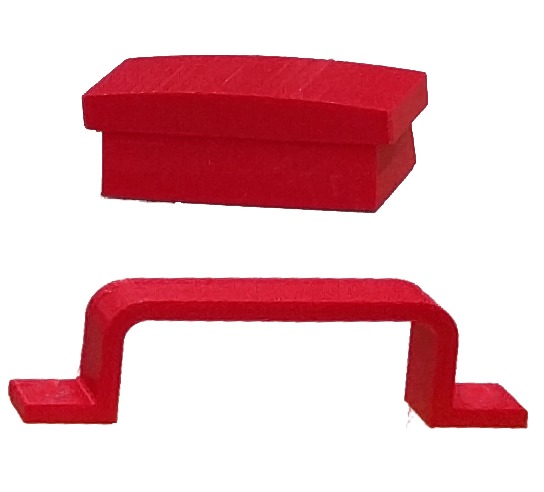
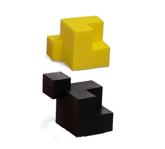
For our study, we wished to represent characteristics from these general classes but also allowing for repetition of object types. We wished to measure variation within classes as well as user progress for the same type of object. The chosen objects and their categories are shown in Figure 7.
Since at the moment, our focus is on robotics for indoor environments, we did not consider architectural models nor outdoor environments. These, however, do not necessarily fall outside the capabilities of PCP. We therefore chose four types of objects where the categories of CAD, Synthetic, Organic, and Indoor would be represented:
- •
-
•
Organic shapes: We used two bottles and two mugs. While the bottles had more regular curvilinear parts, the handles on the mugs show more stylized curves and angles (See Figure 7b).
-
•
Synthetic shapes: In addition to the bottles and mugs (which have synthetic qualities), we used a category we called handle. This was represented by a shoe-brush and a handle one could find in a drawer. These two are the most different instances within a category. This is due to the fact that the function they are meant to be used with is different (See Figure 7c ).
-
•
CAD model: We used the cuboid class, represented by two objects composed of the boolean operation of three cubes in two different ways (See Figure 7d ).
We used the same four types of objects in two separate reconstruction stages. This was done so to measure user progress within the same shape category. In addition to the shape categories, the instances themselves had important characteristics. The bottles had several small details that were below the Kinect’s resolution of . The mugs had the added difficulty of representing a different topology (toroidal). The handles, were of different types: with one being the top part of a shoe-brush and the other being a handle similar to the ones used in briefcases. The cuboids, while simple, offered the widest range of construction approaches and were not an object that would be familiar to the subjects. In addition to their shape characteristics, these objects were chosen for the different grasps they might afford.
Since we wanted to have a ground-truth for the dimensions of the objects, we had them 3D-printed from ideal meshes. These 3D-printed objects were then carefully scanned using PCL’s Kinfu algorithm to generate the base point clouds that PCP users would work on. In addition to the base point clouds, the mesh output of Kinfu was carefully segmented (to isolate the target shapes) and post-processed to generate a proper watertight model (necessary for extracting some integral properties). These were later used to compare the results of PCP.
In preliminary tests on the point cloud editing capabilities we found that point cloud editing actions did not constitute a major time sink (less than one minute). We therefore pre-segmented the objects from the scene so that subjects could focus on reconstruction routines and not point cloud editing.
For the Solidworks meshes, candidates with experience using the software were asked to first measure, and then design the objects following the same two stages. They, however were allowed to take as much time as necessary to measure the objects. They were also allowed to take as many pictures of the objects as necessary to have a good idea of the shape when they attempted to design the objects.
Metrics:
During reconstruction, an action log was recorded for all users. In addition, notes were compiled on reported difficulties and user interactions. These were used to obtain number and distribution of actions as well as duration information for every session. This in turn was used to obtain metrics for the effort required to complete each shape.
For the quantitative analysis of shape quality, we used several shape characteristics obtained from the resulting scaffold-generated meshes. We used the work of Brian Mirtich (Mirtich, 1996) to compute integral properties from the generated polyhedral masses. These included Center Of Mass (COM), surface, volume, and the distribution of point-masses around the volume, as represented by the object’s Inertial Tensor (IT). We compared these with those obtained from the original “ideal” meshes. The direct error metrics were:
-
•
COM Error:
-
•
Surface Error:
-
•
Volume Error:
-
•
Inertia Tensor Error:
where:
-
-
is the euclidean distance.
-
-
is the norm.
One additional metric is the Hausdorff Distance (HD), which is a popular method of measuring distance between point sets. It is the greatest of all the distances from a point in one set to the closest point in the other set.
While useful, this metric is very sensitive to outliers and holes. We therefore used the Mean Hausdorff Distance (meanHD) or (Ćurić et al., 2014):
These measurements can help indicate the size and direction of error. The volume, for example, can be underestimated or overestimated, which is why observing the sign of the results is important. One problem with these measurements is that every object would contain errors at different scales, and therefore would not allow their proper comparison. This is why we obtained a second level of measurements that scaled each metric according to the appropriate characteristic in the ideal meshes. The normalized metrics were:
-
•
relative COM Error:
-
•
relative Surface Error:
-
•
relative Volume Error:
-
•
relative Inertia Tensor Error:
-
•
relative mean Hausdorff Distance:
where:
-
-
is the absolute value
-
-
is the length of the ideal object’s bounding box diagonal.
-
-
relative Volume Error:
-
-
is the maximum eigenvalue in the ideal inertia tensor. This represents the largest wrench that can be applied when the is aligned with the world axes.
3.5.2. User Study: PCP Pick-and-Place
In a way similar to the one used for reconstruction, we devised a protocol that would allow the recording of qualitative and quantitative measurements of the interaction. The objective was to evaluate if the minimal GUI was sufficient to indicate different grasps. In addition, we wished to see what aspects of the task were difficult for humans to deal with and which were easy. To accomplish this, we gathered grasping annotations with PCP and evaluated them using the PR2. In addition, as a comparison interaction scheme, we had subjects physically guide the PR2 arm and gripper to accomplish the same tasks, in a manner similar to (Balasubramanian et al., 2014). In this study it was reported that human guidance was superior to automatic grasping when considering real grasping situations and the larger context of the grasp with respect to the task. For both approaches, we recorded te PR2 end-effector poses throughout the indicated trajectories, from which we were able to extract measurements to compare both approaches. We also recorded video of the live-manipulation so that we could evaluate the quality of the interaction. The protocol for the live-guidance tests is explained in 3.5.3.
Experimental Setup (PCP):
Participants use a normal keyboard and mouse setup in front of a screen. They first must complete a tutorial that uses videos and asks them to follow along with PCP. Once they have completed this stage, thy are shown each of the tasks and asked to compete them using PCP. No time constraints were imposed on them.
Protocol (PCP):
For handling, subjects were asked to follow a tutorial that would teach them to use PCP. The tutorial lasted between 20 and 30 minutes and was designed to show the features that would allow users to record waypoints for grasping and object ghost manipulation. The same way as above, this module could be easily adapted for use in crowdsourcing.
After the tutorial, subjects were asked to complete manipulation challenges in a virtual setting. The scenario was obtained in the following way: A PR2 robot is placed in front of a table that has some objects placed on its surface. This scenario was captured using PCL’s Kinfu and visualized in PCP. Then, subjects were asked to complete a series of manipulation challenges. The challenges were divided into three stages. In the first, they were asked to record a grasp position followed by a waypoint sequence to place an object in a box in one configuration. The second staged asked the same, but with the box placed in a different configuration. In the third, thew were shown a video of specific manipulations (done with the PR2), with their objective being to replicate the sequence as closely as possible.
The first and second stages included all eight objects described above, and a box that can be placed with its opening facing forward (vertical box), like a cubby in a bookcase; or facing upward (horizontal box), like a drawer. Figure 8 shows the positions of the objects for the vertical challenges.
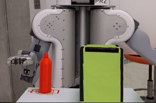
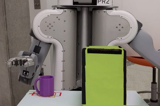
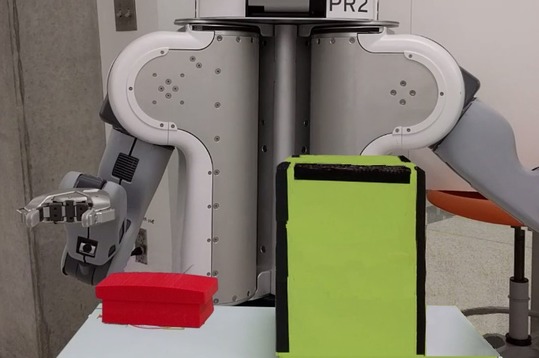
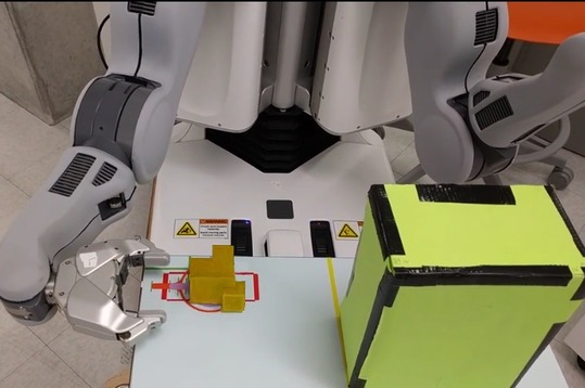
Figure 9 shows the positions of the objects for the horizontal challenges.
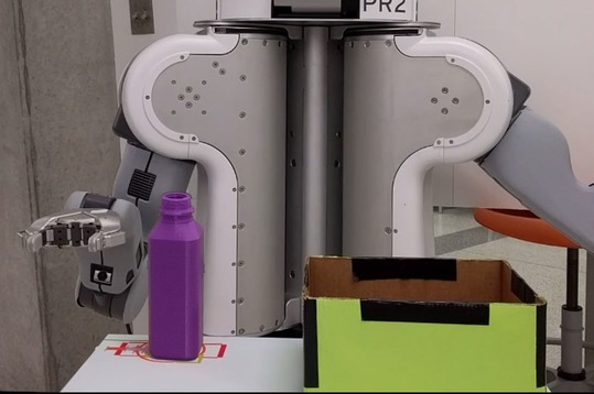
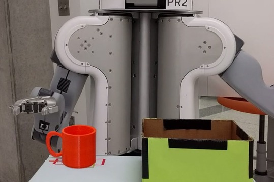
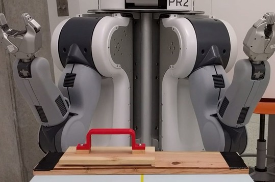

Stages and one had the following challenges:
-
•
Bottle 1 had to be picked up and placed in the vertical box. See Figure 8a.
-
•
Mug 1 had to be picked up and placed in the vertical box. See Figure 8b.
-
•
Handle 1 (brush) had to be picked up used to “clean” the near side of the vertical box.See Figure 8c.
-
•
Cuboid 1 had to be picked up and placed in the vertical box. See Figure 8d.
-
•
Bottle 2 had to be picked up and placed in the horizontal box. See Figure 9a.
-
•
Mug 2 had to be picked up and placed in the horizontal box. See Figure 9b.
-
•
Handle 2 had to be grabbed and pulled to rotate a board attached to the table with a hinge. See Figure 9c.
-
•
Cuboid 2 had to be picked up and placed in the horizontal box. See Figure 9d.
The handle challenges were the most specific in terms of functional requirements, while the others just needed to be completed while avoiding major collisions that would cause the challenge to be considered a failure. The reason for the change in box configuration was to see if users would adapt the grasp positions to the new tasks. When assigning the tasks, we always specified the conditions for success: The grasp had to succeed, the trajectory had to avoid collisions and remain within reach of the robot, and the objects had to be handled in a way that did not conflict with any conditions we attached to the task. We called these functional objectives For example, all bottles and mugs were to be handled as if they were carrying water; the brush had to touch the box surface and complete a full sweep of its side; and the rotating board had to rotate along its proper mechanical axis of rotation.
For the third stage, the challenges were the following:
-
•
Bottle 1 had to be picked up from the top and placed in the horizontal box.
-
•
Mug 1 had to be picked up from the top and placed in the horizontal box.
-
•
Handle 2 had to be grabbed up from the top and pulled to rotate a board attached to the table with a hinge.
-
•
Cuboid 2 had to be picked up from the side and placed in the vertical box.
These challenges were added to measure the precision of waypoint positioning. These also serve as a way to see what aspects of the interaction are difficult for humans to replicate using a GUI as compared to live manipulation. Figure 10 shows the setup for these challenges.
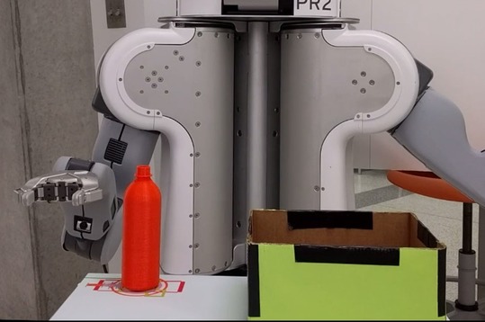
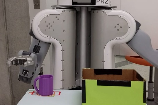
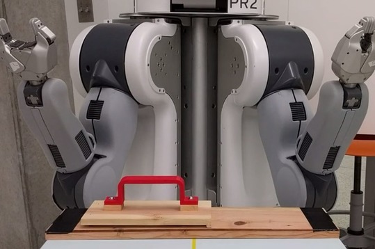
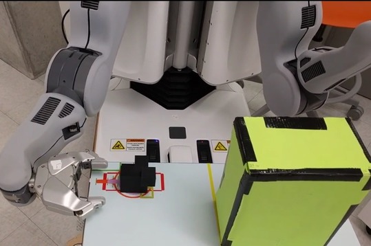
Metrics (PCP):
We recorded actions and timing in a log during the motion annotation. We also evaluated each grasp and manipulation qualitatively, recording a variety of interaction features that could help characterize the quality of the manipulation.
To validate the manipulation annotations, we used the MoveIt package in ROS (Sucan and Chitta, 2013) to follow the set of indicated waypoints. No additional collision avoidance mechanisms were used so that all user-indicated paths with minor or major collisions could be observed and graded. The following are scales used for classifying the interaction quality.
Grasping:
We divided the qualitative analysis of the grasps into pure grasp quality and functional quality. Pure grasp quality evaluates the grasp by itself, and whether or not it can hold the object independent of the handling task. The scaling for pure grasp quality is:
-
(1)
Miss: the object is missed completely by the PR2.
-
(2)
Slip: the object is nudged or loosely grasped and dropped at some point.
-
(3)
Shift: the grasp has minor flaws but holds.
-
(4)
Good: the object is firmly grasped.
Functional quality looks at whether or not the grasp would allow the proper completion of the task independent of the path used to do so. As an example think of a mug held by the top. If the objective is to pour, then the grasp would receive a good pure grasp quality but a flawed or impossible functional quality, since the top grasp would make the pouring difficult or impossible. For this evaluation, the scales are the following:
-
(1)
Impossible: the grasp would prevent the completion of the task.
-
(2)
Flawed: the grasp has minor flaws but can allow the completion of the task.
-
(3)
Good: the grasped is adequate for the task.
For the quantitative analysis of grasp quality, we used the metrics provided by GraspIt: the volume of the Grasp Wrench Space and the radius of the largest inscribed sphere, also called the epsilon-distance. GraspIt has the capacity to verify grasps under dynamic settings, allowing the objects and grippers to shift into stable grasps.
Force-Closure is a grasp that can resist disturbance forces from any direction, given sufficiently large contact forces. We considered grasps with force closure under dynamic settings as successful grasps.
Handling:
For the Pick-and-Place manipulation as a whole, we looked at three different handling characteristics: collisions, robot configuration problems, and object handling flaws.
Collisions:
-
(1)
Major: the gripper hits the table, object, or box in a way that makes the challenge fail.
-
(2)
Minor: the gripper nudges the object or table mildly, in a way that does not preclude success.
-
(3)
Free: no collisions.
Robot configuration problems:
-
(1)
Fail: for most or crucial parts of the path, the robot would hit itself or attempts to move beyond its reach.
-
(2)
Partial: at a single uncritical part of the path, the robot would hit itself or attempts to move beyond its reach.
-
(3)
Good: no problems with self collisions or reach.
Object handling flaws:
-
(1)
Bad: for most or crucial parts of the path, handling of the object invalidates the functional objectives.
-
(2)
Fair: at a single uncritical part of the path, object is mildly mishandled.
-
(3)
Good: no problems with object handling.
The combination of the above three requirements would determine the result of the overall object manipulation challenge (discounting grasping). Path quality had the following scale:
Path quality:
-
(1)
Impossible: the task cannot be completed with the specified path.
-
(2)
Flawed: parts of the annotation cause the path to be executed imperfectly.
-
(3)
Good: path is adequate for the task.
Finally, the whole task, including grasping and path handling were combined to evaluate the quality of the challenge as a whole.
Challenge quality:
-
(1)
Fail: the challenge cannot be completed with the specified path or grasp.
-
(2)
Partial: parts of the annotation cause the challenge to be executed imperfectly.
-
(3)
Good: the path and grasp are adequate for completing the challenge.
-
(4)
Perfect: The challenge is completed with no flaws.
In addition to these manipulation characteristics we extracted the total distance of the chosen manipulation. Also, for the replication challenges, we developed a path comparison metric that we called ribbon area.
The ribbon area:
path error was defined as the line integral of the distance function between the two paths. In practice, and since we are using discrete waypoints, we simplified this to simply add the area generated between subsequent pairs of points at equivalent positions along the paths. his area becomes zero for identical paths, and grows as the distance between equivalent points increases. Figure 11a shows the concept; Figure 11b shows the implementation using Matlab;
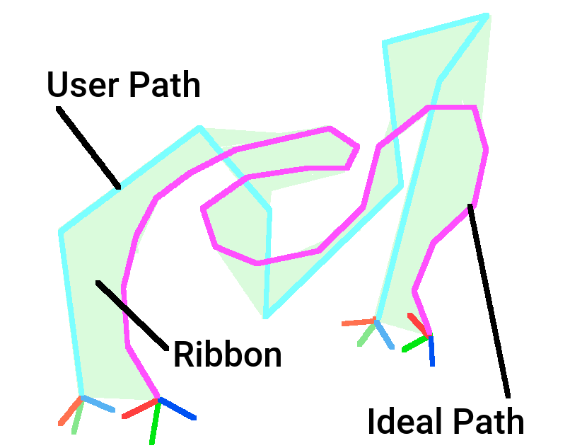
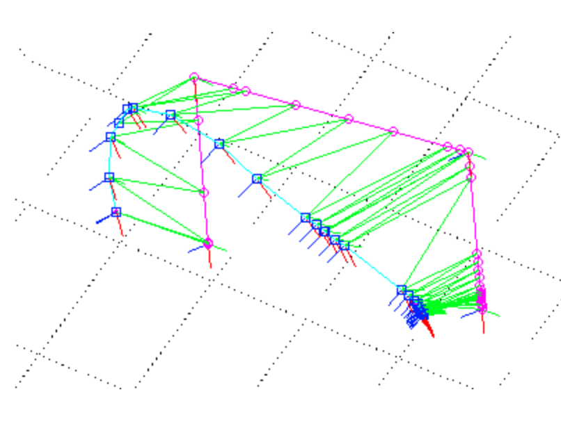
3.5.3. User Study: PR2 Rigid Object Handling
Experimental Setup (PR2):
Figure 12 shows the PR2 handling setup, and Figures 8, 9, and 10, are the (same) setups for the PR2 challenges. The PR2 was always positioned in a pre-defined initial configuration to maximize its reach. The table in front of it was fixed in relation to the robot using a harness to prevent the variation in the relations between parts. Objects were placed in the same locations, guided by their projected positions on the worktable.
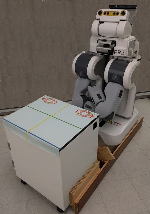
Protocol (PR2):
For handling, subjects were shown how to move one arm of the PR2 robot (the same as their dominant hand). The tutorial lasted between 5 and 10 minutes and was designed to familiarize the subject with the ways in which the robot could move. While the PR2 robot has a similar general structure to that of a person, the PR2 arm joints have slightly different motion capabilities that human arms i.e. some joints, like the wrist or the shoulder are composed of two independent revolute joints.
Subjects were instructed to complete the same 12 challenges as the ones described above. The sequence of actions was the following:
-
(1)
The subject had to move the arm from an initial position to a grasp position of their choice.
-
(2)
When ready, they would instruct the PR2 operator to close the gripper.
-
(3)
The subject would then move the arm and the held object in a path that would complete a challenge.
-
(4)
When done, the subject would ask the PR2 operator to open the gripper.
-
(5)
After releasing, they would return the arm to the initial position.
Metrics (PR2):
We used the same quality scoring system as the one specified above. Since we saved the end-effector path as sequences of poses, we were able to convert the physical motion to a sequence of waypoints that could be directly compared to the PCP manipulation experiments.
3.6. Data Analysis
3.6.1. Reconstruction Statistics
The experimental design is for independent measures with many groups. As will be explained in the Results section, the error values did not have a normal distribution. We therefore used the non-parametric Kruskal-Wallis test (Hollander et al., 1973) to verify if the population distributions for all approaches were identical. If a difference was found, pairwise Mann-Whitney-Wilcoxon Test (Bauer, 1972) with Bonferroni correction (Dunn, 1958) was employed to see if pairs of approaches could be considered statistically identical or not.
For the case of analyzing interactions between variables, we fitted a linear model to complete a regression analysis between pairs of variables. We used the Shapiro-Wilk normality test to verify that the regression residuals are well behaved and no important variables are missing.
3.6.2. Handling Statistics
This analysis applied to both the PCP and PR2 handling modules. The experimental design is for independent measures with many groups. Here, we used frequencies to record successes over failures for each challenge. We therefore used the Chi-squared test of independence to verify if the population distributions for all approaches were identical. If a difference was found, post-hoc pairwise Chi-squared tests with Bonferroni correction were performed.
For the grasp objective metrics, we used the non-parametric Kruskal-Wallis test to verify if the population distributions for all approaches were identical. If a difference was found, the pairwise Mann-Whitney-Wilcoxon Test with Bonferroni correction was employed to see if pairs of approaches could be considered statistically identical or not.
For the case of analyzing interactions between variables, we fitted a linear model to complete a regression analysis between pairs of variables. We used the Shapiro-Wilk normality test to verify that the regression residuals are well behaved and no important variables are missing.
4. Results
This section details the results of the qualitative and quantitative analysis of four tasks: reconstruction, grasping, and Pick-and-Place.
4.1. Reconstruction Results
4.1.1. Competing Methods
-
•
PCP : These are novice users of PCP.
-
•
PCP Expert : This is an expert user of PCP.
-
•
CAD : These are experienced Solidworks users.
-
•
Kinfu : This is PCL’s version of the Kinect Fusion automatic reconstruction algorithm.
For PCP, the total number of participants to complete the minimum number of shapes () was . A total of novice user shapes were created, and since we used relative error metrics, we were able to integrates measurements from all the different shapes. For cad, subjects provided shapes. They were selected from students that had completed a CAD modeling class using Solidworks, and ranged in experience from to hours. A total of CAD user shapes were created. Again, the use of relative error metrics allowed us to integrates measurements from all the different shapes. The last shapes we evaluated were the mean shapes for each object. We obtained a total of mean shapes, each of which required an average of novice meshes (since not all shapes were completed by all subjects).
4.1.2. Qualitative Analysis of Shapes
While subjective, visual inspection of the constructed shapes revealed several interesting features. Figure 13 shows examples of reconstructed shapes for all approaches. Figure 13a shows the result of stage , and 13b shows the result of stage . In the images, the column under the black dot is the original object; the light blue column represents examples of good and bad novice user reconstructions; the dark blue dot is for the PCP expert shapes; the pink dot is for the Solidworks users; and the green one is the Kinfu reconstruction.
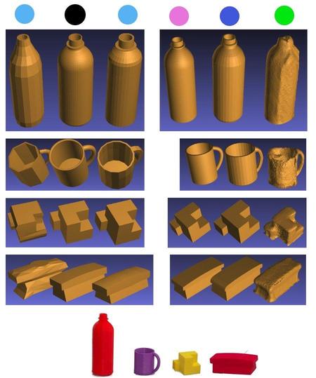
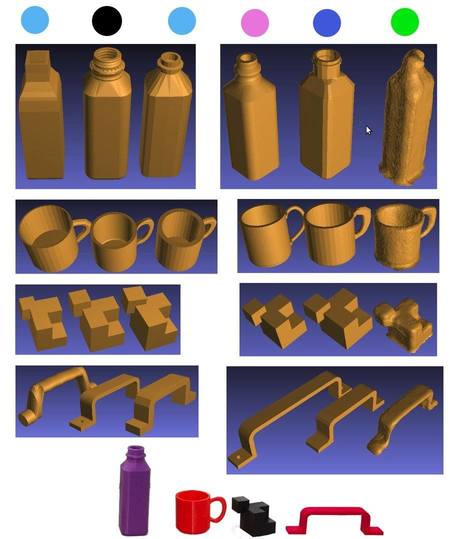
Kinfu:
First, the obvious problem with Kinfu has to do with the aforementioned issues with thin surfaces, occlusions, and sensitivity to scan smoothness. The Kinfu scans tends to underestimate the external volume of shapes, which, in turn, affects the modeling on PCP, which uses the Kinfu-generated pointclouds as the basis of the scaffold placement. On the other hand, Kinfu does not have the ability to record internal structures or hard-to-see cavities, which means that it would consider those areas as “occupied”, and therefore as extra positive volume. As a result, shapes with cavities like the bottles and mugs are overestimated in terms of overall volume, while shapes without cavities are underestimated in volume.
Solidworks:
These were expected to be the most accurate shapes, but, even though they are in general, one bad measurement can result in large errors in the resulting shape.
PCP novices:
The initial shapes vary greatly in quality for the first set of four, but become less varied for the final four shapes. The greatest errors occur for the initial shapes, like erroneous hole specification, or problems with the generation of some object’s part.
PCP mean shapes:
The quality of the resulting shapes was quite surprising. The shapes can be seen in Figure 14 next to the original objects. While the novice pcp shapes contained outliers with large errors, the mean shapes contain more similar appearances than the individual novice reconstructions. Locations where multiple individual shapes “agree” on shape are reinforced and are therefore maintained in the resulting mean shape, causing outliers to be dismissed.
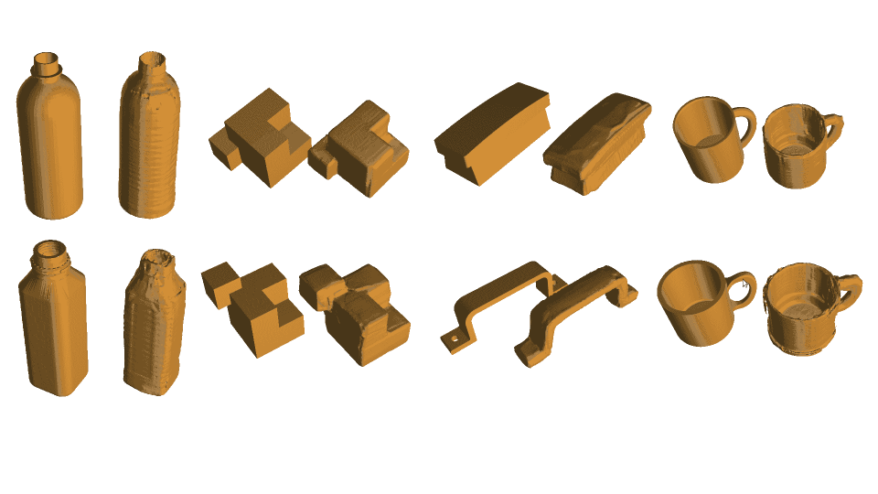
4.1.3. Quantitative Analysis of Shapes
The following are the results from comparing the shape measurements. As mentioned before, we used the relative metrics to be able to compare the different shapes. These do not follow normal distributions, and therefore had to be analyzed using a non-parametric test. We used the Kruskal-Wallis test to determine if the population distributions were identical. If they were not, a pairwise Wilcox test with Bonfernoni correction was used to determine which pairs of treatments were statistically different.
In the following, CAD represents the results from the Solidworks shapes; Kinfu for the automatic reconstruction; PCP for the novice PCP users; is for the PCP expert; and for the PCP mean shapes. The first thing we evaluated was the difference in modeling times for the Human-In-the-Loop approaches: CAD, PCP, and PCP expert.
Full Modeling Time:
We found a significant difference in modeling times (, ). Table 1 shows the result of applying the pairwise Wilcox test with Bonferroni correction .
| CAD | PCP | |
|---|---|---|
| PCP | 1.000 | - |
| ¡0.05 | ¡0.01 |
As can be seen from the table and Figure 15, PCP and CAD users took about the same time to make the shapes, while the PCP expert took less time. This result was somewhat influenced by the modeling protocol, where we indicated time limits for each modeling session.
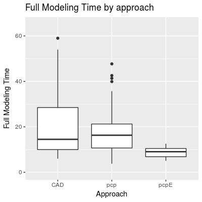
As can be seen in Figure 16, modeling times were more variable in the first section, which points to a rapid homogenization after only four modeling tasks.
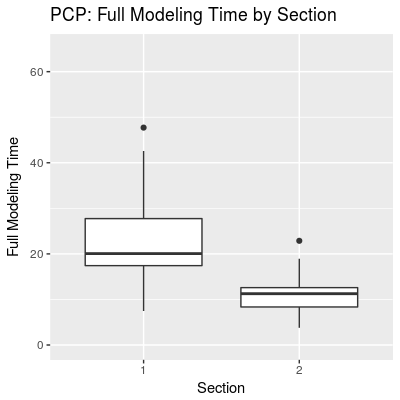
Error Metrics:
The next section show the differences for each error metric.
Center of Mass:
We found a significant difference in COM errors (, ). Table 2 shows the result of applying the pairwise Wilcox test with Bonferroni correction .
| CAD | kinfu | PCP | ||
|---|---|---|---|---|
| Kinfu | 0.240 | - | - | - |
| PCP | ¡0.0001 | 1.000 | - | - |
| 1.000 | 1.000 | 0.078 | - | |
| PCP | 1.000 | 1.000 | 0.216 | 1.000 |
This, together with the box plots shown in Figure 17, indicates that the PCP expert and PCP had a similar error than CAD,and while Kinfu and PCP novices fared a bit worse, they had small and similar error sizes among themselves.
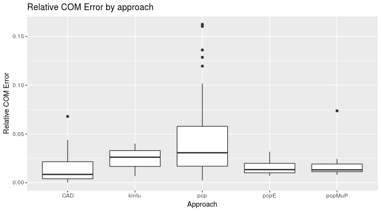
Surface:
We found a significant difference in surface errors (, ). Table 3 shows the result of applying the pairwise Wilcox test with Bonferroni correction.
| CAD | kinfu | PCP | ||
|---|---|---|---|---|
| Kinfu | ¡0.05 | - | - | - |
| PCP | ¡0.05 | 0.231 | - | - |
| 1.000 | ¡0.05 | 0.418 | - | |
| PCP | 0.888 | 0.148 | 1.000 | 1.000 |
This, together with the box plots shown in Figure 18, again indicates that the PCP expert and PCP had a similar error than CAD. Kinfu and PCP novices also had small and similar error sizes.
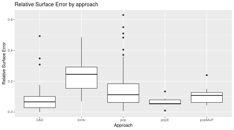
Volume:
We found a significant difference in volume errors (, ). Table 4 shows the result of applying the pairwise Wilcox test with Bonferroni correction .
| CAD | kinfu | PCP | ||
|---|---|---|---|---|
| Kinfu | 0.1050 | - | - | - |
| PCP | ¡0.01 | 1.0000 | - | - |
| 1.0000 | 0.3792 | 0.7509 | - | |
| PCP | 1.0000 | 1.0000 | 1.0000 | 1.000 |
This, together with the box plots shown in Figure 19, again indicates that the PCP expert and PCP had a similar error than CAD. Kinfu and PCP novices also did a bit worse and had small and similar error sizes.
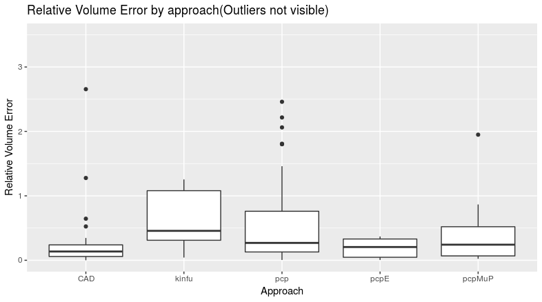
Inertia Tensor:
We found no significant difference in IT errors.
The relative Inertia tensor errors shown in Figure 20 show that the error distributions were similar. One thing to note is that the smallest variation in error was for the PCP expert, which indicates consistency. The variabilities for novice PCP users and CAD users were similar.
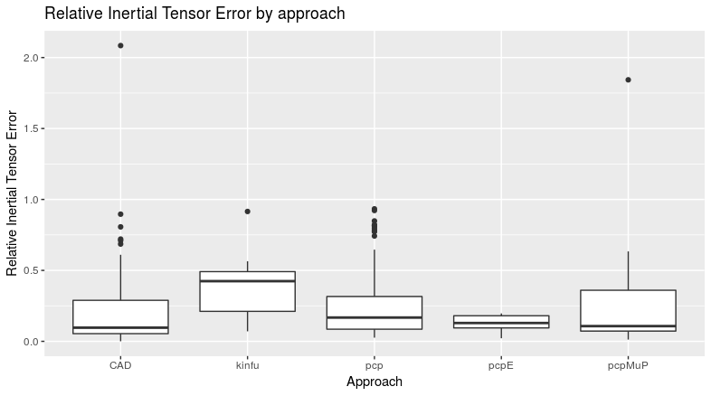
Hausdorff Distance:
We found a significant difference in meanHD errors (, ). Table 5 shows the result of applying the pairwise Wilcox test with Bonferroni correction .
| CAD | kinfu | PCP | ||
|---|---|---|---|---|
| Kinfu | ¡0.05 | - | - | - |
| PCP | ¡0.0001 | 1.000 | - | - |
| 1.0000 | ¡0.05 | ¡0.05 | - | |
| PCP | 1.0000 | 0.006 | 0.0731 | 1.000 |
The above table and the box plots from Figure 21 show that the error distributions for CAD, PCP users, and PCP were similar. Kinfu and PCP novices also did a bit worse and had small and similar error sizes.
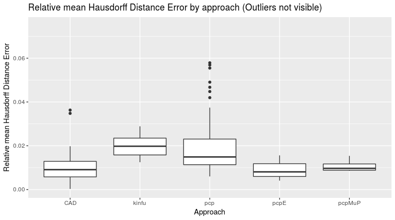
Interesting general observations to note are that novice PCP users consistently matched or outperformed the automatic method in terms of quality, while the PCP expert proved consistently superior. The PCP expert as well as PCP attained a level of precision as good as the CAD users, with the PCP expert times being much shorter than those of CAD. This highlights the surprising and promising approach of merging reconstructions to obtain better prototype objects. The above results hint at the possibility of a rapid increase in precision for new users.
Efficiency:
Since we have duration information and precision errors, we devised a modeling efficiency measurements based on the Hausdorff Distance error metric, which we defined as:
where represents each of the relative error ratios for COM, surface, etc.
Efficiency with respect to the Hausdorff Distance error metric:
| CAD | PCP | |
|---|---|---|
| PCP | 1.000 | - |
| ¡0.05 | ¡0.01 |
The above table and Figure 22 show that novice PCP and CAD users obtain similar efficiency, while the PCP expert surpass both.
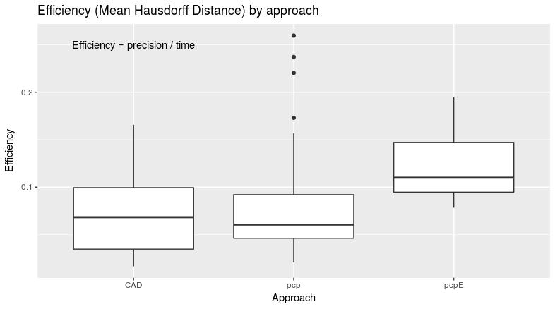
Learning Effort:
The above results show that annotation through PCP has a lot of promise in terms of efficiency and precision. Another important factor is the effort put into learning the software. While no CAD user had less than a minimum of hours of training(self reported), PCP users had only a 2 hour tutorial. Given the similar accuracy results, this hints at a low learning curve for PCP.
Quality by section:
For novice PCP only, we evaluated the overall shape quality, as indicated by the Hausdorff Distance for each of the two stages. The box plots in Figure 23 reveals that the errors had the same distribution (no significant difference) despite the accelerated time requirements for the second section. This supports the idea of a low learning curve and that users may attain good precision quickly.
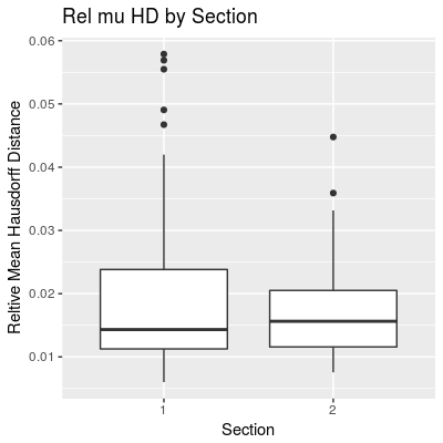
Measured interactions:
In addition to shape characteristics, we analyzed possible interactions between these and the user’s spatial reasoning score (SR). No correlation was found between SR and COM or Surface errors. However, we found medium to large effects for Volume, IT, Hausdorff Distance, and modeling duration. These confirm the assumption that subjects with higher spatial reasoning abilities obtain better results due to their increased understanding of shape in 3D.
Relative Volume error vs SR:
Figure 24 shows the results of the linear regression where we found a medium effect size (SQ explains of variation in relative volume error), , , .
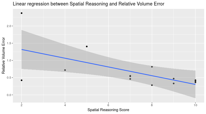
Relative IT error vs SR:
Figure 25 shows the results of the linear regression where we found a small-to-medium effect size (SQ explains of variation in relative Inertia Tensor error), , , .
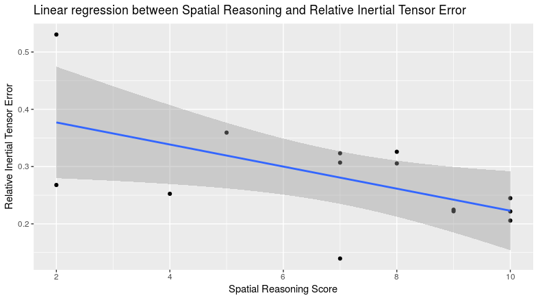
Relative HD error vs SR:
Figure 26 shows the results of the linear regression where we found a large effect size (SQ explains of variation in relative Hausdorff Distance error), , , .
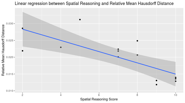
Modeling Duration vs SR:
Figure 27 shows the results of the linear regression where we found a small-to-medium effect size (SQ explains of variation in relative Hausdorff Distance error), , , .
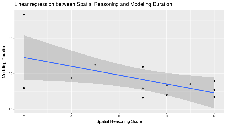
Number of Modeling Actions vs SR:
No correlation was found between SR and the number of actions a user employed for modeling.
4.2. Grasping Results
The approaches considered were PCP, GraspIt!, and manual placement using the PR2 robot. For PCP and the PR2, novice users were compared to the expert user(s). For PCP, the total number of participants to complete the minimum number of grasping tasks () was . A total of novice user grasping poses were recorded and compared. For GraspIt!, the Eigengrasp automatic grasping algorithm was used to generate candidate grasps, where we kept the top scoring grasp hypotheses. Since we had grasping challenges, these gave us automatic grasp poses to compare. For the PR2, we had participants, who generated grasps (not all users finished all tasks).
4.2.1. Qualitative Grasp Analysis
The PCP grasp suggestions were evaluated in the PR2 by using MoveIt to place the end-effector in the indicated position, closing the gripper, and then proceeding with the rest of the manipulation. In the case of GraspIt, the top grasp suggestions obtained from Eigengrasp were evaluated using the GWS volume and eps-dist, and were marked as Good if the grasp had force-closure (any valid GWS volume), and Slip otherwise.
Grasp Quality Distribution:
Figure 28 shows the distribution of observed events during a grasp attempt for each of the grasping approaches.
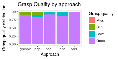
Grasp Success Rate:
Figure 29 shows the distribution of successes vs failures for each of the evaluated approaches. In these, Good or Shift are marked as a Success, and as a Failure otherwise. As can be seen, the majority of actions in every one of the methods result in a grasp that holds the object for a future handling task.
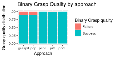
We found a significant difference in grasp success rates (, ). Table 7 shows the result of applying the post-hoc pairwise Chi-squared tests with Bonferroni correction111For some comparisons there was not enough data .
| GRASPIT | PCP | PR2 | ||
| PCP | 1.000 | - | - | - |
| 1.000 | 1.000 | - | - | |
| PR2 | ¡0.01 | ¡0.01 | 1 | - |
| 1.000 | 1.000 | -1 | 1.000 |
What can be seen from the table 7, and Figures 28, and 29, is that PCP users perform as well as GraspIt in terms of success rate. Novice PCP users had a reasonable success rate () with respect to novice PR2 users (). While the PCP and PR2 experts did visibly better than the novice PCP users, they had too few samples to prove a significant difference.
Grasp Quality Distribution:
Figure 30 shows the distribution of observed events with respect to functional quality for each of the grasping approaches.
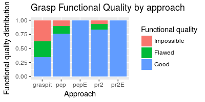
Functional Grasp Success Rate:
Figure 31 shows the distribution of successes vs failures for each of the evaluated approaches with respect to functional quality. In these, Good is marked as a Success, and as a Failure otherwise. As can be seen, the majority of actions in the methods that involve humans result in a grasp that holds the object in a manner that is appropriate for the objective of the task. GraspIt, focusing only on pure grasp quality has no way to take the high level objective into consideration, and therefore obtains a large quantity of inappropriate grasps.
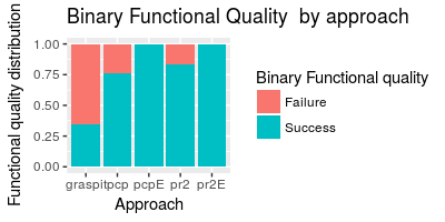
We found a significant difference in functional success rates (, ). Table 8 shows the result of applying the post-hoc pairwise Chi-squared tests with Bonferroni correction.
| GRASPIT | PCP | PR2 | ||
| PCP | ¡0.0001 | - | - | - |
| ¡0.001 | 1.00 | - | - | |
| PR2 | ¡0.0001 | 0.875 | 1 | - |
| ¡0.0001 | 0.147 | -1 | 0.590 |
What can be seen from the table 8, and Figures 30, and 31, is that all approaches that involve humans perform better than GraspIt. PCP and PR2 novice users perform similarly with reasonably high success rates ( and respectively). While the PCP and PR2 experts did visibly better than the novice PCP users, they had too few samples to prove a significant difference. No statistical differences were seen between novices and experts for each approach.
It is important to note that while PCP presents a simplified version of the scene, the distribution of functional quality is very similar to that of the live manipulation scenario. Figure 32 shows the distribution of successes and failures with respect to the tasks.
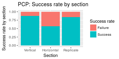
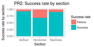
From our observations and user feedback, we noted that a large percentage of users that initially figured out a grasp for the vertical box scenario attempted a similar grasp for the horizontal box scenario without realizing that the same grasp might not be functionally suitable. This problem appeared in both the PCP and PR2 scenarios, where the results from each section were all statistically equivalent.
This, together with the performance of the expert users indicates that PCP was as good as a live grasping in terms of pure and functional grasping success rates.
4.2.2. Quantitative Grasp Analysis
In this section, we analyze the GWS volume and epsilon-distance metrics for each grasp, as well as the time taken to accomplish each task. To do this, we extracted the relative grasp position with respect to each object and exported it to GraspIt. This could be done in the same way in the PCP and PR2 experiments because the pointcloud and object placement was with respect to the exact same coordinate frame: The head-mounted Kinect sensor.
GWS Volume and epsilon-distance:
In Figure 33 shows the GWS volume and -distance metrics for each approach. A statistical difference was found among groups in both the GWS volume (, ) and epsilon-distance (, ) Tables 9 and 10 show the results of applying the pairwise Wilcox test to these groups.
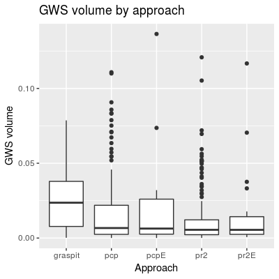
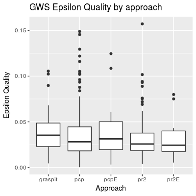
| GRASPIT | PCP | PR2 | ||
| PCP | ¡0.0001 | - | - | - |
| 0.6315 | 1.0000 | - | - | |
| PR2 | ¡0.0001 | 0.8839 | 1 | - |
| 0.0066 | 1.0000 | 1 | 1 |
| GRASPIT | PCP | PR2 | ||
| PCP | 0.369 | - | - | - |
| 1.000 | 1.0000 | - | - | |
| PR2 | ¡0.05 | 1.0000 | 1 | - |
| 0.563 | 1.0000 | 1 | 1 |
Notably, the PCP Expert performed equivalently to the GraspIt Eigengrasp approach for both metrics, and despite being surpassed by GraspIt, novice PCP users achieved equivalent results to all other approaches involving humans.
For PCP, the total number of grasp attempts was , and the number of force-closure grasps was , with a force-closure grasp “success” of . Note that this is not the same as the pure grasp success rate mentioned above () since there are some real grasps that GraspIt evaluates as non-force-closure and some configurations that GraspIt evaluates as valid that in reality slip out of the gripper.
For the PR2, there were grasp attempts with having force-closure. This is also different from the observed pure grasp success rate.
One thing to note is that the magnitudes of both grasp metrics depend on the type of grasp and the robot hand employed. In our case, we have functional-dependent grasps (to complete predefined tasks) and the PR2 parallel gripper (parallel gripper). A multi-fingered robot hand could potentially obtain much higher grasp qualities.
Time:
We compared grasp timing between the approaches that involved humans. The grasp hypothesis generation using the Eigengrasp planner took seconds to obtain the grasp candidates for each case. There are grasp optimization techniques (Ciocarlie et al., 2007) that cause it to take up to seconds, but we did not employ them.
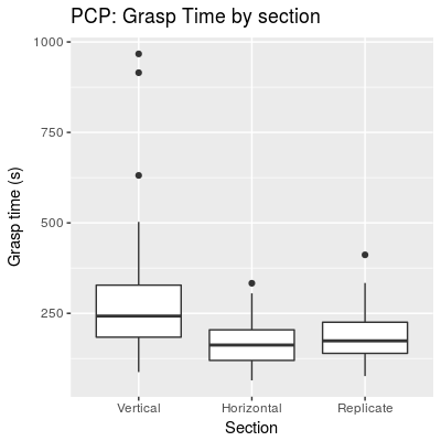
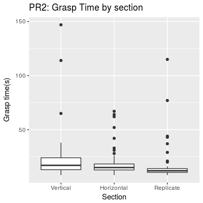
Figure 34 shows the times to complete tasks within each challenge section for each approach. As can be seen in 34a, novice PCP users achieve substantial speedup from the initial section, with seconds, to the last, stabilizing at about an average of seconds, or about minutes. For the PR2, a slightly smaller speedup was noticed: for the first section, it took them an average of seconds, and speeding up to seconds per task for the last section. This points to a rapid increase in abilities under both interaction modes.
For PCP, we found that there was significant difference between sections (, ). Table 11 shows the result of applying the pairwise Wilcox test with Bonferroni correction.
| Vertical | Horizontal | |
|---|---|---|
| Horizontal | ¡0.0001 | - |
| Replicate | ¡0.0001 | 0.32 |
For PR2, we also found a significant difference between sections (, ). Table 12 shows the result of applying the pairwise Wilcox test with Bonferroni correction.
| Vertical | Horizontal | |
|---|---|---|
| Horizontal | 0.18498 | - |
| Replicate | ¡0.0001 | ¡0.001 |
Previous systems that employ assisted grasping have achieved relatively good speeds with respect to automatic grasping (if the time to match is around seconds). In (Weisz et al., 2013), users achieved an averages of between and seconds; in (Hertkorn, 2016) two strategies were employed, obtaining averages of and seconds respectively. We believe that with similar assistance, equivalent speedups can be attained in PCP.
Measured interactions:
In addition to grasp metrics, we analyzed possible interactions between these and the user’s spatial reasoning score (SR). No correlation was found between SR and the GWS volume and epsilon-distance metrics. However, we found medium effects between SR and grasping duration.
Modeling Duration vs SR:
Figure 35 shows the results of the linear regression where we found a medium effect size (SQ explains of variation in grasping modeling time), , , .
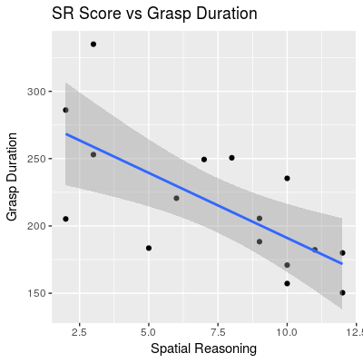
4.3. Pick-and-Place Handling Results
The approaches considered were PCP and manual placement using the PR2 robot. Novice users were compared to the expert user(s). For PCP, the total number of participants to complete the minimum number of handling tasks () was . Since we used the same group of people to do the grasp and handling tasks, we only analyze those paths that achieved a successful grasp on the object. A total of novice user handling paths were recorded and compared. For the PR2, we had participants, who generated handling paths (not all users finished all tasks).
4.3.1. Qualitative Handling Analysis
The PCP handling suggestions were evaluated in the PR2 by using MoveIt to place the end-effector in the indicated pre-grasp waypoint, closing the gripper, and then proceeding with the rest of the handling waypoints. As mentioned above, to evaluate the overall handling path quality (independent of grasping), we looked at three different handling characteristics: collisions, robot configuration problems, and object handling flaws.
Collisions:
Figure 36 shows the distribution of observed collision events during a handling attempt for each approach.
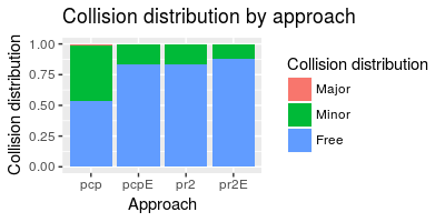
Minor collisions include bumping the object with the gripper before grabbing it, and brushing the table or box with the gripper or held object. Major collisions included hitting the object (preventing its grasping), or hitting the table or box with gripper or bottle. These last impacts happen when waypoints cause the gripper or held object to attempt to go through the table or box.
To run a Chi-Squared test with success frequencies, we considered major collisions as failures and successes otherwise. No significant differences were found between approaches.
Robot Configuration:
Figure 37 shows the distribution of observed robot configuration errors during a handling attempt for each approach.
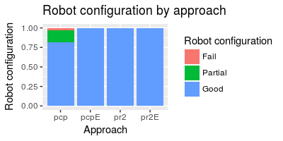
Partial robot configuration errors cause a single non-crucial waypoint to be skipped because the path would cause a self-collision, or would take some part of the arm out of reach. Fails cause several waypoints or a few crucial ones to be skipped for the same reasons.
To run a Chi-Squared test with success frequencies, we considered partial and good configurations as successes, and failures otherwise. No significant differences were found between approaches.
Object Configuration:
Figure 38 shows the distribution of observed object configuration errors during a handling attempt for each approach.
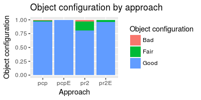
Fair object configuration errors mean that the object was slightly mishandled. Bad object configurations happen when objects are grossly mishandled in at least one point.
To run a Chi-Squared test with success frequencies, we considered fair and good configurations as successes, and failures otherwise. No significant differences were found between approaches.
Overall Handling Quality:
Figure 39 shows the distribution of observed events during a handling attempt for each approach.
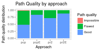
Flawed overall quality meant that any part of the handling task had a flaw that would not prevent the task from being completed. Attempts counted as impossible would not allow the completion of the task, even with a perfect grasp choice.
To run a Chi-Squared test with success frequencies, we considered Flawed and Good attempts as successes, and failures otherwise. No significant differences were found between approaches.
4.3.2. Quantitative Grasp Analysis
In this section, we analyze the time and path-distance metrics for each handling, as well as the time taken to accomplish each task. To do this, we extracted the relative waypoint positions with respect to the exact same coordinate frame: The head-mounted Kinect sensor.
Handling Time:
The PR2 users were, as expected, faster than those using PCP. We mainly wanted to see how novice and expert users compared under the two approaches, and how PCP users did in comparison to other interface options. Figure 40 shows the distribution of observed handling times for each approach. Novice PCP users averaged manipulations in seconds, or about minutes, while the expert took an average of seconds, or about minutes. For the PR2, novice users averaged seconds, with seconds for the experts.
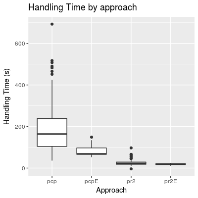
A more detailed view of the handling times can be seen in Figure 41. As can be seen in 41a, novice PCP users achieve substantial speedup from the initial section, with seconds, to the last, stabilizing at about an average of seconds, or about minutes. For the PR2, a similar speedup was noticed: for the first section, it took them an average of seconds, and speeding up to seconds per task for the last section. This points to a rapid increase in abilities under both interaction modes.
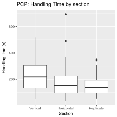
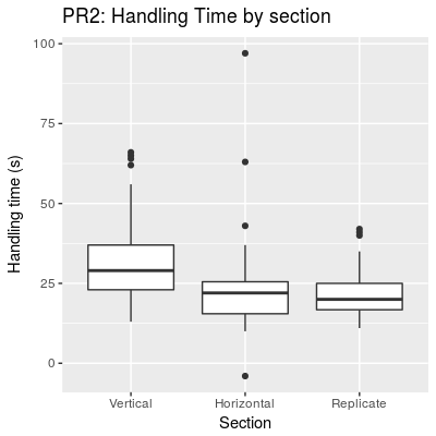
For PCP, we found that there was significant difference between sections (, ). Table 13 shows the result of applying the pairwise Wilcox test with Bonferroni correction.
| Vertical | Horizontal | |
|---|---|---|
| Horizontal | 0.0870 | - |
| Replicate | ¡0.05 | 1.0000 |
For PR2, we also found a significant difference between sections (, ). Table 14 shows the result of applying the pairwise Wilcox test with Bonferroni correction.
| Vertical | Horizontal | |
|---|---|---|
| Horizontal | ¡0.001 | - |
| Replicate | ¡0.001 | 1 |
These results indicate that users quickly gain proficiency while maintaining or improving the precision (see path results above).
Handling Path Distance:
the absolute magnitude of a handling path distances might not mean anything by itself, since tasks were different and - for the non-replication tasks - styles varied. We did, however compare path distances between approaches to see if the interface altered this characteristic. It did not.
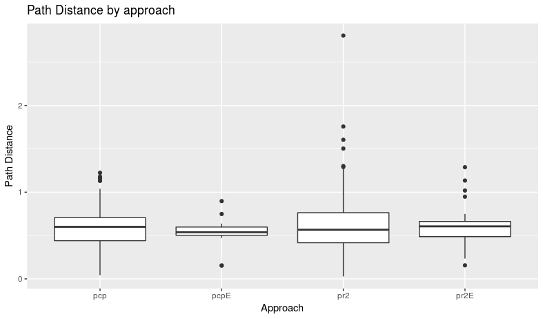
Figure 42 shows the different path distances for each approach. No significant difference between approaches was found.
Figure 43 shows the distances for each shape per approach for the vertical and horizontal box challenges. Figure 44 shows the respective distances for the replication challenges. As can be seen, both approaches have very similar results.
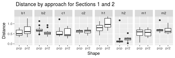
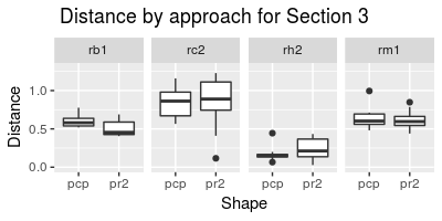
Difference between paths (Ribbon Area):
For the replication challenges, we evaluated the precision with which subjects copied the indicated paths. The ribbon area is the approximate area of the accumulated linear error between the ideal path (the one we prerecorded and showed to subjects for replicating) and the subject-provided one.
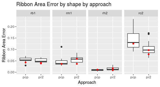
Figure 45 shows the ribbon area error for each shape per approach for the replication challenge. The red dots show the respective errors obtained by the experts. As can be seen, both approaches have very similar results. For the cases of the bottle and mug, no significant difference was observed. For the handle, when comparing novice PCP users (, ) and novice PR2 users (, ), novice PCP users proved slightly better (). For the cuboid, when comparing novice PCP users (, ) and novice PR2 users (, ), novice PR2 users proved slightly better ().
Pick-and-Place as a whole (Grasping and Handling):
When considering the full manipulation task: grasping and handling, the accumulated errors and flaws defined the success rates. Figure 46 shows the distribution of full manipulation events per approach.
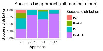
Attempts counted as Fail would not allow the completion of the task because of an impossible configuration. Partial overall quality meant that any part of the handling task had a flaw that would prevent the task from being completed, or had several minor flaws in each stage. The attempts marked as Fair had a minor flaw that did not affect the overall success of the task. Perfect attempts had no issues at all.
To run a Chi-Squared test with success frequencies, we considered Fair and Perfect attempts as successes, and failures otherwise. We found significant differences in the overall success for each approach (, ). Table 15 shows the result of applying the post-hoc pairwise Chi-squared tests with Bonferroni correction.
| PCP | PR2 | ||
| 3.005576e-01 | - | - | |
| PR2 | 1.277976e-09 | 1 | - |
| 2.198395e-02 | NaN | 1.000 |
As can be seen in Figure 46, in PCP, the number of successful completions was , a figure similar to the number of grasping attempts that involved no major collisions reported in the work by Leeper et al (Leeper et al., 2012). The large percentage of non-perfect executions in PCP is mostly due to the chosen method of value assignment, where we decided to evaluate two or more simple flaws in a manipulation as either Partial or Impossible. In summary, a third of users were able to indicate a flawless manipulation; had a single minor flaw; had an accumulation of minor flaws that we classified as failures; had outright impossible annotations like grasp misses or slips, or major collisions. In contrast, the PCP and PR2 experts had a success rate (albeit with some minor flaws), and novice PR2 users had a overall success rate, out of which had minor flaws.
In the work by Leeper et al (Leeper et al., 2012), large decreases in errors were obtained when introducing simple grasping hints. This may be accomplished by simply showing previous successful grasps, as annotations linked to the shape scaffold. We believe that most or all of the Partial, as well as some of the Fail marks due to grasping may be eradicated by using this approach. For Handling, one prevalent type of error involve grasping an object in a way that, when completing the handling would put the actual PR2’s wrist or forearm sections in contact with some obstacle or object in the work area. A simple modification to aide this would be to extend PCP with a slightly more complete gripper widget.
5. Discussion
5.1. Overview
There is a need for extracting accurate representations of a robot’s environment that contain noisy data or that have missing information. Given the rise in popularity of point cloud generating depth sensors, methods for extracting accurate object models from point clouds are needed. While automatic methods for recognizing or reconstructing objects have been developed, there is still a clear need for human input in the recovery of shapes and for assistance in specifying robotic actions.
Annotation of the segmented point cloud data has been shown to help refine object model reconstruction. Additionally, annotation can help guide robot actions or extend the information that an object model can provide. A compact structure that can hold a wide range of annotations is therefore, very useful for robotics.
The sweep-based scaffold structure is a simple and compact model that can represent a wide range of objects: from synthetic objects composed of primitive shapes, to organic ones with cavities and internal structures. The generalized-cylinder concept is an intuitively simple one to grasp and use as a proxy for more complicated shapes. PCP takes advantage of this fact and is able to provide an interface in which scaffolds can be quickly and accurately created to represent shapes.
Novice users showed that they could quickly learn to use an interface based on the scaffold representation, and that the resulting models had superior shape quality than that of the classic reconstruction method as implemented through KinFu. Additional training showed that an expert user is capable of obtaining shape accuracies that compete with CAD, but that require considerably less time to generate.
For the reconstruction phase, KinFu-generated point clouds were used, which required some time to create, and that encapsulated imprecisions in their generation that are propagated into the shape modeling with PCP (like the observed effect of point cloud objects looking smaller than their real counterparts). Object modeling does not require these fused point-clouds, but can be done from a single frame that contains enough information for a person to base its model on (which in some cases can be a small fragment of the complete shape). This is a particular benefit of methods that include humans.
While not currently optimized for that purpose, a further refinement of the modeling tools found in PCP could provide an interface that can be used to crowd-source complex or extensive digitalization efforts. Notably, the merging of user-generated shapes into prototypical ones showed a smaller average shape quality error than that of the average user. This indicated a potential for generating models that incorporate a sort of wisdom-of-the-crowds in the sense that there is a sort of voting scenario where agreement on shape features increase their reliability, and artifacts can be quickly eliminated. Further research is needed to investigate the potential of this approach.
In terms of grasping and simple manipulation of rigid objects, the object-relative annotations proved as precise and effective as that of live guided manipulation, and proved greatly superior to automatic grasping when the task context was considered. Even though the gripper used in the study (PR2 gripper) is rather simple, it was sufficient to compete a wide range of tasks. The representation used in the interface was only composed of the contact surfaces of the gripper, which shows how simple cues are sufficient for a human to achieve complex tasks. On the other hand, the minimalistic gripper representation did not provide the users an idea of collision areas, which resulted in some users inadvertently indicating actions that would cause the gripper to brush or even hit obstructions. A slightly less “minimalistic” gripper representation, with at least a simple graphical aspect to the occupancy of the part, could provide sufficient feedback to the user to increase the grasping and handling quality. While the only gripper used was for the PR2, extending PCL with additional grippers could be done modularly by providing a small file that contains the kinematic chain describing the gripper, and the visualization details for each one. In that sense, it could be a good idea to adopt a standard gripper description format, like the one used by GraspIt!. While the focus of this study is not fine-level grasping, the grasp annotation to the scaffold structure could be coupled with grasp-adjustment methods (Hsiao et al., 2010) to achieve even higher quality grasps. In addition, the grasping and handling annotations (represented by object-relative pose waypoints) could also be used to plan higher-level tasks. Even though this was not the focus of the thesis, the saved object models and their saved modes of use could be used as action primitives in the construction of more complex behaviors.
5.2. Limitations
Some shapes are still beyond the scope of this approach. This has to do with the time required to accurately represent complex topologies or high feature repetition. Some modeling languages compensate these problems by incorporating scripted part generation routines, that can be specified programmatically, or by using analytical expressions. Currently, no such features exist in PCP, but given the simplicity of the scaffold proxy, it would not take much to extend it with such capabilities.
Some grasping issues arose from the specific gripper we used for the experiments. Grasping the lid of the travel mug was difficult to indicate with no live-control. This is due to the relative size of the gripper to the lid. While grasps were successfully placed by the expert, this item was discarded from the user study because of this factor. As mentioned above, grasp-adjustment methods can be used to deal with this low-level problem.
5.3. Summary
The scaffold structure is a simple and expressive representation that was shown to help in the modeling of a wide range of shapes, as well as in the indication of three typical robotics tasks: grasping, pick-and-place, and articulated-object manipulation.
The DARPA Robotics Challenge emphasized the benefits of object models in indicating robotic models. It also showed the usefulness of having a way of quickly creating said models, and add them to the manipulation capabilities of the system. The teams that incorporated these models into their shared-control strategies were among the most successful ones.
On a high-level perspective, it is easy to see the benefits of the object-relative annotation approach to shared-control when considering that often the person that makes or knows the object (the object-maker) has a better idea of how it should be manipulated than the operator of the robot (the robot-mover). A simple tool, and a simple primitive should be available for object-makers to indicate these preferred modes of use.
6. Conclusions and Future Work
Shared control with Human-in-the-Loop is very useful, and in some cases, required, to get a robot to complete certain challenges. In a wide range of scenarios, continuous teleoperation has been superseded by a variety of shared-control mechanisms that explore different methods of splitting the workload that a human and a robot must complete.
While many strategies for autonomously planning parts of the interaction exist, object-relative annotations definitively have shown to provide excellent results. For maximum utility, these annotations should be saved in a simple, extensible and reusable container.
The shape-based annotation container that we present, called Point Cloud Scaffold was shown to provide enough expressive power to represent a wide variety of shapes that could be encountered by a service robot in an indoor environment. In addition, the annotations that can be attached to this structure benefit from the scaffold design itself: The hierarchical nature of the object (whole part scaffold slice handle), as well as the parameters that define the structures (slices have planes with normals, and scaffolds have sweep-axes).
The object modeling experiment shows that novice users can quickly learn to use these shape proxies to represent a wide range of objects with high accuracy, and that, given more experience, these objects can compete with CAD in terms of precision, while requiring a fraction of the time to generate.
The Pick-and-Place experiment showed that object-relative grasping and handling annotations can be very effective and easy to indicate, and that once created, their reuse is a simple matter of adjusting the waypoints. The grasp and pick-and-place annotations were tested on the PR2 and a high success rate was achieved, even for novice users.
6.1. Future Work
In the following sections, the possible next steps of this work are detailed.
6.1.1. Prototype Scaffolds and Mean Shapes
We would like to further investigate the potential of the mean shapes obtained from merging multiple individual user submissions. The steps would include the following:
-
(1)
Design a method for merging the PCSs themselves - using geometric properties - into a prototype scaffold. These annotation styles could be classified through the characteristics of the scaffolds themselves, like the number of parts or the sweep-axis direction. If more than one set of annotation styles is detected, obtain a prototype scaffold for each.
-
(2)
Evaluate the prototype scaffold in terms of shape reconstruction using the same metrics as in the user study presented in this thesis.
An advantage of obtaining a “running average” of user scaffolds (in the shape of the prototype scaffold) would be that an immediate shape hint would be available for novice users to base the shape on. If multiple styles exist, then multiple starting-points could be provided. This would have an immediate effect on reconstruction speed. A possible application could involve a continually refined system for crowdsourcing object reconstruction where modeling suggestions, as starting points, become available as more people participate.
6.1.2. Prototype Grasps
A consequence of merging scaffolds for reconstruction could be that the same might be done for grasping. A series of steps for doing so with the PCS structure would involve the following steps:
-
(1)
Design a method to transfer grasp annotations from an individual PCS to the prototype scaffold, while retaining or improving the grasp quality.
-
(2)
Design a method to cluster grasp annotations into different groups - using geometric and functional relationships - and merge each cluster into a prototype grasp.
-
(3)
Evaluate the prototype grasp in terms of object grasping using the same metrics as in the user study.
This would have an immediate impact on annotation speed as well. An added factor is the functional dimension. Prototype grasps could represent clusters that not only differentiate preference, but objective; e.g. choosing to grab a mug through the handle for pouring, or from the top, for stacking.
6.1.3. Scaffold Database and Annotation Transference
One benefit of the scaffold structures are that they can be easily classified through their structural properties into a database of object proxies that link to example underlying clouds and output meshes. In addition to the direct geometry, topological and functional properties can be used to further link the scaffolds within the database. Further annotation levels (like articulation or feature extraction) may generate additional parameters by which to link objects into classes and uses.
A related feature would be the transference of annotations between instances of the same class. An example would be to transfer the joint constraints to open a jar by turning the lid from one scaffold to another just by identifying that both fall under the same category: jars with screw lids, or in geometric/functional terms: ”containers with a screw joint to a link covering its concavity”.
A possible application of such a database may be the quick search and insertion of a scaffold into a scene point cloud. This feature, in conjunction to transference of annotations, could allow for a rapid geometric and functional annotation of multiple objects in an environment where a robot must operate. This could be done in a crowd-sourced manner for further speed gains.
6.1.4. Annotations For Articulated or Deformable Objects
An immediate extension of this work is to add articulation annotations that constrain the motion between the parts of a complex (multi-link) object. Any actuation by a robotic hand can be therefore constrained to the desired planes and exes of articulation. One possible level of annotations could relate to the reaction to force for each of the parts of the scaffold. The geometric properties of the scaffold re such that the occupied volume of the objects can be reshaped using a tetrahedral mesh and spring-based parametric annotations for the edges to denote resistance to force.
References
- (1)
- 3dW (2018) 2018. 3D Warehouse. (2018). https://3dwarehouse.sketchup.com/?hl=en.
-
clo (2018)
2018.
Cloud Composer app, PCL.
(2018).
https://github.com/PointCloudLibrary/pcl/tree/master/apps/cloud_composer. - sol (2018) 2018. Solidworks. (2018). http://www.solidworks.com/.
- Abdel-Malek et al. (2006) Karim Abdel-Malek, Jingzhou Yang, Denis Blackmore, and Ken Joy. 2006. Swept Volumes: Fundation, Perspectives, and Applications. International Journal of Shape Modeling 12, 01 (2006), 87–127. https://doi.org/10.1142/S0218654306000858
- Akal et al. (2004) T. Akal, R.D. Ballard, and G.F. Bass. 2004. The Application of Recent Advances in Underwater Detection and Survey Techniques to Underwater Archaeology. Uluburun Publishing. https://books.google.com/books?id=tiGrAAAACAAJ
- Akgun et al. (2012) Baris Akgun, Maya Cakmak, Jae Wook Yoo, and Andrea Lockerd Thomaz. 2012. Trajectories and keyframes for kinesthetic teaching: A human-robot interaction perspective. In Proceedings of the seventh annual ACM/IEEE international conference on Human-Robot Interaction. ACM, 391–398.
- Antonio Torralba (2018) Antonio Torralba. 2003(accessed March 3, 2018). The MIT-CSAIL Database of Objects and Scenes. (2003(accessed March 3, 2018)). http://web.mit.edu/torralba/www/database.html.
- Argall et al. (2009) Brenna D Argall, Sonia Chernova, Manuela Veloso, and Brett Browning. 2009. A survey of robot learning from demonstration. Robotics and autonomous systems 57, 5 (2009), 469–483.
- Arikan et al. (2013) Murat Arikan, Michael Schwarzler, Simon Flory, Michael Wimmer, and Stefan Maierhofer. 2013. O-Snap: Optimization-Based Snapping for Modeling Architecture. ACM Transactions on Graphics 32 (2013), 6:1—-6:15. https://doi.org/10.1145/XXXXXXX.YYYYYYY arXiv:1006.4903
- Autodesk (2018) Autodesk. 2018. 3Ds Max. (2018). https://www.autodesk.com/products/3ds-max/overview.
- Azad et al. (2007) Pedram Azad, Tamim Asfour, and Ruediger Dillmann. 2007. Stereo-based 6d object localization for grasping with humanoid robot systems. In Intelligent Robots and Systems, 2007. IROS 2007. IEEE/RSJ International Conference on. IEEE, 919–924.
- Balasubramanian et al. (2014) Ravi Balasubramanian, Ling Xu, Peter D Brook, Joshua R Smith, and Yoky Matsuoka. 2014. Physical human interactive guidance: Identifying grasping principles from human-planned grasps. Springer Tracts in Advanced Robotics 95, 4 (2014), 477–500. https://doi.org/10.1007/978-3-319-03017-3_22
- Ballard and Brown (1982) Dana H Ballard and Christopher M Brown. 1982. Computer Vision. NY: Prentice Hill (1982).
- Bauer (1972) David F Bauer. 1972. Constructing confidence sets using rank statistics. J. Amer. Statist. Assoc. 67, 339 (1972), 687–690.
- Berger et al. (2014) Matthew Berger, Pierre Alliez, Andrea Tagliasacchi, Lee M Seversky, Claudio T. Silva, Joshua a. Levine, and Andrei Sharf. 2014. State of the Art in Surface Reconstruction from Point Clouds. Proceedings of the Eurographics 2014, Eurographics STARs (2014), 161–185. https://doi.org/10.2312/egst.20141040
- Berger et al. (2017) Matthew Berger, Andrea Tagliasacchi, Lee M Seversky, Pierre Alliez, Gael Guennebaud, Joshua A Levine, Andrei Sharf, and Claudio T Silva. 2017. A survey of surface reconstruction from point clouds. In Computer Graphics Forum, Vol. 36. Wiley Online Library, 301–329.
- Binford (1975) Thomas Binford. 1975. Visual perception by computer. In Proc. IEEE Conf. on Systems and Control, 1975.
- Blazhenkova and Kozhevnikov (2010) Olesya Blazhenkova and Maria Kozhevnikov. 2010. Visual-object ability: A new dimension of non-verbal intelligence. Cognition 117, 3 (2010), 276–301. https://doi.org/10.1016/j.cognition.2010.08.021
- Boboc et al. (2012) RG Boboc, H Moga, and D Talaba. 2012. A review of current applications in teleoperation of mobile robots. Bulletin of the Transilvania University of Brasov Series I: Engineering Sciences 5, 54 (2012), 9–16.
- Bohg et al. (2013) Jeannette Bohg, Antonio Morales, Tamim Asfour, and Danica Kragic. 2013. Data-Driven Grasp Synthesis—A Survey. IEEE Transactions on Robotics 30, 2 (2013), 289–309. https://doi.org/10.1109/TRO.2013.2289018 arXiv:1309.2660
- Brook et al. (2011) Peter Brook, Matei Ciocarlie, and Kaijen Hsiao. 2011. Collaborative grasp planning with multiple object representations. In Robotics and Automation (ICRA …. 2851–2858. https://doi.org/10.1109/ICRA.2011.5980490
- Buehler (2015) Jennifer Elisabeth Buehler. 2015. Capabilities in Heterogeneous Multi Robot Systems. Ph.D. Dissertation. The University of New South Wales, Sydney, Sydney.
- Buhrmester et al. (2011) Michael Buhrmester, Tracy Kwang, and Samuel D Gosling. 2011. Amazon’s Mechanical Turk: A new source of inexpensive, yet high-quality, data? Perspectives on psychological science 6, 1 (2011), 3–5.
- Bülthoff et al. (1995) Heinrich H Bülthoff, Shimon Y Edelman, and Michael J Tarr. 1995. How are three-dimensional objects represented in the brain? Cerebral Cortex 5, 3 (1995), 247–260.
- Caissie et al. (2009) André F Caissie, François Vigneau, and Douglas A Bors. 2009. What does the Mental Rotation Test measure? An analysis of item difficulty and item characteristics. Open Psychology Journal 2, 1 (2009), 94–102.
- Caltech ([n. d.]) Caltech. [n. d.]. Computational Vision at Caltech. ([n. d.]). http://www.vision.caltech.edu/html-files/archive.html.
- Chang et al. (2015) Angel X Chang, Thomas Funkhouser, Leonidas Guibas, Pat Hanrahan, Qixing Huang, Zimo Li, Silvio Savarese, Manolis Savva, Shuran Song, Hao Su, et al. 2015. Shapenet: An information-rich 3d model repository. (2015).
- Chen et al. (2015) Si Chen, Muyuan Li, Kui Ren, and Chunming Qiao. 2015. Crowd Map: Accurate Reconstruction of Indoor Floor Plans from Crowdsourced Sensor-Rich Videos. In Proceedings - International Conference on Distributed Computing Systems, Vol. 2015-July. 1–10. https://doi.org/10.1109/ICDCS.2015.9
- Chen et al. (2013) Tao Chen, Zhe Zhu, Ariel Shamir, Shi-Min Hu, and Daniel Cohen-Or. 2013. 3-Sweep: Extracting Editable Objects from a Single Photo. ACM Transactions on Graphics (Proceedings of SIGGRAPH Asia 2013) 32, 6 (2013), Article 195.
- Ciocarlie et al. (2007) Matei Ciocarlie, Corey Goldfeder, and Peter Allen. 2007. Dexterous grasping via eigengrasps: A low-dimensional approach to a high-complexity problem. In Proceedings of the Robotics: Science & Systems 2007 Workshop-Sensing and Adapting to the Real World, Electronically published.
- Ciocarlie and Allen (2009) Matei T Ciocarlie and Peter K Allen. 2009. Hand posture subspaces for dexterous robotic grasping. The International Journal of Robotics Research 28, 7 (2009), 851–867.
- Ćurić et al. (2014) Vladimir Ćurić, Joakim Lindblad, Nataša Sladoje, Hamid Sarve, and Gunilla Borgefors. 2014. A new set distance and its application to shape registration. Pattern Analysis and Applications 17, 1 (2014), 141–152. https://doi.org/10.1007/s10044-012-0290-x
- Cutkosky (1989) Mark R Cutkosky. 1989. On Grasp Choice, Grasp Models, and the Design of Hands for Manufacturing Tasks. IEEE Transactions on Robotics and Automation 5, 3 (1989), 269–279. https://doi.org/10.1109/70.34763 arXiv:1106.3747
- Cyr and Kimia (2004) Christopher M Cyr and Benjamin B Kimia. 2004. A similarity-based aspect-graph approach to 3D object recognition. International Journal of Computer Vision 57, 1 (2004), 5–22.
- Dang and Allen (2012) Hao Dang and Peter K Allen. 2012. Semantic grasping: Planning robotic grasps functionally suitable for an object manipulation task. In Intelligent Robots and Systems (IROS), 2012 IEEE/RSJ International Conference on. IEEE, 1311–1317.
- De Croon et al. (2014) Guido De Croon, Paul K Gerke, and Ida Sprinkhuizen-Kuyper. 2014. Crowdsourcing as a methodology to obtain large and varied robotic data sets. In IEEE International Conference on Intelligent Robots and Systems. 1595–1600. https://doi.org/10.1109/IROS.2014.6942768
- Dou et al. (2015) Mingsong Dou, Jonathan Taylor, Henry Fuchs, Andrew Fitzgibbon, and Shahram Izadi. 2015. 3D scanning deformable objects with a single RGBD sensor. In IEEE Conference on Computer Vision and Pattern Recognition, CVPR 2015. IEEE Computer Society, 493–501.
- Dunn (1958) Olive Jean Dunn. 1958. Estimation of the means of dependent variables. The Annals of Mathematical Statistics (1958), 1095–1111.
- Dyer (2001) Charles R Dyer. 2001. Volumetric scene reconstruction from multiple views. In Foundations of image understanding. Springer, 469–489.
- Ekvall and Kragic (2007) Staffan Ekvall and Danica Kragic. 2007. Learning and evaluation of the approach vector for automatic grasp generation and planning. In Proceedings - IEEE International Conference on Robotics and Automation. 4715–4720. https://doi.org/10.1109/ROBOT.2007.364205
- Enes (2010) Aaron R Enes. 2010. Shared control of hydraulic manipulators to decrease cycle time. Ph.D. Dissertation. Georgia Institute of Technology.
- Farkhatdinov et al. (2010) Ildar Farkhatdinov, Jee-Hwan Ryu, and Jinung An. 2010. A preliminary experimental study on haptic teleoperation of mobile robot with variable force feedback gain. In Haptics Symposium, 2010 IEEE. IEEE, 251–256.
- Feix et al. (2016) Thomas Feix, Javier Romero, Heinz-Bodo Schmiedmayer, Aaron M Dollar, and Danica Kragic. 2016. The grasp taxonomy of human grasp types. IEEE Transactions on Human-Machine Systems 46, 1 (2016), 66–77.
- Ferland et al. (2009) François Ferland, François Pomerleau, Chon Tam Le Dinh, and François Michaud. 2009. Egocentric and exocentric teleoperation interface using real-time, 3D video projection. In Human-Robot Interaction (HRI), 2009 4th ACM/IEEE International Conference on. IEEE, 37–44.
- Ferrari and Canny (1992) Carlo Ferrari and John Canny. 1992. Planning optimal grasps. In Robotics and Automation, 1992. Proceedings., 1992 IEEE International Conference on. IEEE, 2290–2295.
- Fritsche et al. (2015) Lars Fritsche, Felix Unverzag, Jan Peters, and Roberto Calandra. 2015. First-person tele-operation of a humanoid robot. In Humanoid Robots (Humanoids), 2015 IEEE-RAS 15th International Conference on. IEEE, 997–1002.
- Fu et al. (2012) Yanwei Fu, Timothy M Hospedales, Tao Xiang, and Shaogang Gong. 2012. Attribute learning for understanding unstructured social activity. In European Conference on Computer Vision. Springer, 530–543.
- Gingold et al. (2012) Yotam Gingold, Ariel Shamir, and Daniel Cohen-Or. 2012. Micro perceptual human computation for visual tasks. ACM Transactions on Graphics (TOG) 31, 5 (2012), 119.
- Han et al. (2013) Jungong Han, Ling Shao, Dong Xu, and Jamie Shotton. 2013. Enhanced computer vision with Microsoft Kinect sensor: A review. IEEE Transactions on Cybernetics 43, 5 (2013), 1318–1334. https://doi.org/10.1109/TCYB.2013.2265378
- Hart and Staveland (1988) Sandra G Hart and Lowell E Staveland. 1988. Development of NASA-TLX (Task Load Index): Results of empirical and theoretical research. In Advances in psychology. Vol. 52. Elsevier, 139–183.
- Hertkorn (2016) Katharina Hertkorn. 2016. Shared Grasping: a Combination of Telepresence and Grasp Planning. KIT Scientific Publishing.
- Herzog et al. (2012) Alexander Herzog, Peter Pastor, Mrinal Kalakrishnan, Ludovic Righetti, Tamim Asfour, and Stefan Schaal. 2012. Template-based learning of grasp selection. In Robotics and Automation (ICRA), 2012 IEEE International Conference on. IEEE, 2379–2384.
- Hollander et al. (1973) Myles Hollander, Douglas A Wolfe, and Eric Chicken. 1973. Nonparametric statistical methods. John Wiley & Sons. 115–120. pages.
- Hsiao et al. (2010) Kaijen Hsiao, Sachin Chitta, Matei Ciocarlie, and E Gil Jones. 2010. Contact-reactive grasping of objects with partial shape information. In Intelligent Robots and Systems (IROS), 2010 IEEE/RSJ International Conference on. IEEE, 1228–1235.
- Hu et al. (2014) Ninghang Hu, Zhongyu Lou, Gwenn Englebienne, Ben JA Kröse, et al. 2014. Learning to Recognize Human Activities from Soft Labeled Data.. In Robotics: Science and Systems.
- Huang et al. (2013) Hui Huang, Shihao Wu, Daniel Cohen-Or, Minglun Gong, Hao Zhang, Guiqing Li, and Baoquan Chen. 2013. L1-medial skeleton of point cloud. ACM Trans. Graph. 32, 4 (2013), 65–1.
- Ishiguro et al. (2017) Yasuhiro Ishiguro, Kunio Kojima, Fumihito Sugai, Shunichi Nozawa, Yohei Kakiuchi, Kei Okada, and Masayuki Inaba. 2017. Bipedal oriented whole body master-slave system for dynamic secured locomotion with LIP safety constraints. In Intelligent Robots and Systems (IROS), 2017 IEEE/RSJ International Conference on. IEEE, 376–382.
- Johnson-Roberson et al. (2011) Matthew Johnson-Roberson, Jeannette Bohg, Gabriel Skantze, Joakim Gustafson, Rolf Carlson, Babak Rasolzadeh, and Danica Kragic. 2011. Enhanced visual scene understanding through human-robot dialog. In IEEE International Conference on Intelligent Robots and Systems. 3342–3348. https://doi.org/10.1109/IROS.2011.6048219
- Kehoe et al. (2015a) Ben Kehoe, Sachin Patil, Pieter Abbeel, and Ken Goldberg. 2015a. A Survey of Research on Cloud Robotics and Automation. IEEE Transactions on Automation Science and Engineering 12, 2 (2015), 398–409. https://doi.org/10.1109/TASE.2014.2376492
- Kehoe et al. (2015b) Ben Kehoe, Sachin Patil, Pieter Abbeel, and Ken Goldberg. 2015b. A Survey of Research on Cloud Robotics and Automation. IEEE Transactions on Automation Science and Engineering 12, 2 (2015), 398–409. https://doi.org/10.1109/TASE.2014.2376492
- Kent et al. (2014) David Kent, Morteza Behrooz, and Sonia Chernova. 2014. Crowdsourcing the construction of a 3D object recognition database for robotic grasping. In 2014 IEEE International Conference on Robotics and Automation (ICRA). 4526–4531. https://doi.org/10.1109/ICRA.2014.6907520
- Kent et al. (2017) David Kent, Carl Saldanha, and Sonia Chernova. 2017. A Comparison of Remote Robot Teleoperation Interfaces for General Object Manipulation. In Proceedings of the 2017 ACM/IEEE International Conference on Human-Robot Interaction. ACM, 371–379.
- Kholgade et al. (2014) Natasha Kholgade, Tomas Simon, Alexei Efros, and Yaser Sheikh. 2014. 3D object manipulation in a single photograph using stock 3D models. ACM Transactions on Graphics (TOG) 33, 4 (2014), 127.
- Khurshid et al. (2017) Rebecca P Khurshid, Naomi T Fitter, Elizabeth A Fedalei, and Katherine J Kuchenbecker. 2017. Effects of grip-force, contact, and acceleration feedback on a teleoperated pick-and-place task. IEEE transactions on haptics 10, 1 (2017), 40–53.
- Koenderink and van Doorn (1979) Jan J Koenderink and Andrea J van Doorn. 1979. The internal representation of solid shape with respect to vision. Biological cybernetics 32, 4 (1979), 211–216.
- Kostavelis and Gasteratos (2015) Ioannis Kostavelis and Antonios Gasteratos. 2015. Semantic mapping for mobile robotics tasks: A survey. Robotics and Autonomous Systems 66 (2015), 86–103.
- Lafarge and Alliez (2013) Florent Lafarge and Pierre Alliez. 2013. Surface reconstruction through point set structuring. In Computer Graphics Forum, Vol. 32. Wiley Online Library, 225–234.
- Leeper et al. (2012) Adam Eric Leeper, Kaijen Hsiao, Matei Ciocarlie, Leila Takayama, and David Gossow. 2012. Strategies for human-in-the-loop robotic grasping. In Proceedings of the seventh annual ACM/IEEE international conference on Human-Robot Interaction. ACM, 1–8.
- Li and Pollard (2005) Ying Li and Nancy S Pollard. 2005. A shape matching algorithm for synthesizing humanlike enveloping grasps. In Humanoid Robots, 2005 5th IEEE-RAS International Conference on. IEEE, 442–449.
- Li et al. (2011) Yangyan Li, Xiaokun Wu, Yiorgos Chrysathou, Andrei Sharf, Daniel Cohen-Or, and Niloy J Mitra. 2011. Globfit: Consistently fitting primitives by discovering global relations. In ACM Transactions on Graphics (TOG), Vol. 30. ACM, 52.
- Li et al. (1989) Zexiang Li, Ping Hsu, and Shankar Sastry. 1989. Grasping and coordinated manipulation by a multifingered robot hand. The International Journal of Robotics Research 8, 4 (1989), 33–50.
- Lipton et al. (2018) Jeffrey I Lipton, Aidan J Fay, and Daniela Rus. 2018. Baxter’s Homunculus: Virtual Reality Spaces for Teleoperation in Manufacturing. IEEE Robotics and Automation Letters 3, 1 (2018), 179–186.
- Liu et al. (2016) Jia Liu, Fangxiaoyu Feng, Yuzuko C Nakamura, and Nancy S Pollard. 2016. Annotating everyday grasps in action. In Dance notations and robot motion. Springer, 263–282.
- Martin et al. (2001) David Martin, Charless Fowlkes, Doron Tal, and Jitendra Malik. 2001. A database of human segmented natural images and its application to evaluating segmentation algorithms and measuring ecological statistics. In Computer Vision, 2001. ICCV 2001. Proceedings. Eighth IEEE International Conference on, Vol. 2. IEEE, 416–423.
- Martins et al. (2015) Henrique Martins, Ian Oakley, and Rodrigo Ventura. 2015. Design and evaluation of a head-mounted display for immersive 3D teleoperation of field robots. Robotica 33, 10 (2015), 2166–2185.
- Mccrae et al. (2013) James Mccrae, Niloy J Mitra, and Karan Singh. 2013. Surface perception of planar abstractions. ACM Transactions on Applied Perception (TAP) 10, 3 (2013), 14.
- McCrae et al. (2011) James McCrae, Karan Singh, and Niloy J. Mitra. 2011. Slices: A Shape-proxy Based on Planar Sections. ACM Transactions on Graphics 30, 6, Article 168 (2011), 12 pages.
- Miller and Allen (2004) Andrew T Miller and Peter K Allen. 2004. Graspit! a versatile simulator for robotic grasping. IEEE Robotics & Automation Magazine 11, 4 (2004), 110–122.
- Miller et al. (2003) Andrew T Miller, Steffen Knoop, Henrik I Christensen, and Peter K Allen. 2003. Automatic grasp planning using shape primitives. In IEEE International Conference on Robotics and Automation, Vol. 2. 1824–1829 vol.2. https://doi.org/10.1109/ROBOT.2003.1241860
- Mirtich (1996) Brian Mirtich. 1996. Fast and accurate computation of polyhedral mass properties. Journal of graphics tools 1, 2 (1996), 31–50.
- Moons et al. (2009) Theo Moons, Luc Van Gool, and Maarten Vergauwen. 2009. 3D Reconstruction from multiple images. Foundations and Trends in Computer Graphics and Vision. 4, 4 (2009), 287–404.
- Naeve and Eklundh (1995) Ambjörn Naeve and Jan-olof Eklundh. 1995. Representing Generalized Cylinders. In Proceedings of the Europe-China Workshop on Geometrical Modeling and Invariants for Computer Vision. 63–70.
- Nan et al. (2010) Liangliang Nan, Andrei Sharf, Hao Zhang, Daniel Cohen-Or, and Baoquan Chen. 2010. SmartBoxes for interactive urban reconstruction. ACM Transactions on Graphics 29, 4 (2010), 1. https://doi.org/10.1145/1833351.1778830
- Napier (1956) John R Napier. 1956. The prehensile movements of the human hand. Bone & Joint Journal 38, 4 (1956), 902–913.
- Newcombe et al. (2011) Richard A Newcombe, Shahram Izadi, Otmar Hilliges, David Molyneaux, David Kim, Andrew J Davison, Pushmeet Kohi, Jamie Shotton, Steve Hodges, and Andrew Fitzgibbon. 2011. KinectFusion: Real-time dense surface mapping and tracking. In Mixed and augmented reality (ISMAR), 2011 10th IEEE international symposium on. IEEE, 127–136.
- Nguyen et al. (2017) Thanh Duc Nguyen, Binh-Son Hua, Lap-Fai Yu, and Sai Kit Yeung. 2017. A Robust 3D-2D Interactive Tool for Scene Segmentation and Annotation. IEEE Transactions on Visualization and Computer Graphics (2017).
- Nikandrova and Kyrki (2015) Ekaterina Nikandrova and Ville Kyrki. 2015. Category-based task specific grasping. Robotics and Autonomous Systems 70 (2015), 25–35.
- Osentoski et al. (2010) Sarah Osentoski, Christopher Crick, Grayin Jay, and Odest Chadwicke OC Jenkins. 2010. Crowdsourcing for closed loop control. Proc. of the NIPS Workshop on Computational Social Science and the Wisdom of Crowds, NIPS (2010), 4–7.
- Osher and Fedkiw (2001) Stanley Osher and Ronald P Fedkiw. 2001. Level set methods: an overview and some recent results. Journal of Computational physics 169, 2 (2001), 463–502.
- Oviatt (2006) Sharon Oviatt. 2006. Human-Centered Design Meets Cognitive Load Theory : Designing Interfaces that Help People Think. ACM international Conference on Multimedia (2006), 871–880. https://doi.org/10.1145/1180639.1180831
- Papon (2012) Jeremie Papon. 2012. PCL Developers blog: Jeremie Papon. (2012). http://www.pointclouds.org/blog/gsoc12/jpapon/index.php.
- Patron-Perez et al. (2012) Alonso Patron-Perez, Marcin Marszalek, Ian Reid, and Andrew Zisserman. 2012. Structured learning of human interactions in TV shows. IEEE Transactions on Pattern Analysis and Machine Intelligence 34, 12 (2012), 2441–2453.
- Piater et al. (2011) Justus Piater, Sébastien Jodogne, Renaud Detry, Dirk Kraft, Norbert Krüger, Oliver Kroemer, and Jan Peters. 2011. Learning visual representations for perception-action systems. The International Journal of Robotics Research 30, 3 (2011), 294–307.
- Pollard et al. (2002) Nancy S Pollard, Jessica K Hodgins, Marcia J Riley, and Christopher G Atkeson. 2002. Adapting human motion for the control of a humanoid robot. In Robotics and Automation, 2002. Proceedings. ICRA’02. IEEE International Conference on, Vol. 2. IEEE, 1390–1397.
- Popović et al. (2011) Mila Popović, Gert Kootstra, Jimmy Alison Jørgensen, Danica Kragic, and Norbert Krüger. 2011. Grasping unknown objects using an early cognitive vision system for general scene understanding. In Intelligent Robots and Systems (IROS), 2011 IEEE/RSJ International Conference on. IEEE, 987–994.
- Prelec et al. (2017) Dražen Prelec, H Sebastian Seung, and John McCoy. 2017. A solution to the single-question crowd wisdom problem. Nature 541, 7638 (2017), 532.
- Ramos et al. (2015) Joao Ramos, Albert Wang, and Sangbae Kim. 2015. A Balance Feedback Human Machine Interface for humanoid teleoperation in dynamic tasks. In IEEE International Conference on Intelligent Robots and Systems, Vol. 2015-Decem. 4229–4235. https://doi.org/10.1109/IROS.2015.7353976
- Reis et al. (2012) Helena M Reis, Simone S Borges, Vinicius H S Durelli, Luis Fernando De S. Moro, Anarosa A F Brandão, Ellen F Barbosa, Le??nidas O. Brandão, Seiji Isotani, Patricia A Jaques, and Ig I. Bittencourt. 2012. Towards reducing cognitive load and enhancing usability through a reduced graphical user interface for a dynamic geometry system: An experimental study. In Proceedings - 2012 IEEE International Symposium on Multimedia, ISM 2012. 445–450. https://doi.org/10.1109/ISM.2012.91
- Restrepo et al. (2017) Susana Sánchez Restrepo, Gennaro Raiola, Pauline Chevalier, Xavier Lamy, and Daniel Sidobre. 2017. Iterative virtual guides programming for human-robot comanipulation. In Advanced Intelligent Mechatronics (AIM), 2017 IEEE International Conference on. IEEE, 219–226.
- Rodolà et al. (2013) Emanuele Rodolà, Andrea Albarelli, Filippo Bergamasco, and Andrea Torsello. 2013. A Scale Independent Selection Process for 3D Object Recognition in Cluttered Scenes. International Journal of Computer Vision 1, 102 (2013), 129–145.
- Romero et al. (2009) Javier Romero, Hedvig Kjellstrom, and Danica Kragic. 2009. Modeling and evaluation of human-to-robot mapping of grasps. In Advanced Robotics, 2009. ICAR 2009. International Conference on. IEEE, 1–6.
- Rouanet et al. (2013) Pierre Rouanet, Pierre Yves Oudeyer, Fabien Danieau, and David Filliat. 2013. The impact of human-robot interfaces on the learning of visual objects. IEEE Transactions on Robotics 29, 2 (2013), 525–541. https://doi.org/10.1109/TRO.2012.2228134
- Ruffaldi et al. (2017) Emanuele Ruffaldi, Alessandro Di Fava, Claudio Loconsole, Antonio Frisoli, and Carlo A Avizzano. 2017. Vibrotactile feedback for aiding robot kinesthetic teaching of manipulation tasks. In Robot and Human Interactive Communication (RO-MAN), 2017 26th IEEE International Symposium on. IEEE, 818–823.
- Russakovsky et al. (2015) Olga Russakovsky, Li-Jia Li, and Li Fei-Fei. 2015. Best of both worlds: human-machine collaboration for object annotation. In Proceedings of the IEEE Conference on Computer Vision and Pattern Recognition. 2121–2131.
- Rusu and Cousins (2011) Radu Bogdan Rusu and Steve Cousins. 2011. 3D is here: Point Cloud Library (PCL). In IEEE International Conference on Robotics and Automation (ICRA). Shanghai, China.
- Schoenberg and Sharma (1973) IJ Schoenberg and Ambikeshwar Sharma. 1973. Cardinal interpolation and spline fucntions V. The B-splines for cardinal Hermite interpolation. Linear Algebra Appl. 7, 1 (1973), 1–42.
- Schroeder et al. (1994) William J Schroeder, William E Lorensen, and Steve Linthicum. 1994. Implicit modeling of swept surfaces and volumes. In Proceedings of the conference on Visualization’94. IEEE Computer Society Press, 40–45.
- Sengupta et al. (2013) Sunando Sengupta, Eric Greveson, Ali Shahrokni, and Philip H.S. Torr. 2013. Urban 3D semantic modelling using stereo vision. In Proceedings - IEEE International Conference on Robotics and Automation. 580–585. https://doi.org/10.1109/ICRA.2013.6630632
- Sharf et al. (2007) Andrei Sharf, Thomas Lewiner, Gil Shklarski, Sivan Toledo, and Daniel Cohen-Or. 2007. Interactive topology-aware surface reconstruction. ACM Transactions on Graphics 26, 3 (2007), 43. https://doi.org/10.1145/1276377.1276431
- Shtof et al. (2013) A. Shtof, A. Agathos, Y. Gingold, A. Shamir, and D. Cohen-Or. 2013. Geosemantic snapping for sketch-based modeling. Computer Graphics Forum 32, 2 PART2 (2013), 245–253. https://doi.org/10.1111/cgf.12044
- Singh et al. (2013) Ashish Singh, Stela H Seo, Yasmeen Hashish, Masayuki Nakane, James E Young, and Andrea Bunt. 2013. An interface for remote robotic manipulator control that reduces task load and fatigue. In RO-MAN, 2013 IEEE. IEEE, 738–743.
- Sorokin et al. (2010) Alexander Sorokin, Dmitry Berenson, Siddhartha S. Srinivasa, and Martial Hebert. 2010. People helping robots helping people: Crowdsourcing for grasping novel objects. In IEEE/RSJ 2010 International Conference on Intelligent Robots and Systems, IROS 2010 - Conference Proceedings. 2117–2122. https://doi.org/10.1109/IROS.2010.5650464
- St. John et al. (2001) Mark St. John, Michael B Cowen, Harvey S Smallman, and Heather M Oonk. 2001. The use of 2D and 3D displays for shape-understanding versus relative-position tasks. Human Factors 43, 1 (2001), 79–98.
- Sucan and Chitta (2013) Ioan A Sucan and Sachin Chitta. 2013. Moveit! Online at http://moveit. ros. org (2013).
- Sun et al. (2013) Min Sun, Shyam Sunder Kumar, Gary Bradski, and Silvio Savarese. 2013. Object detection, shape recovery, and 3D modelling by depth-encoded hough voting. Computer Vision and Image Understanding 117, 9 (2013), 1190–1202. https://doi.org/10.1016/j.cviu.2013.05.002
- Sung et al. (2015) Jaeyong Sung, Seok Hyun Jin, and Ashutosh Saxena. 2015. Robobarista: Object Part based Transfer of Manipulation Trajectories from Crowd-sourcing in 3D Pointclouds. (2015). https://doi.org/10.1007/978-3-319-60916-4_40 arXiv:1504.03071
- Teichman et al. (2013) Alex Teichman, Jake T. Lussier, and Sebastian Thrun. 2013. Learning to segment and track in RGBD. IEEE Transactions on Automation Science and Engineering 10, 4 (2013), 841–852. https://doi.org/10.1109/TASE.2013.2264286
- Tory et al. (2006) Melanie Tory, Arthur E Kirkpatrick, M Stella Atkins, and Torsten Moller. 2006. Visualization task performance with 2D, 3D, and combination displays. IEEE transactions on visualization and computer graphics 12, 1 (2006), 2–13.
- Ummenhofer and Brox (2013) Benjamin Ummenhofer and Thomas Brox. 2013. Point-based 3d reconstruction of thin objects. In Computer Vision (ICCV), 2013 IEEE International Conference on. IEEE, 969–976.
- Vandenberg and Kuse (1978) Steven G Vandenberg and Allan R Kuse. 1978. Mental rotations, a group test of three-dimensional spatial visualization. Perceptual and motor skills 47, 2 (1978), 599–604.
- Wang and Hua (2011) Meng Wang and Xian-Sheng Hua. 2011. Active learning in multimedia annotation and retrieval. ACM Transactions on Intelligent Systems and Technology 2, 2 (2011), 1–21. https://doi.org/10.1145/1899412.1899414
- Wang et al. (2012) Tinghuai Wang, Bo Han, and John Collomosse. 2012. Touchcut: Single-touch object segmentation driven by level set methods. In Acoustics, Speech and Signal Processing (ICASSP), 2012 IEEE International Conference on. IEEE, 881–884.
- Weisz et al. (2013) Jonathan Weisz, Carmine Elvezio, and Peter K Allen. 2013. A user interface for assistive grasping. In Intelligent Robots and Systems (IROS), 2013 IEEE/RSJ International Conference on. IEEE, 3216–3221.
- Whelan et al. (2012) Thomas Whelan, Michael Kaess, Maurice Fallon, Hordur Johannsson, John Leonard, and John McDonald. 2012. Kintinuous: Spatially extended kinectfusion. (2012).
- Wurm et al. (2010) K M Wurm, a Hornung, M Bennewitz, C Stachniss, and W Burgard. 2010. OctoMap: A probabilistic, flexible, and compact 3D map representation for robotic systems. Proc of the ICRA 2010 workshop on best practice in 3D perception and modeling for mobile manipulation 16, 3 (2010), 403–412. https://doi.org/10.1.1.176.7242
- Xiang et al. (2016) Yu Xiang, Wonhui Kim, Wei Chen, Jingwei Ji, Christopher Choy, Hao Su, Roozbeh Mottaghi, Leonidas Guibas, and Silvio Savarese. 2016. Objectnet3D: A large scale database for 3D object recognition. In Lecture Notes in Computer Science (including subseries Lecture Notes in Artificial Intelligence and Lecture Notes in Bioinformatics), Vol. 9912 LNCS. 160–176. https://doi.org/10.1007/978-3-319-46484-8_10 arXiv:1311.2901
- Yamauchi (2004) Brian M Yamauchi. 2004. PackBot: A versatile platform for military robotics. In Unmanned Ground Vehicle Technology VI, Vol. 5422. International Society for Optics and Photonics, 228–238.
- Yin et al. (2014) Kangxue Yin, Hui Huang, Hao Zhang, Minglun Gong, Daniel Cohen-or, and Baoquan Chen. 2014. Morfit : Interactive Surface Reconstruction from Incomplete Point Clouds with Curve-Driven Topology and Geometry Control. ACM Transactions on Graphics (TOG) 33, 6 (2014), 202:1—-202:12. https://doi.org/10.1145/2661229.2661241
- Yoon and Kim (2006) Seung-Hyun Yoon and Myung-Soo Kim. 2006. Sweep-based Freeform Deformations. In Computer Graphics Forum, Vol. 25. Wiley Online Library, 487–496.
- Zhang et al. (2014) Qing Zhang, Bo Fu, Mao Ye, and Ruigang Yang. 2014. Quality dynamic human body modeling using a single low-cost depth camera. In Proceedings of the IEEE Computer Society Conference on Computer Vision and Pattern Recognition. 676–683. https://doi.org/10.1109/CVPR.2014.92
- Zheng et al. (2012) Youyi Zheng, Xiang Chen, Ming-Ming Cheng, Kun Zhou, Shi-Min Hu, and Niloy J Mitra. 2012. Interactive images: cuboid proxies for smart image manipulation. ACM Trans. Graph. 31, 4 (2012), 99–1.
- Zhou et al. (2015) Yang Zhou, Kangxue Yin, Hui Huang, Hao Zhang, Minglun Gong, and Daniel Cohen-Or. 2015. Generalized cylinder decomposition. ACM Transactions on Graphics (TOG) 34, 6 (2015), 1–14. https://doi.org/10.1145/2816795.2818074
- Zivkovic et al. (2008) Zoran Zivkovic, Olaf Booij, Ben Kröse, Elin A Topp, and Henrik I Christensen. 2008. From sensors to human spatial concepts: An annotated data set. IEEE Transactions on Robotics 24, 2 (2008), 501–505.