Optimized Path Planning for Inspection by Unmanned Aerial Vehicles Swarm with Energy Constraints
Abstract
Autonomous inspection of large geographical areas is a central requirement for efficient hazard detection and disaster management in future cyber-physical systems such as smart cities. In this regard, exploiting unmanned aerial vehicle (UAV) swarms is a promising solution to inspect vast areas efficiently and with low cost. In fact, UAVs can easily fly and reach inspection points, record surveillance data, and send this information to a wireless base station (BS). Nonetheless, in many cases, such as operations at remote areas, the UAVs cannot be guided directly by the BS in real-time to find their path. Moreover, another key challenge of inspection by UAVs is the limited battery capacity. Thus, realizing the vision of autonomous inspection via UAVs requires energy-efficient path planning that takes into account the energy constraint of each individual UAV. In this paper, a novel path planning algorithm is proposed for performing energy-efficient inspection, under stringent energy availability constraints for each UAV. The developed framework takes into account all aspects of energy consumption for a UAV swarm during the inspection operations, including energy required for flying, hovering, and data transmission. It is shown that the proposed algorithm can address the path planning problem efficiently in polynomial time. Simulation results show that the proposed algorithm can yield substantial performance gains in terms of minimizing the overall inspection time and energy. Moreover, the results provide guidelines to determine parameters such as the number of required UAVs and amount of energy, while designing an autonomous inspection system.
I Introduction
Autonomous inspection of large geographical areas is a key requirement to increase safety and optimize the operation of future cyber-physical systems, such as smart cities, smart farms [WOLFERT201769], and smart oil fields [sof2]. In smart farms, for example, there is a need to inspect large farm lands for signs of pest attacks and to spray pesticide locally over vulnerable regions. Meanwhile, smart oil fields require constant monitoring of the fields for detecting signs of oil spills. Another prominent application of autonomous inspection is in post-disaster management, after natural calamities like hurricanes or floods, to perform search-and-rescue operations.
In this regard, inspection by unmanned aerial vehicles (UAVs) [7412759] is seen as an attractive solution due to the following reasons: 1) UAVs can fly and bypass obstacles which can result in reducing the inspection time; 2) UAVs are relatively cheaper than dispatching human personnel; and 3) UAVs can easily operate in adverse location that can be dangerous to human workers. For instance, a byproduct of oil extraction is Hydrogen Sulphide (H2S), a colorless and odorless toxic gas that makes oil spill inspection challenging. In such scenarios, a group of UAVs, also known as a UAV swarm, can perform coordinated inspection and manage the inspection tasks more efficiently with a low cost and within a limited time.
Nonetheless, several challenges must be addressed to realize practical autonomous inspection by a UAV swarm. First, each UAV has a limited battery capacity that can support a limited flight time. Thus, UAVs must work collaboratively to inspect a large geographical area. Second, a UAV swarm may include heterogeneous types of UAVs with different flying capabilities and energy efficiency. Third, in many scenarios, UAVs cannot be fully controlled by a wireless base station (BS) to find their path, e.g., in post-disaster situations where the communication infrastructure is damaged. Fourth, as the UAV’s distance from the BS increases, more transmission power is required by the UAV to maintain a minimum data transmission rate. Finally, in most applications, the inspection must be performed in a limited time. For example, in oil spill detection, a few minutes saving in the inspection time can prevent drastic oil spill incidents. Therefore, reaping the full benefits of UAV swarms for autonomous inspection mandates efficient path planning for each UAV to minimize the overall energy consumption, while accounting for the limited energy of each UAV.
Recently, several works have been proposed in the literature to address path planning for autonomous inspection by a UAV swarm [PP1, PP2, 7888557, 7192644, 8255824, PP4, 8243572]. The authors in [PP1] propose an age-optimal trajectory planning for UAVs to collect data from ground sensor nodes. In [PP2], a framework is developed to exploit UAVs, serving as relay nodes, to minimize the peak age-of-information for a pair of nodes in an Internet-of-Things (IoT) network. The authors in [7888557] find an energy-efficient path planning scheme for a fixed-wing UAV that communicates with a ground user. Moreover, the work in [7192644] studies an energy-efficient cooperative relaying by a set of UAVs, while considering circular flight trajectories. Meanwhile, [8255824] proposes a scheme to jointly optimizing the UAV’s trajectory and transmit power allocation. The work in [PP4] presents a tutorial on the applications of UAVs in wireless communications and studies fundamental tradeoffs in UAV-enabled wireless networks. With regard to optimizing UAV deployments for inspection applications, [8243572] presents a path planning scheme for the inspection of photovoltaic farms by a UAV swarm.
Although interesting, the body of work in [PP1, PP2, 7192644, 8255824, PP4] mainly focuses on communications aspects of UAVs, without considering specific constraints that affect inspection operations, such as the impact of UAV’s weight, energy requirements for hovering, and flight conditions. Moreover, some of the existing works consider path planning for specific scenarios, such as the works in [7888557] and [7192644], that solely focus on circular trajectory for the UAVs. In addition, [8243572] does not consider communications constraints such as minimum required data rate. Meanwhile, several works in the literature, such as [PP1, PP2, 7192644] and [8255824], primarily focus on minimizing the time that a wireless user is visited by the UAV swarm. While this metric is important in sensor networks and IoT, for inspection operations, energy-efficient path planning is more critical. Additionally, missing from the prior art, there is a need for performance analysis to determine parameters such as the number of required UAVs and energy requirements for inspection operations by a UAV swarm.
The main contribution of this work is a novel path planning algorithm to minimize the overall energy consumption for inspection by a UAV swarm, while accounting for the heterogeneous features of UAVs and their unique energy constraints. In particular, we first propose an energy consumption model that jointly captures the required energy for flying, hovering, and transmission of recorded inspection data by a UAV to the wireless BS. To solve the autonomous inspection problem, we model the area as an undirected, weighted graph with critical inspection points as the vertices of the graph and the required energy for monitoring an inspection point as the weight of the edge. Using the graph-based model, we develop a novel path planning algorithm that exploits the analogies between autonomous inspection and the -traveling repairmen problem [PP6], while considering the limited energy budget of each UAV. In particular, the proposed algorithm jointly optimizes the trajectory of all energy-constrained UAVs in a swarm, in order to minimize the overall average inspection energy. Simulation results show that the proposed algorithm outperforms the distance-based path planning, both in terms of required time and energy for inspection of an area. The results also shed light on design and performance analysis of the autonomous inspection by a UAV swarm, in terms of the number of required UAVs, average inspection time, and energy consumption.
The rest of paper is organized as follows. Section II presents the system model and problem formulation. Section III presents the proposed solution. Simulation results are provided in Section IV. Section V concludes the paper.
II System Model
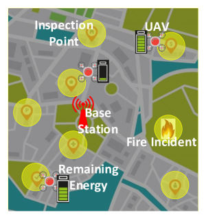
Consider a swarm of heterogeneous UAVs – with different energy efficiency and battery size – in a set that are used to perform autonomous inspection of a square area. Fig. 1 shows an example scenario of autonomous inspection by a UAV swarm. A wireless BS, located at the origin , also serves as the UAVs’ base where the UAVs start their travel. Each UAV is constrained with an energy budget . In addition, let be the set of inspection points that must be visited by at least one UAV during a time window, determined by the actual inspection application. For example, for post-disaster rescue operations, the inspection time may not exceed few minutes. Next, we find the energy consumption of each UAV as a function of different parameters, such as the location, energy efficiency, and traversed distance. Without loss of generality, we focus on quadrotor UAVs, while other types of UAVs can also be taken into account.
Energy consumption for monitoring of an inspection point by a UAV includes three components: 1) Flight energy: the required energy to fly to the point of interest from another location; 2) Transmission energy: the required energy to transmit the recorded data (photo or video) from the inspection point to the BS; and 3) Hovering energy: the energy consumption for remaining still on the air during the time that takes for a UAV to record and transmit a data. Next, we characterize each energy consumption component.
II-A Flying and Hovering Energy Consumption
The energy consumption by a flying UAV is mainly spent to overcome the gravity for staying in the air, as well as drag forces due to wind and forward motions. Building on the model in [PP5], the minimum power with forward motion for a UAV is given by
| (1) |
where is the induced velocity required for a given thrust , is the average ground speed of the UAV, and denotes the pitch angle. For a UAV with mass , including the mass of the UAV body and battery, the required thrust is:
| (2) |
where is the gravitational constant and is the drag force that depends on the air speed, density of air , and the drag coefficient. Given a thrust , the induced velocity can be calculated by solving the following nonlinear equation [PP5]:
| (3) |
where and represent, respectively, the diameter and number of UAV rotors. The theoretical power consumption in (1) can be used to find the actual power consumption by a UAV as:
| (4) |
where is the power efficiency of the UAV , known empirically. With that in mind, the total flying energy that an arbitrary UAV consumes to traverse distance is:
| (5) |
Furthermore, the actual power consumption for hovering of UAV is [PP5]:
| (6) |
where is the theoretical minimum power for hovering.
II-B Transmission Energy Consumption
The energy consumption for transmission of recorded data from the inspection point cannot be ignored in many cases where: 1) The distance between the UAV and the BS is large; and 2) The size of the recorded content is large (such as high-definition videos). Considering the inspection of a point at , the path loss of the wireless link in dB is given by:
| (7) |
where is the path loss at a reference distance, is the path loss exponent, and represents the shadowing effect in dB scale. Using (7), we can find the achievable data rate of the uplink between a UAV and the BS as follows111Although we consider log-distance path loss channel model, small-scale fading can also be easily accommodated in (8).:
| (8) |
where , , and denote, respectively, the bandwidth, the transmit power of UAV, and the noise power spectral density. In (8), orthogonal bandwidth allocation is considered across UAVs, thus, there is no interference between simultaneous UAV transmissions. To find the transmission energy consumption, let be the minimum required uplink data rate for successful transmission of the recorded content. From (8) and subject to the data rate requirement , one can easily find the minimum required transmit power for a UAV . Meanwhile, the energy consumption for transmission of a data packet with size bits will be:
| (9) |
where is the over-the-air transmission latency. From (5)-(9), we can conclude that the overall energy consumption by a UAV to fly from the base, located at , to inspect a destination point is:
| (10) |
where shows the inspection point visited immediately before . In (II-B), is the distance between points and and depends on the location of inspection point . In fact, given that , (II-B) allows to recursively find the overall inspection energy consumption for any arbitrary point.
II-C Problem Formulation
To study the path planning problem, we model the inspection area as an undirected, weighted graph , corresponding to the UAV , where the vertices are inspection points and the weight of each edge between points is and can be found from (II-B). The goal here is to find the best trajectory for each UAV across the inspection points (i.e., path planning) in order to minimize the overall inspection time. The union of these trajectories must cover all the inspection points in the set . Prior to formulating the problem, we use the following definitions:
Definition 1.
The trajectory of a UAV is defined as a tree , inside the graph , with the root starting at the location of the BS, .
The main reason to define each UAV’s trajectory as a tree is to avoid cycles within the inspection path. Associated with each trajectory, we can define a cost in terms of energy consumption as follows: