Counter-propagating charge transport in the quantum Hall effect regime
††preprint: APS/123-QEDThe quantum Hall effect, observed in a two-dimensional electron gas subjected to a perpendicular magnetic field, imposes a 1D-like chiral, downstream, transport of charge carriers along the sample edges. Although this picture remains valid for electrons and Laughlin’ s fractional quasiparticles, it no longer holds for quasiparticles in the so-called hole-conjugate states. These states are expected, when disorder and interactions are weak, to harbor upstream charge modes. However, so far, charge currents were observed to flow exclusively downstream in the quantum Hall regime. Studying the canonical spin-polarized and spin-unpolarized hole-like states in GaAs-AlGaAs heterostructures, we observed a significant upstream charge current at short propagation distances in the spin unpolarized state.
Elementary charge excitations in the quantum Hall effect (QHE) flow downstream along the edge of a two-dimensional electron gas (2DEG), with the downstream chirality imposed by the magnetic field (Klitzing et al., 1980). In the fractional regime (Tsui et al., 1982) this statement remains valid only for particle-like (Laughlin’s) states (Laughlin, 1983; Beenakker, 1990; Wen, 1991); in contrast, hole-like states (filling factors such that with ), are expected to harbor counter-propagating (downstream and upstream) charge excitations (MacDonald, 1990). In a non-interacting and scattering-free model, a downstream charge mode was predicted to be accompanied by an upstream mode, leading to a two-terminal conductance of where and are respectively the electron charge and the Planck constant. However, experimentally, only downstream charge modes (Ashoori et al., 1992; Sabo et al., 2017) with a two-terminal conductance of accompanied by upstream neutral modes(Kane et al., 1994; Meir, 1994; Wang et al., ; Bid et al., 2010; Gurman et al., 2012; Inoue et al., 2014; Rosenblatt et al., 2017) have been found. A recent experiment (Grivnin et al., 2014) measured conductance of an unequilibrated downstream channels at narrow regions (4 wide) of the polarized state; the results were consistent with the model from (MacDonald, 1990) but no direct measurement of the upstream current was made. Although the majority of the studies were concentrated on the spin-polarized state, there has been recent interest in its spin-unpolarized counterpart (Eisenstein et al., 1990; Kronmüller et al., 1998, 1999; Chakraborty, 2000; Smet et al., 2001a; Kraus et al., ; Hayakawa et al., 2012; Moore et al., 2017) - as a potential host for para-fermions when coupled to superconducting contacts (Mong et al., 2014; Clarke et al., 2014; Wu et al., 2018). In the Composite Fermion (CF) picture, one can construct two kinds of states in the : An unpolarized state, emerging at lower magnetic fields, with two quantum levels that have the same orbital quantum number
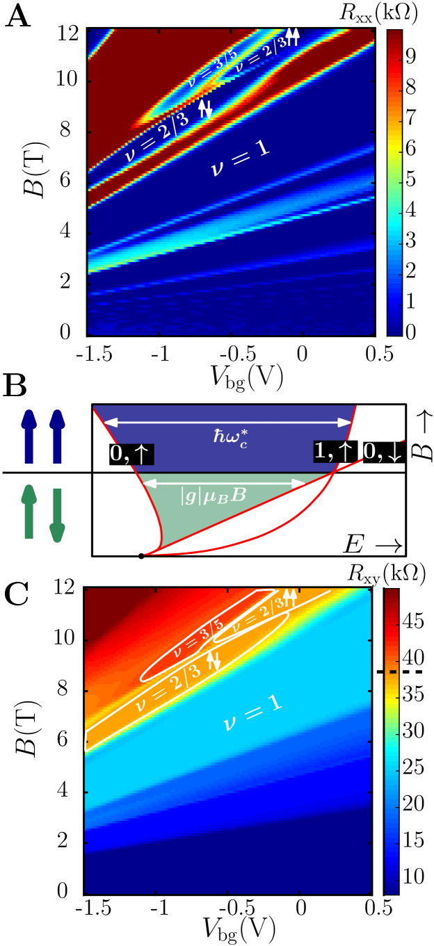
but opposite spin configurations: (0,) and (0,) (Fig. 1B) (Jain, 1989), and a polarized state, emerging at high magnetic fields, with two quantum levels having the same spin but different orbitals (0,) and (1,) (Kukushkin et al., 1999). The majority of previous experiments in the unpolarized state focused on characterizing the spin domains structure in the bulk (Verdene et al., 2007; Hayakawa et al., 2012; Moore et al., 2017) or the nuclear spin polarization occurring at high currents (Smet et al., 2001b; Kraus et al., ; Huels et al., 2004; Verdene et al., 2007; Hennel et al., 2016; Cho et al., 1998; Kronmüller et al., 1998, 1999; Li et al., 2012; Smet et al., 2002). Still, the configuration of edge channels for this state remains elusive: on the one hand, no upstream channel is expected in the CF picture, on the other, because the effective K-Matrix in the CF basis is the same for both states, an upstream mode should occur also in the unpolarized case (Wu et al., 2012). Here, we studied the two flavors of the state along short distance (a few m) and found a substantial upstream charge current only in the spin-unpolarized state. Consequently, the two-terminal resistance deviates from the quantized one at . The GaAs-AlGaAs heterostructure used to study the two states had to be carefully designed (with the 2DEG confined in a narrow, 12 nm wide, quantum-well), as we aimed to have the transition between the two states at a sufficiently high carrier density (and magnetic field), corresponding to having high mobility throughout the transition region in the phase space between the two states. A conductive GaAs layer was grown 1 m below the 2DEG and served as a backgate, capable of tuning the density from 1 to , with a corresponding low temperature dark mobility of 1.5 to . Lock-in measurements were performed at 80 Hz with an input current nA and an electron temperature of 35 mK (see section 1of (Sup, ) for additional fabrication information).
The evolution of the four-terminal longitudinal , and transverse resistance , measured in a m wide Hall-bar geometry, is plotted on Fig. 1A and C. As reported previously (Eisenstein et al., 1990; Smet et al., 2001b; Kraus et al., ; Huels et al., 2004; Verdene et al., 2007), a clear transition between the two-spin varieties of the states is visible in (around V and T in Fig. 1A. The finite region corresponds to the point where the system undergoes a first order quantum phase transition between the spin unpolarized and the spin polarized state. The transverse resistance , however, remains constant on both side of the transition. As predicted in (MacDonald, 1990) the presence of an upstream current leads to the deviation of the two-terminal resistance from the canonical value . We therefore have conducted two-terminal resistance measurements of several samples, consisting of two 60 m-wide ohmic contacts separated by a distance ranging from 4 to 15 m. The large aspect ratio (of width to length) minimizes backscattering between the propagating edge modes on opposite sides of the mesa. As visible on Fig. 2A for m, in the (, ) phase space corresponding to the polarized state, we find a two-terminal resistance . However, for the unpolarized state, the resistance plateau is found to deviate from the quantized value showing .
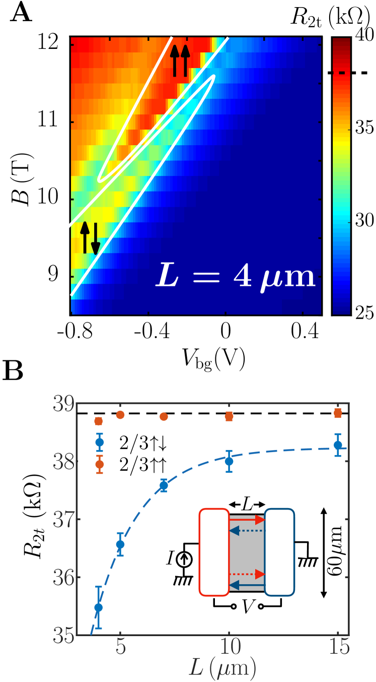
Measuring the evolution of and with length we find independent of contact separation (Fig. 2B, orange circles) whereas increases with , approaching the quantized value for =15 m (Fig. 2B, blue circles). Exponential fit of the two-terminal resistance is presented in Fig. 2B (dashed blue line), , where is the resistance at zero distance, is the resistance at infinite distance, is the characteristic equilibration length (see section 2 of (Sup, ) for additional details on Fig. 2B). Moreover, it is worth noting that the resistance is in agreement with the two-terminal resistance predicted for unequilibrated channels proposed in (MacDonald, 1990), . These observation might have been possible at short distance due to the reduction of scattering events and the screening of the Coulomb interraction by the back gate placed m away from the 2DEG.
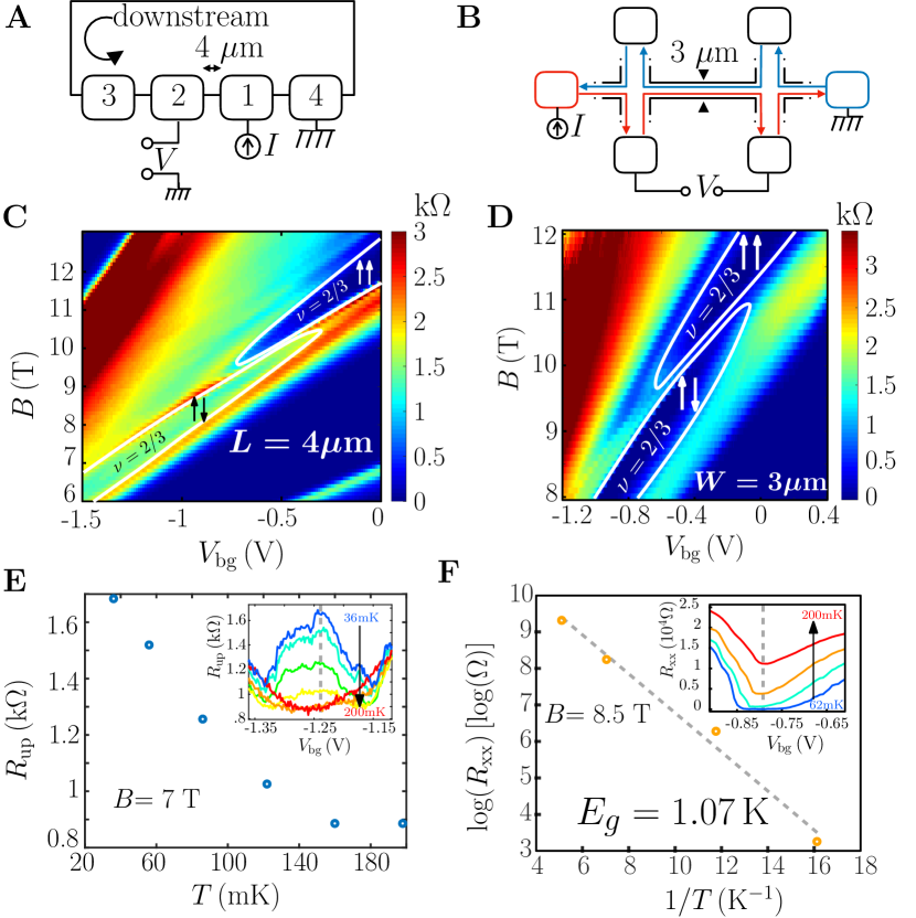
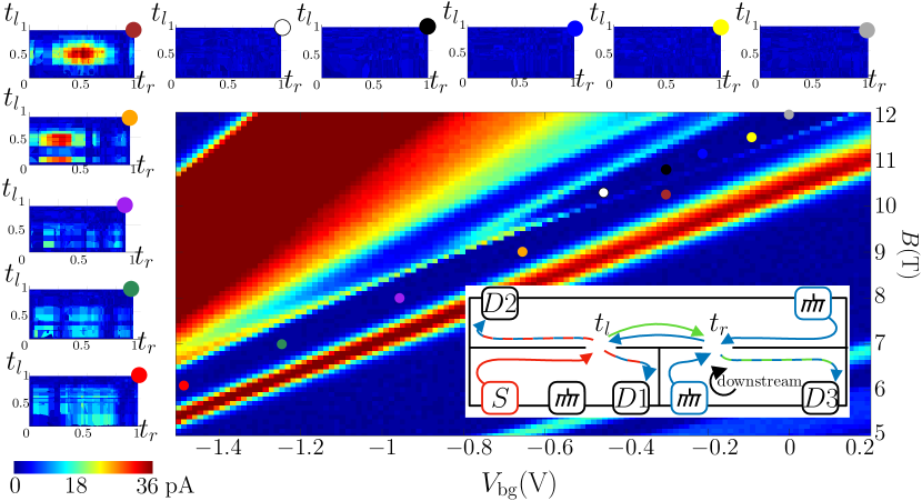
Bearing in mind that a finite caused by dissipation processes at short contact separation can lead to similar observations, a few additional configurations were tested. One of them was a configuration that employs a complementary Hall bar structure, with a narrow Hall channel width of m (Fig. 3B); this was necessary in order to ensure the lack of backscattering along distances under consideration. The measured (Fig. 3D) for the two states using this geometry was negligibly small ensuring that edge states located on opposite sides of the Hall bar (red and blue lines on Fig. 3B) do not exchange particles. This observation is in agreement with the relatively large gap (1 K for the unpolarized state) extracted from the temperature evolution of presented on Fig. 3F, and in agreement with previous measurements (Engel et al., 1992; Boebinger et al., 1985). Furthermore, testing a Corbino geometry sample ensured a negligible bulk conductance of both states (see section 3 of (Sup, )). Finally, a three-terminal configuration, with contacts aligned on a single edge of the mesa (each separated by 4 m), allowed to separate the upstream current from the downstream one (Fig. 3A), providing a direct measurement for the upstream conductance. Current was sourced via contact 1 and drained via contact 4 to the ground. A finite voltage was measured at contact 2 for the unpolarized state only as visible on Fig. 3C. The resistance, defined as , continuously dropped with increasing temperature up to 200 mK (Fig. 3E). This dependence has an opposite trend to that of usual dissipative processes such as variable range hopping or activation mechanisms, ruling them out as alternative explanations. A complementary measurement of the downstream resistance, , was done by sourcing current via contact 2 and measuring the voltage at contact 1. The upstream and downstream conductances, calculated using the Landauer - Buttiker formalism (Büttiker, 1986; Datta, 1995) (see section 4 of (Sup, )), leads to and or equivalent to a two-terminal resistance , in agreement with the two-terminal configuration at 4 m presented above (in Fig. 2). The mobility of the 2DEG in proximity to an alloyed ohmic contact is degraded and its density is increased, which limited us on the minimal distance between ohmic contacts to 4 m. In order to probe the edge modes at shorter distances we employed a configuration consisting of two, gate defined quantum point contacts (QPCs) separated by 700 nm shown in Fig. 4, inset, with all ohmic contacts placed far away (above ). A current nA was sourced via contact ; currents were monitored at the drains while scanning the transmissions of the left and right QPCs and . This was done at different points in the (, ) phase space for both spin polarization of the states, indicated by the colored circles in Fig. 4. In the polarized state, all of the current flowed to drains and independent of , consistent with downstream channels and zero current was measured at (white, black, blue, yellow and gray points in Fig. 4). However, in the unpolarized state (red, green, purple, orange and brown points in Fig. 4), substantial signal was found in , simultaneously decreasing the current measured in and result in overall current conservation (see section 5 of (Sup, )). This ‘upstream effect’ can be explained by the appearance of an upstream current between the two QPCs (green arrow in Fig. 4 inset), which emerges from the left QPC, flows a short distance to the right QPC, and scatters back to the downstream channel, finally arriving at D3. Interestingly, a maximum current at was measured when (a toy model for this effect is presented in Section 6 of (Sup, )).
The present set of experiments revealed counter-propagation of charged particles in the fractional quantum Hall effect regime. This present experiment may induce future theoretical works of the less understood unpolarized state.
Acknowledgements: We thank Ady Stern and Yigal Meir for fruitful discussions. We would like to thank Diana Mahalu for her precious help in the ebeam lithography process. Funding: We acknowledge the European Research Council under the European Community’s Seventh Framework Program, grant agreement number 339070, the partial support of the Minerva Foundation, grant number 711752, and, together with V.U., the German Israeli Foundation (GIF), grant number I-1241-303.10/2014, and the Israeli Science Foundation (ISF). Author contributions: F.L. and A.R. contributed equally to this work in sample design, device fabrication, measurement set-up, data acquisition, data analysis and interpretation, and writing of the paper. M.H. guided the experimental work and contributed in data interpretation and writing of the paper. V.U. contributed in molecular beam epitaxy growth. Competing interests: The authors declare that they have no competing financial interests. Data and materials availability: All data needed to evaluate the conclusions in the paper are present in the paper or the supplementary materials. Additional data will be provided upon reasonable request to the corresponding author.
References
- Klitzing et al. (1980) K. V. Klitzing, G. Dorda, and M. Pepper, Physical Review Letters 45, 494 (1980).
- Tsui et al. (1982) D. C. Tsui, H. L. Stormer, and A. C. Gossard, Physical Review Letters 48, 1559 (1982).
- Laughlin (1983) R. B. Laughlin, Physical Review Letters 50, 1395 (1983).
- Beenakker (1990) C. W. J. Beenakker, Physical Review Letters 64, 216 (1990).
- Wen (1991) X. Wen, Modern Physics Letters B 05, 39 (1991).
- MacDonald (1990) A. H. MacDonald, Physical Review Letters 64, 220 (1990).
- Ashoori et al. (1992) R. C. Ashoori, H. L. Stormer, L. N. Pfeiffer, K. W. Baldwin, and K. West, Physical Review B 45, 3894 (1992).
- Sabo et al. (2017) R. Sabo, I. Gurman, A. Rosenblatt, F. Lafont, D. Banitt, J. Park, M. Heiblum, Y. Gefen, V. Umansky, and D. Mahalu, Nature Physics (2017), 10.1038/nphys4010.
- Kane et al. (1994) C. L. Kane, M. P. A. Fisher, and J. Polchinski, Physical Review Letters 72, 4129 (1994).
- Meir (1994) Y. Meir, Physical Review Letters 72, 2624 (1994).
- (11) J. Wang, Y. Meir, and Y. Gefen, 10.1103/PhysRevLett.111.246803.
- Bid et al. (2010) A. Bid, N. Ofek, H. Inoue, M. Heiblum, C. L. Kane, V. Umansky, and D. Mahalu, Nature 466, 585 (2010).
- Gurman et al. (2012) I. Gurman, R. Sabo, M. Heiblum, V. Umansky, and D. Mahalu, Nature Communications 3, 1289 (2012).
- Inoue et al. (2014) H. Inoue, A. Grivnin, Y. Ronen, M. Heiblum, V. Umansky, and D. Mahalu, Nature Communications 5 (2014), 10.1038/ncomms5067.
- Rosenblatt et al. (2017) A. Rosenblatt, F. Lafont, I. Levkivskyi, R. Sabo, I. Gurman, D. Banitt, M. Heiblum, and V. Umansky, Nature communications 8, 2251 (2017).
- Grivnin et al. (2014) A. Grivnin, H. Inoue, Y. Ronen, Y. Baum, M. Heiblum, V. Umansky, and D. Mahalu, Phys. Rev. Lett. 113, 266803 (2014).
- Eisenstein et al. (1990) J. P. Eisenstein, H. L. Stormer, L. N. Pfeiffer, and K. W. West, Physical Review B 41, 7910 (1990).
- Kronmüller et al. (1998) S. Kronmüller, W. Dietsche, J. Weis, K. von Klitzing, W. Wegscheider, and M. Bichler, Physical Review Letters 81, 2526 (1998).
- Kronmüller et al. (1999) S. Kronmüller, W. Dietsche, K. v. Klitzing, G. Denninger, W. Wegscheider, and M. Bichler, Physical Review Letters 82, 4070 (1999).
- Chakraborty (2000) T. Chakraborty, Advances in Physics 49, 959 (2000).
- Smet et al. (2001a) J. H. Smet, R. A. Deutschmann, W. Wegscheider, G. Abstreiter, and K. von Klitzing, Physical Review Letters 86, 2412 (2001a).
- (22) S. Kraus, O. Stern, J. G. S. Lok, W. Dietsche, K. Von Klitzing, M. Bichler, D. Schuh, and W. Wegscheider, 21, 10.1103/PhysRevLett.89.266801.
- Hayakawa et al. (2012) J. Hayakawa, K. Muraki, and G. Yusa, Nature Nanotechnology 8, 31 (2012).
- Moore et al. (2017) J. N. Moore, J. Hayakawa, T. Mano, T. Noda, and G. Yusa, Phys. Rev. Lett. 118, 076802 (2017).
- Mong et al. (2014) R. S. K. Mong, D. J. Clarke, J. Alicea, N. H. Lindner, P. Fendley, C. Nayak, Y. Oreg, A. Stern, E. Berg, K. Shtengel, and M. P. A. Fisher, Physical Review X 4 (2014), 10.1103/PhysRevX.4.011036, arXiv:1307.4403 .
- Clarke et al. (2014) D. J. Clarke, J. Alicea, and K. Shtengel, Nature Physics 10, 877 (2014), arXiv:1312.6123 .
- Wu et al. (2018) T. Wu, Z. Wan, A. Kazakov, Y. Wang, G. Simion, J. Liang, K. W. West, K. Baldwin, L. N. Pfeiffer, Y. Lyanda-Geller, and L. P. Rokhinson, Phys. Rev. B 97, 245304 (2018).
- Jain (1989) J. K. Jain, Physical Review Letters 63, 199 (1989).
- Kukushkin et al. (1999) I. V. Kukushkin, K. V. Klitzing, and K. Eberl, 82 (1999).
- Verdene et al. (2007) B. Verdene, J. Martin, G. Gamez, J. Smet, K. von Klitzing, D. Mahalu, D. Schuh, G. Abstreiter, and A. Yacoby, Nature Physics 3, 392 (2007).
- Smet et al. (2001b) J. H. Smet, R. A. Deutschmann, W. Wegscheider, G. Abstreiter, and K. Von Klitzing, Physical Review Letters 86, 2412 (2001b).
- Huels et al. (2004) J. Huels, J. Weis, J. Smet, K. Klitzing, and Z. Wasilewski, Physical Review B 69, 085319 (2004).
- Hennel et al. (2016) S. Hennel, B. A. Braem, S. Baer, L. Tiemann, P. Sohi, D. Wehrli, A. Hofmann, C. Reichl, W. Wegscheider, C. Rössler, T. Ihn, K. Ensslin, M. S. Rudner, and B. Rosenow, Phys. Rev. Lett. 116, 136804 (2016).
- Cho et al. (1998) H. Cho, J. B. Young, W. Kang, K. L. Campman, A. C. Gossard, M. Bichler, and W. Wegscheider, Phys. Rev. Lett. 81, 2522 (1998).
- Li et al. (2012) Y. Q. Li, V. Umansky, K. von Klitzing, and J. H. Smet, Phys. Rev. B 86, 115421 (2012).
- Smet et al. (2002) J. H. Smet, R. A. Deutschmann, F. Ertl, W. Wegscheider, G. Abstreiter, and K. von Klitzing, Nature 415, 281 (2002).
- Wu et al. (2012) Y.-H. Wu, G. J. Sreejith, and J. K. Jain, Phys. Rev. B 86, 115127 (2012).
- (38) Supplementary Materials.
- Engel et al. (1992) L. W. Engel, S. W. Hwang, T. Sajoto, D. C. Tsui, and M. Shayegan, Physical Review B 45, 3418 (1992).
- Boebinger et al. (1985) G. S. Boebinger, A. M. Chang, H. L. Stormer, and D. C. Tsui, Physical Review Letters 55, 1606 (1985).
- Büttiker (1986) M. Büttiker, Physical Review Letters 57, 1761 (1986).
- Datta (1995) S. Datta, Cambridge University Press, Vol. 3 (1995) p. 377.