Chiral Phonon Transport Induced by Topological Magnons
Abstract
The plethora of recent discoveries in the field of topological electronic insulators has inspired a search for boson systems with similar properties. There are predictions that ferromagnets on a two-dimensional honeycomb lattice may host chiral edge magnons. In such systems, we theoretically study how magnons and phonons couple. We find topological magnon-polarons around the avoided crossings between phonons and topological magnons. Exploiting this feature along with our finding of Rayleigh-like edge phonons in armchair ribbons, we demonstrate the existence of chiral edge modes with a phononic character. We predict that these modes mediate a chirality in the coherent phonon response and suggest measuring this effect via elastic transducers. These findings reveal a possible approach towards heat management in future devices.
Introduction.— Topological electronic insulators Haldane (1988); Kane and Mele (2005a, b); Bernevig et al. (2006); Hasan and Kane (2010) are characterized by an insulating bulk with conducting ‘chiral’ edge states. The unidirectional propagation of these chiral modes is ‘topologically protected’ against defects at low temperatures when we can disregard inelastic scattering from phonons Hasan and Kane (2010). This has led to the development of a wide range of essential concepts, including Majorana modes Beenakker (2013); Alicea (2012); Mourik et al. (2012); Fu and Kane (2008), topological quantum computation Nayak et al. (2008); Das Sarma et al. (2005), and chiral transport. Inspired by these findings, there has been an upsurge of efforts towards finding similar states in other systems Jotzu et al. (2014) with an emphasis on bosonic excitations Lannebère and Silveirinha (2018); Liu et al. (2017a); Owerre (2016a, b); Kim et al. (2016); Owerre and Nsofini (2017); Kim and Kee (2017). There are predictions of topological magnons Owerre (2016a, b); Kim et al. (2016) in honeycomb ferromagnets with an engineered Dzyaloshinskii-Moriya interaction Dzyaloshinsky (1958); Moriya (1960) that induces the necessary band gap. In contrast to fermionic systems with Fermi energy within this band gap, the bulk is not necessarily insulating in bosonic systems Rückriegel et al. (2018).
The field of magnonics Kruglyak et al. (2010); Chumak et al. (2015); Bauer et al. (2012); Uchida et al. (2010) focuses on pure spin transport mediated by magnons Akhiezer et al. (1968). It is possible to exploit the low-dissipation and wave-like nature of these excitations in information processing Chumak et al. (2014); Ganzhorn et al. (2016). The coherent pumping of chiral surface spin wave (Damon-Eshbach) modes induces cooling via incoherent magnon-phonon scattering An et al. (2013). Besides application oriented properties, the bosonic nature of magnons, combined with spintronic manipulation techniques Saitoh et al. (2006); Chumak et al. (2015), allows for intriguing physics Sonin (2010); Takei et al. (2014); Kamra and Belzig (2016); Kamra et al. (2017). The coupling Kittel (1949) between magnons and phonons fundamentally differs from the electron-phonon interaction and results in a coherent hybridization of the modes Kittel (1958), in addition to the temperature dependent incoherent effects Uchida et al. (2011); An et al. (2013) discussed above. The direct influence of the hybridization between magnons and phonons, known as magnon-polarons Kamra et al. (2015); Kamra and Bauer (2014), has been observed in spin and energy transport in magnetic systems Weiler et al. (2012); Dreher et al. (2012); Flebus et al. (2017); Kikkawa et al. (2016); Bozhko et al. (2017); Rückriegel et al. (2014).
In this Letter, we address the robustness of the topological magnons in a honeycomb ferromagnet Owerre (2016a, b); Kim et al. (2016) against their coupling with the lattice vibrations. In contrast to the case of electron-phonon coupling, where phonons can be disregarded at low temperatures, the magnon dispersion may undergo significant changes with new states emerging in the band gap Bozhko et al. (2017); Rückriegel et al. (2014). We find that in the honeycomb ferromagnet with spins oriented orthogonal to the lattice plane, only transverse phonon modes with out-of-plane displacement couple to spin. To understand the eigenmodes, we evaluate and analyze the coupled spin and out-of-plane phonon modes for an infinitely large plane as well as for a finite ribbon geometry. We quantify the effect of the magneto-elastic coupling on the magnon Hall conductivity and find a non-monotonic dependence on the coupling strength. Our analysis of the finite ribbons shows that topological magnons hybridize with bulk phonons around the avoided crossings in their coupled dispersion, forming magnon-polarons with topological chiral properties. Hence, while their edge localization is weakened, the magneto-elastic coupling does not completely remove the topological magnons. Furthermore, we find that armchair edges support Rayleigh-like edge phonon modes in sharp contrast to the zigzag edges. When topological magnons hybridize with these edge phonons, edge magnon-polarons with almost undiminished chirality are formed. We suggest a setup which utilizes this induced chirality in coherent phonon transport. Such systems enable the observation of the topological physics and serve as a prototype for a unidirectional heat pump. This offers a highly feasible alternative to producing topological phonon diodes Li et al. (2012); Maldovan (2013); Liu et al. (2017b).
Model.—We consider a ferromagnetic material with localized spins on a two-dimensional honeycomb lattice, allow for out-of-plane vibrations of the lattice sites, and assume there is magneto-elastic coupling. This system can be modelled by a Hamiltonian of the form , where is the magnetic Hamiltonian, describes the phonons, and represents the magneto-elastic coupling.
The Hamiltonian we consider is inspired by the Haldane model Haldane (1988) given by Owerre (2016a, b); Kim et al. (2016)
| (1) |
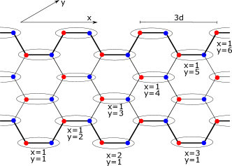
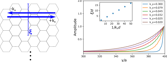
The first term describes the ferromagnetic exchange coupling between nearest neighbour sites, while the second accounts for the Dzyaloshinskii-Moriya interaction Dzyaloshinsky (1958); Moriya (1960) between next-to-nearest neighbours 111The demagnetization energy is disregarded since it only causes minor shifts in the dispersion Kamra et al. (2017).. The Haldane sign depends on the relative orientation of the next-to-nearest neighbours as shown in Fig. 1(a), and is the root of non-trivial topological properties. We let the nearest neighbour distance be and the next-to-nearest neighbour distance be . Refs. Owerre (2016b); Kim et al. (2016) discuss the dispersion relation and Berry curvature of this spin model in linear spin wave theory.
For the phonon Hamiltonian, we consider only the out-of-plane degrees of freedom since only these modes couple to the spin to lowest order in the linear spin wave expansion. We assume nearest-neighbour interactions with elastic constant , let the mass associated with the spins on the lattice sites be , and disregard substrate coupling. Introducing , where the sum is over the three next-to-nearest neighbour vectors of Fig. 1(a), we obtain the dispersion relation
| (2) |
for the free phonon modes.
Motivated by the continuum limit description Kittel (1949, 1958), we write down the lattice magneto-elastic coupling to linear order in the magnon amplitude, obtaining
| (3) |
where parametrizes the strength of the magnon-phonon coupling, denotes the sum over sublattices, is the sum over the lattice sites on the sublattice, and are the corresponding nearest neighbour vectors. The out-of-plane deviation for lattice site is denoted by .
Bulk spectrum.—We introduce the Holstein-Primakoff representation of spins and use linear spin wave theory in the spin- and magneto-elastic terms Akhiezer et al. (1968). Within the rotating wave approximation Scully and Zubairy (1997), the resulting Hamiltonian describing the phonon and magnon modes of the system is obtained as , where . Here, and are annihilation operators for the sublattice magnon modes on the and sublattices, while are the annihilation operators for the phonon modes. The matrix takes the form
| (4) |
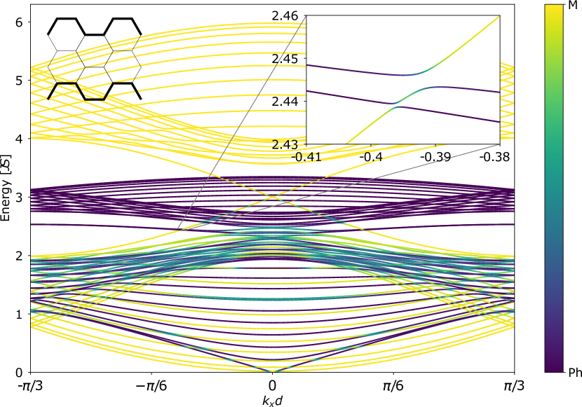
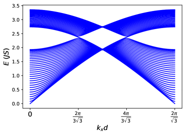
where , , , and . The coupling between the -sublattice magnons and the phonon branch is captured by , which is proportional to the dimensionless coupling strength . The spectrum obtained by diagonalizing this matrix is plotted in Fig. 1(c) along the paths displayed in Fig. 1(b).

Hall conductivity.—The topological nature of the spin model is manifested in the magnon Hall conductivity that arises because of the time-reversal symmetry breaking caused by the Dzyaloshinskii-Moriya interaction.
The spin current operator may be found from a continuity equation or magnon group velocity approach Nakata et al. (2017), both yielding
| (5) |
along the Cartesian direction . Here, is the matrix representation of the magnon Hamiltonian. Assuming we apply a weak in-plane magnetic field gradient , we are interested in the current , which is determined by the conductivity tensor Nakata et al. (2017). The Hall conductivity can be calculated using the Kubo formula, giving
| (6) |
where is the energy eigenvalue of band and is the corresponding Bose factor. The curvature-tensor is given by
| (7) |
where are band-indices, and are the energy eigenstate matrix elements of the current operator at quasimomentum . Disregarding the magneto-elastic coupling, the band-curvature can be identified as the Berry curvature.
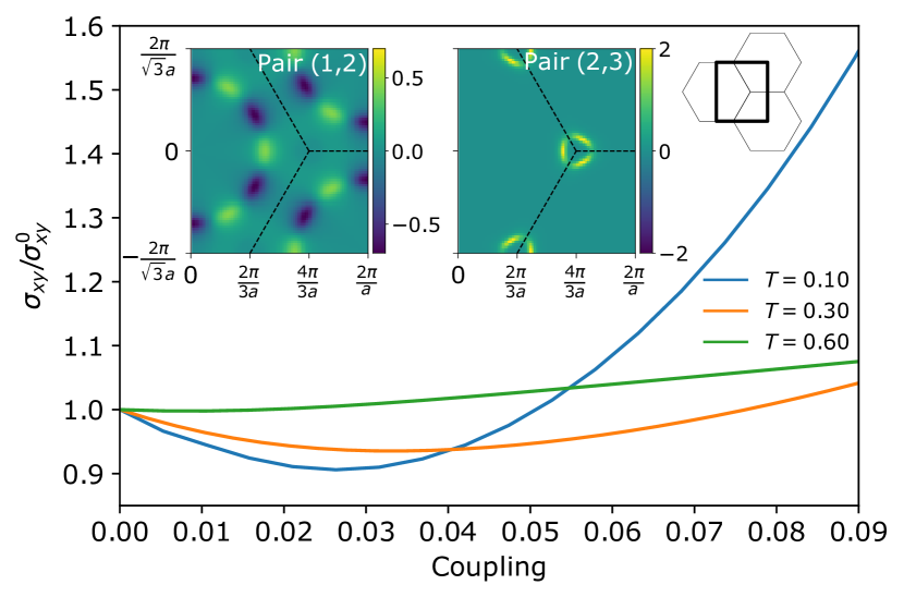
Expressing the sublattice magnon operators in terms of the eigenmode operators, one may identify the current matrix elements and integrate the curvature over the Brillouin zone to obtain the Hall conductivity. We are particularly interested in the effect of the magneto-elastic coupling, and therefore present the dependence of the Hall conductivity on the dimensionless coupling in Fig 2.
To understand this dependence, we consider the curvature-tensor . When the bands and both have a predominant magnon content, the topological nature of the underlying magnons gives a finite curvature. This magnon curvature is largest close to the Dirac points Owerre (2016b); Kim et al. (2016). Close to an avoided crossing, the magneto-elastic coupling changes the spectrum and causes transfer of band-curvature between the relevant bands and . The latter can be seen by plotting the curvature-tensor element for the band-pairs with avoided crossings, as shown in the insets of Fig 2. The resulting change in Hall conductivity is given by these curvature-tensor elements weighted with the difference between the Bose factors of the relevant bands. This follows from the anti-symmetry property of the curvature-tensor. The two band-pairs in the insets contribute oppositely to the Hall conductivity, and the competition between their curvature transfer explains the non-monotonic behaviour of the Hall conductivity.
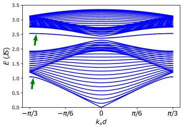
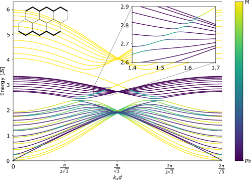
Ribbon geometry and coherent transport.—Due to the topological nature of the magnon model under consideration and the bulk-boundary correspondence, there are gapless magnon edge states in a finite sample Hasan and Kane (2010); Owerre (2016a, b); Kim et al. (2016). Considering an armchair ribbon with finite width, the one-dimensional projection of the energy spectrum is plotted in Fig. 3. The corresponding spectrum for the zigzag edge ribbon is given in the Supplemental Material sup , where also Refs. Kittel (1987); Kino (1987); Maradudin and Stegeman (1991); Bernevig and Hughes ; Ruello and Gusev (2015) appear. Magnon and phonon modes hybridize in regions with an avoided crossing. When the upper phonon band lies within the bandgap of the pure magnon spectrum, there are modes with a mixed content of chiral magnon edge states and phonons. Although the spectra look qualitatively similar, there is a crucial distinction between the two cases. For the zigzag edge configuration, all the phonon modes are delocalized throughout the sample, while the armchair edges host “Rayleigh-like” edge phonon modes. In direct analogy with Rayleigh modes on the surface of a three-dimensional material, the localization length of these modes is directly proportional to their wavelength, as shown in the Supplemental Material sup . These edge phonon modes are supported by the half-hexagon protrusions of the armchair edge that can pivot around the bonds parallel to the edges connecting these protrusions, see Fig. 3. No such parallel bonds exist for the zigzag edge.
The Hall conductivity is a hallmark of topological electronic properties and motivates a similar role for the Hall conductivity mediated by topological magnons. However, in contrast to electrons, the bosonic nature of the magnons results in the lack of a general proportionality between the magnon Hall conductivity and the Chern number Nakata et al. (2017). Furthermore, the observation of a magnon planar Hall effect Liu et al. (2017c) in a cubic, non-topological magnet suggests that this Hall conductivity may not be regarded as a smoking-gun signature for topological properties. Thus, we suggest a complementary approach to observe the topological nature of the underlying magnons by elastically probing the chirality of the magneto-elastic hybrid modes.
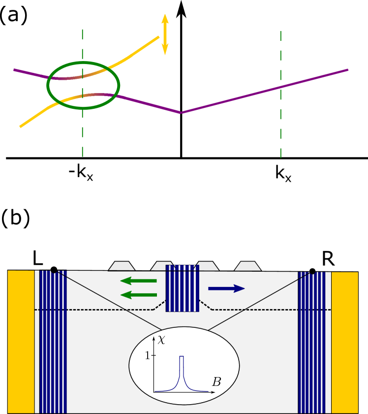
We propose to observe coherent chiral phonon propagation in the experimental setup of Fig. 4(b) by utilizing the edge modes, as depicted schematically in Fig. 4(a) 222The inset of Fig. 3(b) shows two phonon modes. One is irrelevant since it is localized on the opposite edge., on the upper armchair edge of the sample. Taking inspiration from previous related experiments Weiler et al. (2012); Gowtham et al. (2015), we suggest to inject elastic energy into the sample middle at the upper edge using a nano-scale variant of the interdigital transducer design Datta (1986); Mamishev et al. (2004), elaborated further in the Supplemental Material sup . For a given transducer design, modes are excited with fixed wavevectors and a tunable frequency. Similar transducers can be used to detect the elastic response on the left (L) and right (R) edges of the sample. Here, is the elastic power detected at the transducers.
Figure 4(a) schematically depicts the dispersion for the magnetoelastic modes localized on an armchair edge. Disregarding magnetoelastic coupling, the edge hosts two counterpropagating Rayleigh-like edge phonons and a single chiral edge magnon. There is thus no chirality in the phononic response. Due to magnetoelastic coupling, the Rayleigh-like phonon with wavevector hybridizes with the chiral magnon to form a magnon-polaron while the other phonon remains unchanged. This breaks the symmetry between the counterpropagating phononic modes and the result is non-zero chirality . Furthermore, as shown in Fig. 4(a), the hybridization with the magnon mode reverses the group velocity direction of the participating phonon mode. In principle, this gives perfectly chiral phonon transport.
The wavevector location of the avoided crossing can be tuned via the Zeeman shift in the magnon dispersion. Performing a frequency integrated measurement over an energy range of the same order as the magneto-elastic coupling, one obtains a peaked chirality when the magnetic field is such that the wavevector of the avoided crossing coincides with the wavevector of the transducer, obtaining a chirality as shown in Fig. 4(b). Performing a similar transport experiment on the zigzag edge does not give chiral phonon transport since the delocalized phonons hybridize with counterpropagating magnons on both the edges, thereby destroying the overall chirality. In addition, the size of the avoided crossing is smaller due to the smaller overlap with the localized chiral magnon. The armchair edge is therefore crucial for obtaining the chirality.
Summary.— We have examined the robustness of topological magnons in a honeycomb ferromagnet against their interaction with phonons. Their topological properties, albeit weakened, survive the magneto-elastic coupling. The magnon Hall conductivity of the system is found to depend on the magneto-elastic coupling strength in a non-monotonic, temperature-sensitive manner. Exploiting the Rayleigh-like edge phonons in armchair ribbons, we predict the existence of topological magnon-polarons confined to the boundary. We have suggested an experimental setup capable of probing the chiral nature of the topological magnon-polarons by elastic means, which thus serves as a platform for chiral coherent phononic transport.
Acknowledgments.—We acknowledge support from the Research Council of Norway Grant Nos. 262633 “Center of Excellence on Quantum Spintronics”, and 250985, “Fundamentals of Low-dissipative Topological Matter”.
References
- Haldane (1988) F. D. M. Haldane, “Model for a quantum hall effect without landau levels: Condensed-matter realization of the ”parity anomaly”,” Phys. Rev. Lett. 61, 2015–2018 (1988).
- Kane and Mele (2005a) C. L. Kane and E. J. Mele, “ topological order and the quantum spin hall effect,” Phys. Rev. Lett. 95, 146802 (2005a).
- Kane and Mele (2005b) C. L. Kane and E. J. Mele, “Quantum spin hall effect in graphene,” Phys. Rev. Lett. 95, 226801 (2005b).
- Bernevig et al. (2006) B. Bernevig, T. L. Hughes, and S.-C. Zhang, “Quantum spin hall insulator state in hgte quantum wells,” Science 314, 1757–1761 (2006).
- Hasan and Kane (2010) M. Z. Hasan and C. L. Kane, “Colloqium: Topological insulators,” Rev. Mod. Phys. 82, 3045–3067 (2010).
- Beenakker (2013) C.W.J. Beenakker, “Search for majorana fermions in superconductors,” Annual Review of Condensed Matter Physics 4, 113–136 (2013), https://doi.org/10.1146/annurev-conmatphys-030212-184337 .
- Alicea (2012) Jason Alicea, “New directions in the pursuit of majorana fermions in solid state systems,” Reports on Progress in Physics 75, 076501 (2012).
- Mourik et al. (2012) V. Mourik, K. Zuo, S. M. Frolov, S. R. Plissard, E. P. A. M. Bakkers, and L. P. Kouwenhoven, “Signatures of majorana fermions in hybrid superconductor-semiconductor nanowire devices,” Science 336, 1003–1007 (2012), http://science.sciencemag.org/content/336/6084/1003.full.pdf .
- Fu and Kane (2008) Liang Fu and C. L. Kane, “Superconducting proximity effect and majorana fermions at the surface of a topological insulator,” Phys. Rev. Lett. 100, 096407 (2008).
- Nayak et al. (2008) Chetan Nayak, Steven H. Simon, Ady Stern, Michael Freedman, and Sankar Das Sarma, “Non-abelian anyons and topological quantum computation,” Rev. Mod. Phys. 80, 1083–1159 (2008).
- Das Sarma et al. (2005) Sankar Das Sarma, Michael Freedman, and Chetan Nayak, “Topologically protected qubits from a possible non-abelian fractional quantum hall state,” Phys. Rev. Lett. 94, 166802 (2005).
- Jotzu et al. (2014) Gregor Jotzu, Michael Messer, Rémi Desbuquois, Martin Lebrat, Thomas Uehlinger, Daniel Greif, and Tilman Esslinger, “Experimental realization of the topological haldane model with ultracold fermions,” Nature 515, 237 EP – (2014).
- Lannebère and Silveirinha (2018) Sylvain Lannebère and Mário G. Silveirinha, “Link between the photonic and electronic topological phases in artificial graphene,” Phys. Rev. B 97, 165128 (2018).
- Liu et al. (2017a) Yizhou Liu, Yong Xu, Shou-Cheng Zhang, and Wenhui Duan, “Model for topological phononics and phonon diode,” Phys. Rev. B 96, 064106 (2017a).
- Owerre (2016a) S A Owerre, “A first theoretical realization of honeycomb topological magnon insulator,” Journal of Physics: Condensed Matter 28, 386001 (2016a).
- Owerre (2016b) S. A. Owerre, “Topological honeycomb magnon hall effect: A calculation of thermal hall conductivity of magnetic spin excitations,” Journal of Applied Physics 120, 043903 (2016b), https://doi.org/10.1063/1.4959815 .
- Kim et al. (2016) Se Kwon Kim, Héctor Ochoa, Ricardo Zarzuela, and Yaroslav Tserkovnyak, “Realization of the haldane-kane-mele model in a system of localized spins,” Phys. Rev. Lett. 117, 227201 (2016).
- Owerre and Nsofini (2017) S A Owerre and J Nsofini, “Squeezed dirac and topological magnons in a bosonic honeycomb optical lattice,” Journal of Physics: Condensed Matter 29, 455802 (2017).
- Kim and Kee (2017) Heung-Sik Kim and Hae-Young Kee, “Realizing haldane model in fe-based honeycomb ferromagnetic insulators,” npj Quantum Materials 2, 20 (2017).
- Dzyaloshinsky (1958) I. Dzyaloshinsky, “A thermodynamic theory of “weak” ferromagnetism of antiferromagnetics,” Journal of Physics and Chemistry of Solids 4, 241 – 255 (1958).
- Moriya (1960) Tôru Moriya, “Anisotropic superexchange interaction and weak ferromagnetism,” Phys. Rev. 120, 91–98 (1960).
- Rückriegel et al. (2018) Andreas Rückriegel, Arne Brataas, and Rembert A. Duine, “Bulk and edge spin transport in topological magnon insulators,” Phys. Rev. B 97, 081106 (2018).
- Kruglyak et al. (2010) V V Kruglyak, S O Demokritov, and D Grundler, “Magnonics,” Journal of Physics D: Applied Physics 43, 264001 (2010).
- Chumak et al. (2015) A. V. Chumak, V. I. Vasyuchka, A. A. Serga, and B. Hillebrands, “Magnon spintronics,” Nat Phys 11, 453 (2015).
- Bauer et al. (2012) Gerrit E. W. Bauer, Eiji Saitoh, and Bart J. van Wees, “Spin caloritronics,” Nat Mater 11, 391 (2012).
- Uchida et al. (2010) K. Uchida, J. Xiao, H. Adachi, J. Ohe, S. Takahashi, J. Ieda, T. Ota, Y. Kajiwara, H. Umezawa, H. Kawai, G. E. W. Bauer, S. Maekawa, and E. Saitoh, “Spin seebeck insulator,” Nat Mater 9, 894–897 (2010).
- Akhiezer et al. (1968) A.I. Akhiezer, V.G. Bar’iakhtar, and S.V. Peletminski, Spin waves (North-Holland Publishing Company, Amsterdam, 1968).
- Chumak et al. (2014) Andrii V. Chumak, Alexander A. Serga, and Burkard Hillebrands, “Magnon transistor for all-magnon data processing,” Nature Communications 5, 4700 (2014).
- Ganzhorn et al. (2016) Kathrin Ganzhorn, Stefan Klingler, Tobias Wimmer, Stephan Geprägs, Rudolf Gross, Hans Huebl, and Sebastian T. B. Goennenwein, “Magnon-based logic in a multi-terminal yig/pt nanostructure,” Applied Physics Letters 109, 022405 (2016), https://doi.org/10.1063/1.4958893 .
- An et al. (2013) T. An, V. I. Vasyuchka, K. Uchida, A. V. Chumak, K. Yamaguchi, K. Harii, J. Ohe, M. B. Jungfleisch, Y. Kajiwara, H. Adachi, B. Hillebrands, S. Maekawa, and E. Saitoh, “Unidirectional spin-wave heat conveyer,” Nature Materials 12, 549 (2013).
- Saitoh et al. (2006) E. Saitoh, M. Ueda, H. Miyajima, and G. Tatara, “Conversion of spin current into charge current at room temperature: Inverse spin-hall effect,” Applied Physics Letters 88, 182509 (2006).
- Sonin (2010) E.B. Sonin, “Spin currents and spin superfluidity,” Advances in Physics 59, 181–255 (2010), http://dx.doi.org/10.1080/00018731003739943 .
- Takei et al. (2014) So Takei, Bertrand I. Halperin, Amir Yacoby, and Yaroslav Tserkovnyak, “Superfluid spin transport through antiferromagnetic insulators,” Phys. Rev. B 90, 094408 (2014).
- Kamra and Belzig (2016) Akashdeep Kamra and Wolfgang Belzig, “Super-poissonian shot noise of squeezed-magnon mediated spin transport,” Phys. Rev. Lett. 116, 146601 (2016).
- Kamra et al. (2017) Akashdeep Kamra, Utkarsh Agrawal, and Wolfgang Belzig, “Noninteger-spin magnonic excitations in untextured magnets,” Phys. Rev. B 96, 020411 (2017).
- Kittel (1949) Charles Kittel, “Physical theory of ferromagnetic domains,” Rev. Mod. Phys. 21, 541–583 (1949).
- Kittel (1958) C. Kittel, “Interaction of spin waves and ultrasonic waves in ferromagnetic crystals,” Phys. Rev. 110, 836–841 (1958).
- Uchida et al. (2011) K. Uchida, H. Adachi, T. An, T. Ota, M. Toda, B. Hillebrands, S. Maekawa, and E. Saitoh, “Long-range spin seebeck effect and acoustic spin pumping,” Nat Mater 10, 737 (2011).
- Kamra et al. (2015) Akashdeep Kamra, Hedyeh Keshtgar, Peng Yan, and Gerrit E. W. Bauer, “Coherent elastic excitation of spin waves,” Phys. Rev. B 91, 104409 (2015).
- Kamra and Bauer (2014) Akashdeep Kamra and Gerrit E.W. Bauer, “Actuation, propagation, and detection of transverse magnetoelastic waves in ferromagnets,” Solid State Communications 198, 35 – 39 (2014), sI: Spin Mechanics.
- Weiler et al. (2012) M. Weiler, H. Huebl, F. S. Goerg, F. D. Czeschka, R. Gross, and S. T. B. Goennenwein, “Spin pumping with coherent elastic waves,” Phys. Rev. Lett. 108, 176601 (2012).
- Dreher et al. (2012) L. Dreher, M. Weiler, M. Pernpeintner, H. Huebl, R. Gross, M. S. Brandt, and S. T. B. Goennenwein, “Surface acoustic wave driven ferromagnetic resonance in nickel thin films: Theory and experiment,” Phys. Rev. B 86, 134415 (2012).
- Flebus et al. (2017) Benedetta Flebus, Ka Shen, Takashi Kikkawa, Ken-ichi Uchida, Zhiyong Qiu, Eiji Saitoh, Rembert A. Duine, and Gerrit E. W. Bauer, “Magnon-polaron transport in magnetic insulators,” Phys. Rev. B 95, 144420 (2017).
- Kikkawa et al. (2016) Takashi Kikkawa, Ka Shen, Benedetta Flebus, Rembert A. Duine, Ken-ichi Uchida, Zhiyong Qiu, Gerrit E. W. Bauer, and Eiji Saitoh, “Magnon polarons in the spin seebeck effect,” Phys. Rev. Lett. 117, 207203 (2016).
- Bozhko et al. (2017) Dmytro A. Bozhko, Peter Clausen, Gennadii A. Melkov, Victor S. L’vov, Anna Pomyalov, Vitaliy I. Vasyuchka, Andrii V. Chumak, Burkard Hillebrands, and Alexander A. Serga, “Bottleneck accumulation of hybrid magnetoelastic bosons,” Phys. Rev. Lett. 118, 237201 (2017).
- Rückriegel et al. (2014) Andreas Rückriegel, Peter Kopietz, Dmytro A. Bozhko, Alexander A. Serga, and Burkard Hillebrands, “Magnetoelastic modes and lifetime of magnons in thin yttrium iron garnet films,” Phys. Rev. B 89, 184413 (2014).
- Li et al. (2012) Nianbei Li, Jie Ren, Lei Wang, Gang Zhang, Peter Hänggi, and Baowen Li, “Colloqium: Phononics: Manipulating heat flow with electronic analogs and beyond,” Rev. Mod. Phys. 84, 1045–1066 (2012).
- Maldovan (2013) Martin Maldovan, “Sound and heat revolutions in phononics,” Nature 503, 209 (2013).
- Liu et al. (2017b) Yizhou Liu, Yong Xu, Shou-Cheng Zhang, and Wenhui Duan, “Model for topological phononics and phonon diode,” Phys. Rev. B 96, 064106 (2017b).
- Note (1) The demagnetization energy is disregarded since it only causes minor shifts in the dispersion Kamra et al. (2017).
- Scully and Zubairy (1997) Marlan O. Scully and M. Suhail Zubairy, Quantum optics (Cambridge University Press, Cambridge, 1997).
- Nakata et al. (2017) Kouki Nakata, Jelena Klinovaja, and Daniel Loss, “Magnonic quantum hall effect and wiedemann-franz law,” Phys. Rev. B 95, 125429 (2017).
- (53) See supplemental material.
- Kittel (1987) C. Kittel, Quantum Theory of Solids (John Wiley & Sons, 1987).
- Kino (1987) G.S. Kino, Acoustic Waves: Devices, Imaging, and Analog Signal Processing, Prentice-Hall Contemporary Topics in Accounting Series (Prentice-Hall, 1987).
- Maradudin and Stegeman (1991) A. A. Maradudin and G. I Stegeman, “Surface acoustic waves,” in Surface phonons, edited by F. W. de Wette W. Kress (Springer-Verlag, Berlin-Heidelberg, 1991) Chap. 2, pp. 5–36.
- (57) B. Andrei Bernevig and Taylor L. Hughes, Topological insulators and topological superconductors (Princeton University Press).
- Ruello and Gusev (2015) Pascal Ruello and Vitalyi E Gusev, “Physical mechanisms of coherent acoustic phonons generation by ultrafast laser action,” Ultrasonics 56, 21–35 (2015).
- Liu et al. (2017c) J. Liu, L. J. Cornelissen, J. Shan, T. Kuschel, and B. J. van Wees, “Magnon planar hall effect and anisotropic magnetoresistance in a magnetic insulator,” Phys. Rev. B 95, 140402 (2017c).
- Note (2) The inset of Fig. 3(b) shows two phonon modes. One is irrelevant since it is localized on the opposite edge.
- Gowtham et al. (2015) P. G. Gowtham, T. Moriyama, D. C. Ralph, and R. A. Buhrman, “Traveling surface spin-wave resonance spectroscopy using surface acoustic waves,” Journal of Applied Physics 118, 233910 (2015).
- Datta (1986) S. Datta, Surface acoustic wave devices (Prentice-Hall, 1986).
- Mamishev et al. (2004) Alexander V. Mamishev, Kishore Sundara-Rajan, Fumin Yang, Yanqing Du, and Markus Zahn, “Interdigital sensors and transducers,” Proceedings of the IEEE 92, 808 (2004).
Supplemental Material to the manuscript “Chiral Phonon Transport Induced by Topological Magnons” by
Even Thingstad, Akashdeep Kamra, Arne Brataas, Asle Sudbø
I Rayleigh-like phonon edge modes
To describe the phonons, as discussed in the main paper, we consider a force constant model for out-of-plane phonon modes on the honeycomb lattice with only nearest neighbour interaction. This is described by the Hamiltonian
| (8) |
where and are lattice site indices running over both the and sublattices of the honeycomb lattice.
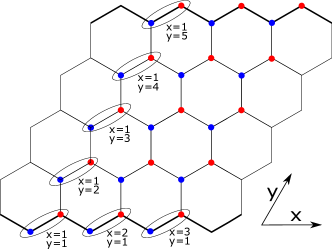
To investigate edge modes in the system, we consider a finite ribbon geometry with periodic boundary conditions in one direction, and with a finite number of unit cells in the other direction. The edges of such ribbons can mainly be of two types: zigzag and armchair. The lattice geometries of these cases are shown in Fig. 5.
To find the phonon energy spectrum for these lattice geometries, we introduce the partial Fourier transform of the lattice site deviations and momenta, which for the lattice site deviation takes the form
| (9) |
where is the lattice site deviation on sublattice in unit cell , is the corresponding equilibrium position, and is the number of unit cells in the horizontal direction. The periodicity requirement then gives , where is the periodicity of the lattice in the horizontal direction and is an integer. For the zigzag edge ribbon, , while for the armchair edge ribbon. This determines the size of the Brillouin zone.
Introducing
| (10) |
with similar notation for the momentum, the phonon Hamiltonian can be written on the form
| (11) |
with a matrix coupling the deviations on the various sublattices and neighbouring unit cell layers. This Hamiltonian is diagonalized through a unitary transform of the deviations and momenta followed by introducing phonon creation and annihilation operators and Kittel (1987). The excitation spectrum is then given by the phonon frequencies , where
and are the eigenvalues of .
Following this procedure for the ribbon geometry with zigzag edges, we obtain the spectrum in Fig. 6(a). The upper and lower branches of the phonon spectrum meet at and , consistent with the result obtained by taking the 1-dimensional projection of the bulk bands. In Fig. 7, we plot the spatial profile of some selected eigenstates at quasimomentum . All the modes are delocalized.
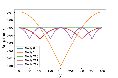
Examining the armchair ribbon spectrum in Fig. 6(b),
one may notice that the modes marked with green arrows stand out from the rest.
If we were to compute the bulk spectrum and then perform a 1D projection, the two modes marked in green would not be found. We therefore conclude that they must originate from an edge effect.
This is confirmed by examining the spatial profile of the modes, as shown in Fig. 8 for the modes between the upper and lower bulk phonon branches. The deviation amplitudes are finite on the outer armchair edges of the sample, and exponentially decaying into the interior of the sample. The inset shows the decay length as function of the inverse quasimomentum, and demonstrates that . This is perfectly analogous to the behaviour of so-called Rayleigh modes on the surface of a three-dimensional material Maradudin and Stegeman (1991). Our modes can therefore be characterized as one-dimensional analogs of Rayleigh modes.
From the above discussion, it follows that that while the armchair edges support edge modes, the zigzag edge does not. This is rooted in the fact that on the edge unit cells of the armchair ribbon, both atoms have 2 nearest neighbours. For the zigzag ribbon, one atom has 2 nearest neighbours, but the other has 3. Vibrations are therefore easier to excite on the edges of the armchair ribbon.
II Coupled magnetoelastic modes in Zigzag ribbon
To compute the excitation spectrum for the model with coupled magnon and phonon modes, we first calculate the phonon and magnon edge modes for the uncoupled model. The phonon modes were discussed in the previous section, and we refer to the literature for the magnon spectrum Bernevig and Hughes . Expressing the magneto-elastic coupling in terms of these eigenmodes and diagonalizing the resulting matrix, we obtain the excitation spectra.
For the zigzag edge ribbon, the spectrum is shown in Fig. 9. All phonon modes are delocalized. In the inset, we show the hybridization of the chiral edge magnon mode with some of these delocalized modes. The armchair ribbon spectrum has already been discussed in the main text.
III Interdigital elastic transducers
III.1 General principles and qualitative description
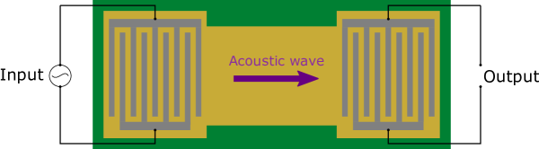
The interdigital transducer Kino (1987); Mamishev et al. (2004) (IDT) consists of two metallic electrodes with a series of sections, called fingers, which are patterned into a comb-like structure on top of a piezoelectric material (Fig. 10). When a voltage is applied across the two electrodes, it creates a pattern of alternating charges on adjacent fingers via the capacitive effect. Via the constitutive properties of the piezoelectric material, this results in a pattern of alternating strains. An applied ac voltage with angular frequency thus excites acoustic waves at the same frequency in the piezoelectric material. The wavelength is determined by the corresponding dispersion relation 333For simplicity, and as a concrete example, we consider the linear dispersion of the Rayleigh waves typical of a conventional IDT system. The technique however works for an arbitrary dispersion ., where is the speed of sound in the material and is the wavenumber. If the ensuing wavelength is equal to the spacing between the adjacent fingers belonging to the same electrode, the acoustic signal interferes constructively and the excitation efficiency is high. If there is a mismatch between the finger spacing and the wavelength excited at the applied ac voltage frequency, the acoustic waves tend to cancel each other and excitation efficiency is low. With an increasing number of fingers, the reinforcement or cancellation effect is stronger and the excitation resonances become sharper. Thus, the operation principle of an IDT is similar to that of a Bragg grating. Then, it is easy to understand that peaks in excitation are observed at multiple frequencies (and wavelengths) corresponding to the finger spacing being multiples of the acoustic wavelength. The fundamental peak is the strongest and subsequent overtones are progressively weaker as demonstrated by the frequency transfer characteristics discussed below.
Conventionally, IDTs have been employed in applications such as analog filters, and their desired operation frequency range has been from MHz to several tens of GHz Kino (1987). A typical piezoelectric material employed is Lithium Niobate with a Rayleigh wave speed of 3.3 kms. Thus, the fundamental peak corresponding to a center frequency of 1 GHz requires finger spacing of around 1 m, which could easily be achieved via photolithography techniques. With contemporary electron-beam lithography techniques, a finger spacing of several tens of nanometers is readily possible, thus allowing a fundamental frequency of tens of GHz. Employing higher overtones allows pushing the operation frequency to several tens of GHz, and is predominantly limited by the driving electronics Mamishev et al. (2004). Due to the purview of their conventional applications, attempts to achieve higher frequencies have been limited. With recent advances in ultrafast lasers, several conventional methods have been adapted to achieve coherent phonon generation in the THz regime Ruello and Gusev (2015). Thus, the operation range of the proposed method is estimated to be rather wide with up to hundreds of GHz in frequency and tens of nanometers in wavelength. The wavenumber selectivity can also be increased, in principle to arbitrary values, by using a large number of fingers. Combined with the tunability of the exact magnon-phonon anticrossing point (via an applied field, for example) across a broad range of frequencies and wavevectors, the proposed experimental method is well within the range of the contemporary state-of-the-art technology.
III.2 Frequency resolved acoustic output
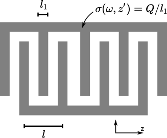
To supplement the above qualitative discussion of the operating principles of an IDT, we now discuss its frequency resolved excitation efficiency within the so-called delta function model (Fig. 11). This model assumes that the charge accumulated on each finger is distributed uniformly and that the acoustic output is a linear superposition of the strain produced by the full charge distribution. In evaluating the strain (and thus the acoustic output) at a given point due to different fingers, the phase difference due to wave propagation from the fingers needs to be accounted adequately. The amplitude of the excited acoustic wave at a position is thus given by
| (12) |
where is the charge-strain coupling factor of the piezoelectric material and is the charge density accumulated at position . The acoustic output of the IDT is thus simply the Fourier transform of the accumulated charge density. The square-wave like pattern of the accumulated charge on the comb-like structure thus suggests a sinc function response.
Referring the readers to detailed derivations and discussion in Ref. Kino, 1987, we simply present the key result here. For an -finger comb, the overall acoustic amplitude outside the IDT region becomes
| (13) |
where is the charge on a single finger, and are defined in Fig. 11, and sinc. The equation above fully describes all the design characteristics of the device. Its further analysis shows that the center or fundamental frequency is determined by the condition (Note that ), while the bandwidth between the zeros in the response is given by , in consistence with the qualitative discussion above.