Microfluidic pump driven by anisotropic phoresis
Abstract
Fluid flow along microchannels can be induced by keeping opposite walls at different temperatures, and placing elongated tilted pillars inside the channel. The driving force for this fluid motion arises from the anisotropic thermophoretic effect of the elongated pillars that generates a force parallel to the walls, and perpendicular to the temperature gradient. The force is not determined by the thermophilic or thermophobic character of the obstacle surface, but by the geometry and the thermophoretic anisotropy of the obstacle. Via mesoscale hydrodynamic simulations, we investigate the pumping properties of the device as a function of the channel geometry, and pillar surface properties. Applications as fluidic mixers, and fluid alternators are also outlined, together with the potential use of all these devices to harvest waste heat energy. Furthermore, similar devices can be also built employing diffusiophoresis or electrophoresis.
I Introduction
Guiding the movement of fluid at nano- and micro-scales has become one of the most challenging goals in the emergent field of microfluidics Whitesides (2006); Martinez et al. (2017). Relevant applications of an efficient design of microfluid pumping are related with drug delivery Nisar et al. (2008); Herrlich et al. (2012), biomedical assays Wang and Fu (2018); Amirouche et al. (2009) and cell culturing Byun et al. (2013). This requires the capability to use minimal quantities of energy to carry fluid with high resolution and sensitivity. In microfluidic devices, fluids are typically transported, separated, or processed along microchannels of different compositions and geometries. The generation of net fluid flows is frequently achieved by applying external mechanical forces with coupled inlet and outlet systems Squires and Quake (2005); Stone et al. (2004); Darhuber and Troian (2005). The efficiency of such driving mechanisms importantly decreases with miniaturization because of the huge increase in hydrodynamic resistance that comes with downsizing Dauparas et al. (2018). Moreover, the fact that in- and outlets rely on external pieces of equipment, importantly hampers the portability of the devices. A competitive approach is to induce stresses localized at the boundaries, through non-mechanical means which are driven typically by local fields Zhou et al. (2016); Michelin et al. (2015); Yang and Ripoll (2016); Paxton et al. (2004); Jewell et al. (2016). This has shown to be especially efficient for miniaturizing fluidic pumps, due to the intrinsic large surface to volume ratio.
Phoretic or the related osmotic properties of solid materials in a fluid solution constitute an attractive option to induce stresses close to confining walls. Phoresis refers to the directed drift motion of a suspended particle induced due to an inhomogeneous surrounding Anderson (1989); Moran and Posner (2017), which can be, for example, a temperature gradient (thermophoresis) Würger (2010); Piazza and Parola (2008); Ganti et al. (2017); Fu et al. (2017), a concentration gradient (diffusiophoresis) Derjaguin et al. (1993); BRADY (2011); Howse et al. (2007) or an electric potential gradient (electrophoresis) Saville (1977); Shendruk et al. (2012); Hickey et al. (2012). Conversely, the gradient can generate the motion of a fluid at a fixed solid-fluid interface, which is usually referred to as phoretic osmosis, and in the case of a fluid-fluid interface, which is known as phoretic capillary Anderson (1989). Catalytic surfaces and related chemical gradients have shown a large potential in microfluidic applications Paxton et al. (2006); Sengupta et al. (2014); Ortiz-Rivera et al. (2016); Das et al. (2017), while thermal gradients are relatively less exploited. Thermal gradient-driven motion has though promising prospectives since it works equally well in charged and neutral solutions, and it is pollution-free due to the absence of surfactants or chemical fuels, which enables the way to bio-compatible applications Duhr et al. (2004); Vigolo et al. (2010); Tsuji et al. (2017). Furthermore, thermal gradient-driven motion allows optical microscale operations with optical heating which is the basic principle of the emerging field of optofluidics Baigl (2012); Namura et al. (2017). So far, existing phoretic fluidics rely on intricate differentiated compositions Kline et al. (2005); Jiang et al. (2010); Liu and Li (2010) or ratchet geometries of channel walls Yang and Ripoll (2014); Yang et al. (2015a); Yang and Ripoll (2016); Maggi et al. (2015). To extend the tunability and functionality of these pumps is therefore timely and highly desirable.
Anisotropic thermophoresis has been recently described opening a new avenue for the design of novel and versatile microdevices Tan et al. (2017); Yang et al. (2014). The anisotropic phoretic effect refers to the different phoretic response that elongated objects, such as colloids or pillars, have when aligned with, or perpendicular to the external gradient. Interestingly, for obstacles with tilted orientation this anisotropy might translate into a force which would not only be aligned with the gradient, as it is in the case of traditional phoresis, but additionally also perpendicular to the gradient. This mechanism has been already employed for the design of microturbines which can rotate unidirectionally Yang et al. (2014). Given the related nature of different phoretic effects, this effect has proved to exist not only for thermohoresis, but also for diffusiophoresis, this is in for example in the presence of multicomponent fluids with catalytic surfaces Yang et al. (2015b).
In this work, we propose a new class of microfluidic pump based on the anisotropic phoretic effect. Instead of considering the asymmetries at the channel walls as in previous devices, we present a micropump exploiting the tunable properties of the immersed solid obstacles with thermophoretic anisotropy in the middle of the channel, which could be engineered for example by means of lithography Tasinkevych et al. (2014); Liu et al. (2013). Opposite walls will have fixed different temperatures, such that the pillars are exposed to a temperature gradient. The phoretic properties of the pillars surface will thus generate a fluid flow along the microchannel, perpendicular to the thermal gradient. The device will have a large versatility due first to factors intrinsic to the anisotropic pump such as pillars geometry, number of obstacles per unit length, or obstacles configuration, the subtle dependence of the phoretic behavior on a large number of factors such as average temperature or pressure, presence of salt, or surface coatings among many others. Also very remarkable will be the case in which the obstacles do not have a fixed orientation with respect to the walls, but can be externally in situ controlled, e.g. by laser tweezers on suspended colloids, such that the flow pattern will become highly adjustable and rich. In addition, the suspended objects may even be removed from and imported into the channel without affecting the channel itself. Furthermore, variations of the microchannel device are shown to work not only as microfluidic pumps with arbitrarily microchannel length, but also as fluidic mixers, or generators of alternating flow. Finally, and given the fact that they work under the effect of external gradients, they all have potential applications to harvest waste thermal or chemical energy.
II Model and mechanism
II.1 Simulation setup
Simulations have been performed by a mesoscale hydrodynamic approach which combines multiple particle collision dynamics (MPC) and molecular dynamics (MD) Malevanets and Kapral (1999, 2000); Kapral (2008); Gompper et al. (2009). MPC is a particle-based model in which a coarse grain solvent is represented by point particles of mass , characterized by continuous positions and velocities (), which evolve in two alternating steps. In the streaming step, particle positions evolve ballistically for a certain time , which we refer to as the collision time. In the collision step, particles are sorted into cubic cells, with cell size , and each particle rotates its relative velocity to the cell center of mass velocity by an angle around a randomly chosen direction. The collisional operation conserves mass, linear momentum and energy at the cell level. The cell-grid is randomly displaced to maintain Galilean invariance Ihle and Kroll (2001) and enhance the fluid like properties of the solvent Ihle and Kroll (2003); Tüzel et al. (2006); Ripoll et al. (2005). Standard simulation units are chosen, , with the averaged temperature, which means for example that time is given in units of , which will be typically not specified. Usual MPC parameters are used, , , and average number of particles per collision box, corresponding to a kinematic viscosity . For direct comparison with real fluids, dimensionless numbers are typically calculated, such as the Schmidt number , or the Prandlt number , which for the specified parameters are and respectively. In this respect shows to be very close to most relevant fluids such as water, although is clearly smaller. While the Prandlt number indicates that the transport of heat and momentum are properly separated in our case, the Schmidt number refers to the separation of mass and momentum, which in our case are less separated than in most fluids. This lower value might be an issue when quantitatively mapping to real units, although is absolutely not a problem to reproduce a fluid with correct liquid-like dynamics Ripoll et al. (2004, 2005). Solid channel walls with stick boundary conditions are realized by applying the bounce-back rule to the solvent particles when reaching the walls, and the temperature gradient is implemented by thermostatting thin solvent layers close to the walls with low and high temperatures Lüsebrink and Ripoll (2012); Yang and Ripoll (2013). The employed default temperature at the no-slip walls are and in MPC units. These could be converted to real units by considering for example an average temperature equal to , corresponding to very high temperature differences, although, as later discussed, this could be compensated with other unit mismatches.
(c)  0.05in-0.1in
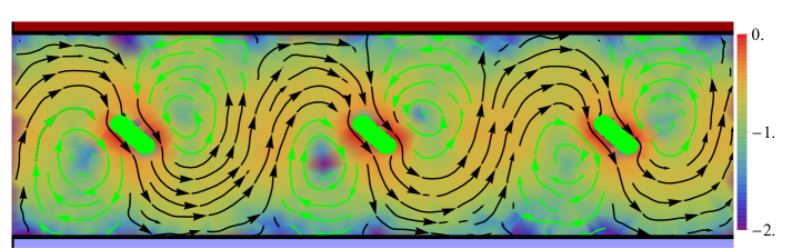
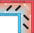
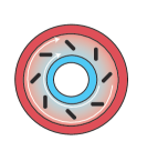
The thermophoretic micropump, sketched in Fig. 1, consists of a microchannel of width of with immersed solid elongated obstacles (pillars) tilted at an angle , typically . Opposite walls have fixed different temperatures, such that the pillars feel a temperature gradient , which will induce an osmotic flow. As indicated in Fig. 1LABEL:sub@fig:obstacle, pillars are modeled by one layer of spherical beads of the diameter , fixed in this work to , placed with anchored positions on the nodes of a triangular lattice. The separation between beads determines the pillar surface rugosity, which is characterized by the ratio between the typical lattice length , and the bead diameter . In this way small values, such as are refereed to as smooth surfaces, large values, such as are referred to as rough. In order to modify the surface thermophoretic properties rugosity is here modified similar to the rod-like colloid case. The rough case corresponds then to porous like material where fluid can cross through the pillars interstices. The pillar thickness is for all rugosities, the particle diameter , and the length is denoted by , which is typically not an integer given the varying values of the rugosity. Periodic boundary conditions (PBC) are considered in the two directions perpendicular to the walls. Pillars are placed with the long axis parallel to the walls, this is in the y direction as depicted in Fig. 1a. This, together with PBC, provides effective extended pillars. Finally, the pillars are equidistantly placed in the direction, with separation . Unless otherwise stated, we perform simulations with , , , and with one obstacle in a cuboid box . The beads positions are invariable with time, and the interaction of the solvent particles with the pillar beads are modelled by Mie potential Gustav (namely, Lennard-Jones type)
| (1) |
Here is the distance between the bead center and the fluid particle, is the potential intensity, chosen as , and is a positive integer describing the potential stiffness. By considering or together with the suitable cutoff distance , the potential is adjusted to be attractive or purely repulsive Lüsebrink et al. (2012), which will be respectively denoted as or . This means for example, that the potential with , , and is the well-known WCA (Weeks-Anderson-Chandler) repulsive potential Weeks et al. (1971).
II.2 Mechanism: anisotropic thermophoresis
The interaction of a colloidal particle with a solvent with a non-homogeneous temperature results in a driving thermophoretic force Yang and Ripoll (2012a, b) which causes the particle migration of non-fixed particles (thermophoresis), or the motion of the surrounding fluid for immobilized objects (thermoosmosis). This force is known to be directly proportional to the temperature gradient,
| (2) |
with the Boltzmann constant, and the thermodiffusion tensor, which is a material dependent property determining the force direction and strength. In the case of spherical particles, is a constant factor, the so-called thermodiffusion factor, ; while other particle shapes might have more complex dependencies. This deviation from the spherical constant behavior has been defined as anisotropic thermophoresis Tan et al. (2017). In the case of elongated particles, two independent coefficients are expected to be enough to determine the thermophoretic properties. These are and , the thermophoretic factors characterizing a rod with the long axis aligned with the temperature gradient, or perpendicular to it. The difference between these two factors defines the thermophoretic anisotropy factor
| (3) |
Interestingly, this means that an elongated particle with fixed an angle with respect to will feel a force not only in the gradient direction, but also perpendicular to it Tan et al. (2017)
| (4) |
where refers to the direction perpendicular to , and the corresponding unit vector. By convention, the sign of the thermodiffusion factor is positive when colloids drift toward cold areas, this is for thermophobic behavior; while is negative for colloids drifting towards warmer areas, this is thermophilic behavior. Previous simulations showed that the use of attractive solvent-colloid potential translates into a thermophobic colloid drift, while repulsive potentials show a thermophobic behaviour. This driven mechanism of the model is essentially related to the relation between the local pressure gradient and the sign of the applied potential Tan (2018); Burelbach et al. (2018). The direction of the perpendicular force in Eq. (4) is determined by the sign of which is in principle independent of the thermophobic or thermophilic character of the surface.
In the microchannel configuration of Fig. 1, the fixed solid pillars endure thermoosmotic flows of the fluid around them. If the obstacles are elongated structures (), tilted with respect to the channel walls and therefore to the temperature gradient (), a net fluid flux will be generated parallel to the channel walls; as can be seen in Fig. 2. The resulting net flux density can be defined as the particle flux per unit volume,
| (5) |
where is the average particle number, and the particle velocity of the fluid at the position . Note that the fluid velocity is not fully considered, but just the velocity component parallel to the walls, since this is the only one that contributes to the net flux. The system symmetry allows us to disregard the system dependence along the obstacle length, which in Fig. 1LABEL:sub@fig:3dscheme corresponds to the -direction. In order to provide a prediction to the corresponding averaged density flux, it is important to note that the normalized number density can be considered proportional to , the averaged number density; while the fluid velocity will be determined by the perpendicular thermophoretic force in Eq. (4), together with an effective friction coefficient proportional to the fluid viscosity . The averaged density flux will be then determined by,
| (6) |
where a fixed angle inclination has already been accounted for, for example its optimal value , and is a function of the microchannel and pillars geometry with inverse of length dimensions. Expression (6) indicates that the intensity of the flux will be determined by several parameters, but the direction will be remarkably only determined by the anisotropic thermophoretic factor .
III Flow pattern and flow flux
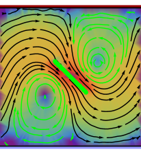
A representative simulation output of the temporally averaged flow streamlines of a cross-section in plane with three pillars is illustrated in Fig. 2. In this flow pattern an “effective flow” region where the fluid passes close to the obstacles and continues along the microchannel with a sinusoidal-like trajectory. Additionally “vortex” region can be identified, where the flow rotates without providing any net contribution to the total flux.
The resulting net flux density as defined in Eq. (5) is computed along the channel, and displayed in Fig. 3(a) normalized by the externally applied temperature gradient. In spite of the stream lines tortuosity, and due to the mass continuity, the flux density is basically constant along the channel (see Fig. 3(a)). Note that the flow does not depend on the position in the axis, such that we average the flow field in this direction to increase the statistics accuracy. Both the flow field and the flux at steady state are temporal average over units of time with at least simulation measurements. Note that increasing the number of simulations would eventually improve the statistical dispersion of the data, and decrease the (not indicated) error bars, but it would not change any of the presented conclusions.
(a)
 0.14in-0.35in
\topinset (b)
0.14in-0.35in
\topinset (b)
 0.22in-0.35in
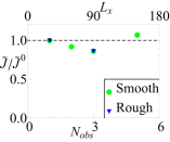
Given the system symmetry and the use of PBC along the channel, the fluid flow is not expected to significantly depend of the number of pillars considered, for a fixed interparticle separation . However, PBC might also lead to fluid correlations, which would be enhanced for smaller system sizes Huang et al. (2012). In Fig. 3(b) measurements of the flux densities are shown for simulations with different number of obstacles in the primary simulation box, , where the box dimension has been accordingly varied . The flux densities show to have a relatively constant value, independent on the system size, and furthermore flow patterns around each pillar are identical for different which allows us to investigate systems with just one pillar without diminishing the applicability of the conclusions.
III.1 Interfacial properties
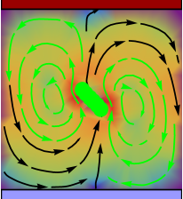
The thermophilic character of the pillar in Fig. 2 can be observed in the flow close to the obstacle surface, where the flow is clearly directed from warm to cold areas, opposite to the thermophoretic force on the pillar beads, as expected Yang and Ripoll (2013). A similar micropump, with an obstacle constructed out of thermophobic beads is displayed in Fig. 4, where the flow directed then to the warm areas can be observed in the neighbourhood of the obstacle surface. In spite of this difference, the overall direction of the flux is the same in these two cases, which results in flow streamlines with significantly different pathways in both cases, as can be seen by the flow close to the pillar and the position of the stagnation point relative to the obstacle.
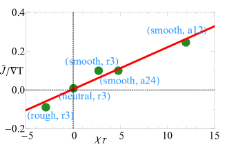
As stated in Eq. (6) the overall direction of the flow parallel to the walls is determined by the anisotropic factor in Eq. (3). This explains that pillars with thermophilic and thermophobic character might still result in flux with the same direction. To further verify this statement we have quantified in some cases by additional simulations with obstacles placed parallel and perpendicular to the channel walls, with a procedure similar to the one described in Ref. Tan et al. (2017). Results and simulation parameters are summarized in Table 1, and the variation of the flux normalized by the applied temperature gradient with the corresponding anisotropic thermophoresis factor is displayed in Fig. 5, where the linear behavior predicted by Eq. (6) is nicely confirmed. Note that in our simulations the pillars along direction are constructed by PBC. Therefore the values of are represented as the measured per unit length along axis.
| potential | |||||
|---|---|---|---|---|---|
The investigation of the anisotropic thermophoretic effect in colloidal rods Tan et al. (2017) showed a sign change of with the rod rugosity. We also explore the dependence with rugosity in the case of elongated obstacles as depicted in Fig. 1LABEL:sub@fig:obstacle, and the explicit measurements of shown in Table 1 display similar sign change. The streamlines for microchannels with elongated rough and neutral thermophilic pillars are plotted in Fig. 6, while the smooth corresponding case can be seen in Fig. 2. The flux direction, as well as the flow pathways are different in the three cases as a consequence of the different values of . Besides the change in flux direction, the location of the vortexes and the corresponding stagnation points vary also with and the thermophoretic character. For the microchannel with smooth thermophilic obstacles (Fig. 2), this is when , the stagnation points are aligned perpendicular to the long pillar axis. On the other hand, for cases with , these are smooth thermophobic (Fig. 4) or rough thermophilic obstacles (Fig. 6(a)); the stagnation points are aligned close to the long pillar axis. Finally, it is interesting to note that there is an intermediate rugosity case, which we call neutral, for which the anisotropic effect vanishes, . This is the case shown in Fig. 6(b) where the flow field shows a symmetric pattern with very close to vanishing flux, which resembles the one induced by a fixed isotropic colloid Yang and Ripoll (2013).
III.2 Channel geometrical properties
Besides the interfacial properties discussed until now, the channel dimensions are naturally going to affect the flow intensity, shape, and exceptionally even its sign, as indicated by the prefactor in Eq. (6) being function of the channel width, pillar interseparation, and obstacle aspect ratio.
Channel width effect
(a) 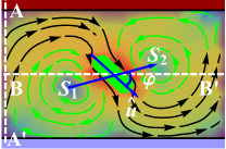 0.2in0.05in
(b) 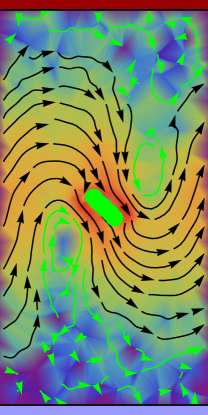 0.2in0.05in
To study the effect of the channel width on the induced flow, we perform simulations varying , approximately from to times the obstacle length , and fixing all the other dimensions to default values, as well as the temperatures at the two walls ( and ). Figure 7 shows the cases with largest and smallest confinements here investigated, which can be compared with the intermediate case in Fig. 2. The confinement provided by the no-slip channel walls restricts the effective flow domain and adjusts the fluid flow perpendicular to the walls rather than parallel to them. This wall-restriction of the flow explains the linear increase of the flux with channel width shown in Fig. 8(a). For channels wide enough, the flow close to the walls is weak, close to , such that confinement does not noticeably affect anymore the flow, and an increase of the channel‘ width results in a straightforward decrease of the net flux. This explains the maximum observed in Fig. 8(a) for channels with .
Additionally, Fig. 7 shows that the channel width also importantly changes size, shape, and location of the vortex regions, which is a consequence of the previously discussed flow distortion. The vortexes can be quantitatively characterized with the location of the middle points of zero flow velocity, by defining the stagnation angle and the normalized stagnation distance . As indicated in Fig. 7(a), is the distance between the two stagnation points and around a given pillar, and is the angle that the line connecting these two points makes with the pillar elongated axis. Fig. 8(a) shows that both these quantities have a maximum at the same point as the normalized flux, and that this occurs when , this is when the vortex middle points are exactly perpendicular with the elongated obstacle. When is as small as shown in Fig. 7(a), the vortex region takes up large part of the microchannel due to the significant confinement in the gradient direction, and the distance between complementary stagnation points is very small. The size and position of the vortex changes exactly until , value from which the vortexes only distort due to the lack of confinement.
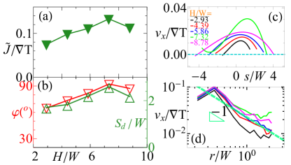
The velocity profiles along the channel direction in the cross-sections perpendicular and parallel to the channel walls are shown in Fig. 8(c) and (d), respectively. Figure 8(c) shows that the velocity profile in between the obstacles is close to parabolic, with a slightly off-center maximum, in which the maximum values of the velocity follows the same dependence as the fluxes in Fig. 8(a). This means that the intensity of the flow decays close to the walls, and this decays is then larger for the widest channels where there can even be a residual flow in opposite direction. The velocity profile along the middle axis parallel to the walls is shown in Fig. 8(d). The flow field in the most immediate proximity of the pillar could be understood as determined by the intrinsic obstacle properties and only weakly modified by the boundary conditions. The velocity profiles in Fig. 8(d) show a decay as the distance from the pillar surface increases. This is similar to the flow for a fixed phoretic colloid, and has the same origin. Deviations from this behavior are due to the confinement.
We have analyzed the dependence of the channel width for just one parameters set, and fixed interfacial properties; we expect almost identical behaviors for other relevant parameter sets, although the exact location of the optimal channel width, here could eventually vary.
Inter-obstacle separation effect
In the limit of vanishing separation between obstacles, there is no expected net flux generated by the micropump; and in the complementary limit, one single pillar will not be able to create a considerable flux in an arbitrary long channel. To most precisely understand the transition between these limits, simulations at various pillar separations have been carried out. Figure 9 shows that the relevance of the vortex area and the tortuosity of the streamlines decreases with increasing obstacle separation. This can be understood since the flow field in the most immediate proximity of the obstacle has an intensity and direction determined by the surface rod properties, while the flow slightly further away from the rod, just needs to adapt to the given boundary conditions.
(a)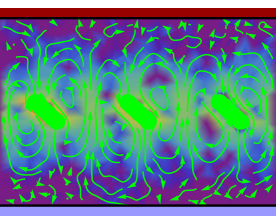 0.2in-1.1in
\topinset (b)
0.2in-1.1in
\topinset (b) 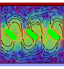 0.2in-0.8in

Decreasing the pillar separation importantly distorts the vortex areas, such that the counter-rotating flow becomes relatively more important. This makes that the net flux importantly decreases for small (but not vanishing) pillar separation reaching a vanishing value as shown in Fig. 9(a), or even negative as shown in Fig. 9(b) and Fig. 10(a). Increasing obstacle separation increases the flux, see Fig. 2, until a maximum value is obtained (, for the parameters here employed), as shown in Fig. 10(a). Increasing the separation further than this optimal value makes the flux decrease, but interestingly, this decay occurs very slowly. In this way, for the case with the largest separation where simulation has been here performed () the total flux is just smaller than that with the optimal separation. This result can be practically advantageous since devices with a smaller number of pillars will typically be easier and therefore cheaper to produce.
The location of the vortexes center, which can be inferred from and in Fig. 10(b), changes with increasing obstacle separation until they reach a stable location. This location does not depend anymore on , and seems therefore to be determined by the value of the channel width. The velocity profiles in the cross-section in between pillars is shown in Fig. 10(c) for various values. The profiles are naturally related to their fluxes, such that small separations show flat profiles which can be averagely negative, vanishing or positive, while larger separations show progressively more parabolic-like profiles slightly tilted towards the pillar direction. Note that the flow induced by this micropump is intrinsically non-parabolic, see for example Fig. 2. The observed close-to-parabolic profiles occur just in the perpendicular axis, in between the pillars for intermediate separations.
The flow parallel to the walls at the center of the channel is shown in Fig. 10(d), where the flow field in the most immediate proximity of the obstacle shows a bit stronger dependence with than with in Fig. 8(d), but with similar decay. Note that the velocity profiles for the smallest inter obstacle separation deviate from the decay scenario since their effective flow patterns are too strongly distorted.
The role of the obstacle aspect ratio
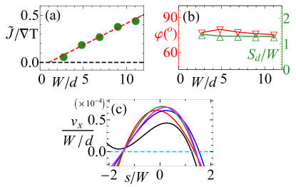
As already described for the case of rodlike colloids Tan et al. (2017), the anisotropic thermophoretic factor of elongated obstacle is expected to increase linearly with aspect ratio, and therefore the driving force along the channel for the anisotropic thermophoretic pump here investigated. In order to investigate the effect of the aspect ratio, and reasonably decouple it from the other geometrical effects, we perform simulations varying channel width and inter-pillar separation by keeping fixed ratios, and , and although its effect can be understood with proper normalization, we here vary the wall temperatures to fix . Figure 11 shows the flow streamlines for the largest aspect ratio here investigated, which can be compared with the streamlines of a smaller aspect ratio in Fig. 2. Interestingly, the flow patters are very similar, what verifies that the shape of the flow streamlines is determined by the ratios and .
The measured normalized averaged flux in Fig. 12(a) very nicely shows to linearly increase with . Moreover, this similarity can be inferred also from the constant stagnation angle as well as the rescaled stagnation distance for different aspect ratios in Fig. 12(b). The flow velocity profiles perpendicular to the walls normalized by show to collapse with a small deviation at the smallest aspect ratio, Fig. 12(c). This linear behavior implies that even with small aspect ratio, we still obtain the same features of the study on the flow patterns and the averaged flux .
III.3 Mapping to physical units
In order to provide an estimation of the actual pumping capability under experimental conditions of the proposed microfluidic device, we need to map the simulation units of the MPC model to those of real physical systems. We employ a similar strategy as the one introduced in Ref. Yang and Ripoll (2016), where three relevant MPC quantities are matched to real physical units. Very reasonable choices are to match the average MPC temperature to K, and the mass density of the solvent to the density of water, . The choice for the length scale is however much more arbitrary, but we can make a realistic choice of channel widths between and m. This allows us to identify , and therefore the typical velocities in this work to be in the order of to m/s, which are competitive for the design of microfluidic devices. Furthermore, higher velocities could be reached since Fig. 12 probes that the velocity linearly increases with the obstacle aspect ratio, given that the channel width to obtacle length ratio, , and more importantly the temperature gradient, , are kept constant. On the other hand, it should be considered that the mesoscopic nature of the solvent makes it impossible to simultaneously match all the relevant physical quantities. In this way, with the above parameter choices, we provide a reasonable match to the ratio , although not to each of the involved quantities. And it is also very important that most parameters employed in the simulations are chosen due to computational efficiency, which is not related to any limitation of the physical phenomenon. Thus, simulations of larger systems, with smaller , and larger are in principle possible, although not really meaningful at this stage. In this sense, the above dimensions should be only taken as an educated guess, being other sizes and velocities possible as well, in particular considering the variaty of properties depending of the employed materials and system conditions.
IV Alternative setups
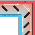
The simulations presented in this work have so far considered only straight microchannels with fixed obstacles placed equidistant from the walls. These are though no restrictions for building functional microfluidic devices based on the anisotropic thermophoretic effect. In case that the pillars are not placed equidistant from the walls, the fluid will stream with a non-symmetric pattern, but in general the net fluid flux will remain. In the limiting situation in which the obstacles are in contact with one of the walls, the system will be similar in spirit to the phoretic ratcheted microchannels Yang and Ripoll (2016); Shen et al. (2016), where a net flux with a shear-like velocity profile is generated. The channels do not need to be straight either, and corners or curved geometries, as those shown in Fig. 13, will not hinder the fluid motion when the pillars are kept at the pertinent titled orientation with respect to the walls. This is particularly important for microfluidic applications of this phenomena, since it shows that implementation in arbitrary geometries is possible.
Other interesting applications of the anisotropic phoretic effect in microfluidics are fluid mixers and generators of alternating flow. Fluid mixers can be obtained by building microchannels with elongated pillars fixed in the middle of the channel with a fixed angle, but with alternating positive and negative orientation, which would be adopting a type of ”w” or symmetric saw disposition. In this case a type of Rayleigh-Bernard counter-rotating vortexes will be induced with sizes determined by the obstacles positions and, rotating velocities given by the temperature gradients and the thermophoretic pillar properties. When two fluids converge into the phoretic micropump with anisotropic obstacles, the mixing will be highly enhanced due the intricate shape of the fluid flow, see for example Fig. 6(b) or Fig. 9(b). For mixing fluids Stone et al. (2004); Marin et al. (2015); Rallabandi et al. (2015); Liu et al. (2002), the pillars can, but do not need to be elongated, and no particular orientation would be necessary.
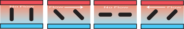
The last structure that we discuss here is the generators of alternating flow, which emulates in some sense the alternating current of electromagnetic devices. The idea is to change the orientation of the pillars with time according to a prescribed protocol. This could be realized if movable obstacles could be engineered, or more realistically, by employing suspended elongated particles with fixed centers of mass, and orientations externally controlled by the use of for example laser tweezers, or rotating magnetic fields. It is straightforward to predict that if the obstacle orientation changes periodically with respect to the channel walls, the net flux will change as indicated in Fig. 14, from being significant in one direction, then cancelling, then significant in the opposite direction and then vanishing again. An example of systems that could be employed for this purpose are magnetizable particles in a non-magnetic fluid, which in the presence of an external rotating magnetic field will rotate with a constant frequency Melle et al. (2003). Although no simulation results are presented for the structures discussed in this section, the extensive results presented in the previous section serve as a strong proof-of-concept. This effect can be used not only as as a flow alternator, but for example also as flow switch.
V Conclusions
We have proposed a strategy to design microfluidic devices based on anisotropic phoresis, this is the asymmetric response of elongated objects to externally applied gradients, depending on their relative orientation.
The magnitude of the flow is determined by the phoretic properties of the pillar surfaces and also by the channel geometric properties. We have shown that this new design can facilitate the tunability of flow velocity and pattern by solely altering the orientation, aspect ratio, rugosity, or phoretic affinity (thermophobic, or thermophilic) of the obstacles inside the same microchannel. The flux naturally increases with the obstacle aspect ratio, and it is directly proportional to the pillar phoretic anisotropic factor. This means that the flux direction is not dictated by the thermophilic or thermophobic character of the surface, but by the anisotropic thermophoretic factor which also depends for example on the surface properties, such as rugosity Tan et al. (2017). This might be counter-intuitive, but it also provides to the devices with an additional degree of versatility. Interestingly, the current device uses anisotropic pillars at the mid-channel, with an orientation which could eventually be manipulated by for instance optical tweezers, this might inspire a new avenue of microfluidic fabrication, such as fluidic switches, mixers, or flow alternators.
The required temperature differences can be experimentally obtained in two fundamentally different ways. One is by laser illumination when one of the wall surfaces is metal coated Jiang et al. (2010); Maggi et al. (2015). Such optical heating can be flexibly and remotely controlled in a very precise and programmable manner, and this microscale optical control can certainly find applications in optofluidics Baigl (2012). Alternatively, the microchannel walls can be in contact with heat reservoirs at different temperatures Weinert and Braun (2008); Vigolo et al. (2010). This contact heating can profit from existing residual heat flux, which would eventually allow these device to harvest part of the waste heat. Moreover, the proposed device can facilitate the cooling down of microscale heat sources, such as microelectronic chips. Furthermore, the current micropump needs only the presence of the walls and a simple fluid, but it will also be effective in the presence of a multicomponent fluid in a single phase or in a multiphase situation, where the pillars could interact with interfaces.
Although the micropumps here proposed have not yet been practically realized, various existing experimental results can serve us as a proof of concept. An example is the osmotic flow which has shown to be responsible for the formation of thermophoretic colloidal crystals close to a substrate Weinert and Braun (2008); Leonardo et al. (2009). Such flow produces an inter-colloidal attraction, which maintains the colloidal assembly only in the presence of a temperature gradient. A different example can be found in the experimental results of a self-thermocapillary asymmetric gear Maggi et al. (2015) showing that a gear with an outer radius of m can rotate with a maximum angular velocity of rad/s when externally heated.
The discussion performed in this work has focused in the thermophoretic case, but very importantly, all our arguments can be straightforwardly generalized to other phoretic effects, such as diffusiophoresis or electrophoresis. This is for example the case of a concentration gradient produced if one of the confining walls would have a catalytic character. Simulation results have already demonstrated anisotropic diffusiophoresis Yang et al. (2015b), as well as the conceptual equivalence of, for example, the thermophoretic gear Yang and Ripoll (2014), and the catalytic counterpart Yang et al. (2015a). Based on this principle, a proof of concept has also been experimentally achieved for catalytic self-electrophoretic microrotors brooks19 , which show how platinum microgears in solutions of hydrogen peroxide with an outer radius of approximately m can rotate with a maximum angular velocity of rad/s. The mechanisms of the phoretic microgears and ratcheted pumps Yang and Ripoll (2016); Shen et al. (2016) are different, but also closely related with the basic principle discussed in this work, what strongly supports the experimental feasibility of the here proposed devices in both their thermal and catalytic versions.
Acknowledgments
M. R. thanks Andrea Costanzo for contributions in a very early stage of this work. The authors acknowledge financial support by China Scholarship Council (CSC), and by the Bavarian Ministry of Economic Affairs and Media, Energy and Technology within the joint projects in the framework of the Helmholtz Institute Erlangen-Nürnberg for Renewable Energy (IEK-11) of Forschungszentrum Jülich. We also gratefully acknowledge the computing time granted on the supercomputer JURECA at Jülich Supercomputing Centre (JSC). M. Y. also acknowledges financial support from the NSFC (No. 11674365). German patent application (No. 102017003455.9) is pending for the work described in this paper.
References
- Whitesides (2006) G. M. Whitesides, “The origins and the future of microfluidics,” Nature 442, 368 (2006).
- Martinez et al. (2017) I. A. Martinez, E. Roldan, L. Dinis, and R. A. Rica, “Colloidal heat engines: a review,” Soft Matter 13, 22 (2017).
- Nisar et al. (2008) A. Nisar, N. Afzulpurkar, B. Mahaisavariya, and A. Tuantranont, “Mems-based micropumps in drug delivery and biomedical applications,” Sens. Actuators, B 130, 917 (2008).
- Herrlich et al. (2012) S. Herrlich, S. Spieth, S. Messner, and R. Zengerle, “Osmotic micropumps for drug delivery,” Adv. Drug Delivery Rev. 64, 1617 (2012).
- Wang and Fu (2018) Y-N Wang and L-M Fu, “Micropumps and biomedical applications – a review,” Microelectron. Eng. 195, 121 (2018).
- Amirouche et al. (2009) F. Amirouche, Y. Zhou, and T. Johnson, “Current micropump technologies and their biomedical applications,” Microsyst. Technol. 15, 647 (2009).
- Byun et al. (2013) C K Byun, K. Abi-Samra, Y-K Cho, and S. Takayama, “Pumps for microfluidic cell culture,” Electrophoresis 35, 245 (2013).
- Squires and Quake (2005) T. M. Squires and Stephen R. Quake, “Microfluidics: Fluid physics at the nanoliter scale,” Rev. Mod. Phys. 77, 977 (2005).
- Stone et al. (2004) H. A. Stone, A. D. Stroock, and A. Ajdari, “Engineering flows in small devices: microfluidics toward a lab-on-a-chip,” Annu. Rev. Fluid Mech. 36, 381 (2004).
- Darhuber and Troian (2005) A. A. Darhuber and S. M. Troian, “Principles of microfluidic actuation by modulation of surface stresses,” Annu. Rev. Fluid Mech. 37, 425 (2005).
- Dauparas et al. (2018) J. Dauparas, D. Das, and E. Lauga, “Helical micropumps near surfaces,” Biomicrofluidics 12, 014108 (2018).
- Zhou et al. (2016) C. Zhou, H. Zhang, Z. Li, and W. Wang, “Chemistry pumps: a review of chemically powered micropumps,” Lab Chip 16, 1797 (2016).
- Michelin et al. (2015) S. Michelin, T. D. Montenegro-Johnson, G. De Canio, N. Lobato-Dauzier, and E. Lauga, “Geometric pumping in autophoretic channels,” Soft Matter 11, 5804 (2015).
- Yang and Ripoll (2016) M. Yang and M. Ripoll, “Thermoosmotic microfluidics,” Soft matter 12, 8564 (2016).
- Paxton et al. (2004) W. F. Paxton, K. C. Kistler, C. C. Olmeda, A. Sen, S. K. St. Angelo, Y. Cao, T. E. Mallouk, P. E. Lammert, and V. H. Crespi, “Catalytic nanomotors: autonomous movement of striped nanorods,” J. Am. Chem. Soc. 126, 13424 (2004).
- Jewell et al. (2016) E. L. Jewell, W. Wang, and T. E. Mallouk, “Catalytically driven assembly of trisegmented metallic nanorods and polystyrene tracer particles,” Soft Matter 12, 2501 (2016).
- Anderson (1989) J. L. Anderson, “Colloid transport by interfacial forces,” Annu. Rev. Fluid Mech. 21, 61 (1989).
- Moran and Posner (2017) J. L. Moran and J. D. Posner, “Phoretic self-propulsion,” Annu. Rev. Fluid Mech. 49, 511 (2017).
- Würger (2010) A. Würger, “Thermal non-equilibrium transport in colloids,” Rep. Prog. Phys. 73, 126601 (2010).
- Piazza and Parola (2008) R. Piazza and A. Parola, “Thermophoresis in colloidal suspensions,” J. Phys.: Condens. Matter 20, 153102 (2008).
- Ganti et al. (2017) R. Ganti, Y. Liu, and D. Frenkel, “Molecular simulation of thermo-osmotic slip,” Phys. Rev. Lett. 119, 038002 (2017).
- Fu et al. (2017) L. Fu, S. Merabia, and L. Joly, “What controls thermo-osmosis? molecular simulations show the critical role of interfacial hydrodynamics,” Phys. Rev. Lett. 119, 214501 (2017).
- Derjaguin et al. (1993) B.V. Derjaguin, G. Sidorenkov, E. Zubashchenko, and E. Kiseleva, “Kinetic phenomena in the boundary layers of liquids 1. the capillary osmosis,” Prog. Surf. Sci. 43, 138 (1993).
- BRADY (2011) J. F. Brady, “Particle motion driven by solute gradients with application to autonomous motion: continuum and colloidal perspectives,” J. Fluid Mech. 667, 216 (2011).
- Howse et al. (2007) J. R. Howse, R. A. L. Jones, A. J. Ryan, T. Gough, R. Vafabakhsh, and R. Golestanian, “Self-motile colloidal particles: From directed propulsion to random walk,” Phys. Rev. Lett. 99, 048102 (2007).
- Saville (1977) D. A. Saville, “Electrokinetic effects with small particles,” Annu. Rev. Fluid Mech. 9, 321 (1977).
- Shendruk et al. (2012) T.N. Shendruk, O.A. Hickey, G.W. Slater, and J.L. Harden, “Electrophoresis: When hydrodynamics matter,” Curr. Opin. Colloid Interface Sci. 17, 74 (2012).
- Hickey et al. (2012) O. A. Hickey, T. N. Shendruk, James L. Harden, and G. W. Slater, “Simulations of free-solution electrophoresis of polyelectrolytes with a finite debye length using the debye-hückel approximation,” Phys. Rev. Lett. 109, 098302 (2012).
- Paxton et al. (2006) W. F. Paxton, P. T. Baker, T. R. Kline, Y. Wang, T. E. Mallouk, and A. Sen, “Catalytically induced electrokinetics for motors and micropumps,” J. Am. Chem. Soc. 128, 14881 (2006), .
- Sengupta et al. (2014) S. Sengupta, D. Patra, I. Ortiz-Rivera, A. Agrawal, S. Shklyaev, K. K Dey, U. Córdova-Figueroa, T. E Mallouk, and A. Sen, “Self-powered enzyme micropumps,” Nat. Chem. 6, 415 (2014).
- Ortiz-Rivera et al. (2016) I. Ortiz-Rivera, H. Shum, A. Agrawal, A. Sen, and A. C. Balazs, “Convective flow reversal in self-powered enzyme micropumps,” Proc. Natl. Acad. Sci. 113, 2585 (2016).
- Das et al. (2017) S. Das, O. E. Shklyaev, A. Altemose, H. Shum, I. Ortiz-Rivera, L. Valdez, T. E. Mallouk, A. C Balazs, and A. Sen, “Harnessing catalytic pumps for directional delivery of microparticles in microchambers,” Nat. Com. 8, 14384 (2017).
- Duhr et al. (2004) S. Duhr, S. Arduini, and D. Braun, “Thermophoresis of dna determined by microfluidic fluorescence,” Eur. Phys. J. E 15, 277 (2004).
- Vigolo et al. (2010) D. Vigolo, R. Rusconi, H. A. Stone, and R. Piazza, “Thermophoresis: microfluidics characterization and separation,” Soft Matter 6, 3489 (2010).
- Tsuji et al. (2017) T. Tsuji, K. Kozai, H. Ishino, and S. Kawano, “Direct observations of thermophoresis in microfluidic systems,” Micro. Nano. Lett. 12, 520 (2017).
- Baigl (2012) D. Baigl, “Photo-actuation of liquids for light-driven microfluidics: state of the art and perspectives,” Lab Chip 12, 3637 (2012).
- Namura et al. (2017) K. Namura, K. Nakajima, and M. Suzuki, “Quasi-stokeslet induced by thermoplasmonic marangoni effect around a water vapor microbubble,” Sci. Rep. 7, 45776 (2017).
- Kline et al. (2005) T. R. Kline, W. F. Paxton, Y. Wang, D. Velegol, T. E. Mallouk, and A. Sen, “Catalytic micropumps: microscopic convective fluid flow and pattern formation,” J. Am. Chem. Soc. 127, 17150 (2005).
- Jiang et al. (2010) H.-R. Jiang, N. Yoshinaga, and M. Sano, “Active motion of a janus particle by self-thermophoresis in a defocused laser beam,” Phys. Rev. Lett. 105, 268302 (2010).
- Liu and Li (2010) C. Liu and Z. Li, “Molecular dynamics simulation of composite nanochannels as nanopumps driven by symmetric temperature gradients,” Phys. Rev. Lett. 105, 174501 (2010).
- Yang and Ripoll (2014) M. Yang and M. Ripoll, “A self-propelled thermophoretic microgear,” Soft Matter 10, 1006 (2014).
- Yang et al. (2015a) M. Yang, M. Ripoll, and K. Chen, “Catalytic microrotor driven by geometrical asymmetry,” J. Chem. Phys. 142, 054902 (2015a).
- Maggi et al. (2015) C. Maggi, F. Saglimbeni, M. Dipalo, F. De Angelis, and R. Di Leonardo, “Micromotors with asymmetric shape that efficiently convert light into work by thermocapillary effects,” Nat. Commun. 6 (2015).
- Tan et al. (2017) Z. Tan, M. Yang, and M. Ripoll, “Anisotropic thermophoresis,” Soft Matter , 7283 (2017).
- Yang et al. (2014) M. Yang, R. Liu, M. Ripoll, and K. Chen, “A microscale thermophoretic turbine driven by external diffusive heat flux,” Nanoscale 6, 13550 (2014).
- Yang et al. (2015b) M. Yang, R. Liu, M. Ripoll, and K. Chen, “A microscale turbine driven by diffusive mass flux,” Lab Chip 15, 3912 (2015b).
- Tasinkevych et al. (2014) M. Tasinkevych, M. G. Campbell, and I. I. Smalyukh, “Splitting, linking, knotting, and solitonic escape of topological defects in nematic drops with handles,” P. Natl. Acad. Sci. 111, 16268 (2014).
- Liu et al. (2013) Q. Liu, B. Senyuk, M. Tasinkevych, and I. I. Smalyukh, “Nematic liquid crystal boojums with handles on colloidal handlebodies,” P. Natl. Acad. Sci. 110, 9231 (2013).
- Malevanets and Kapral (1999) A. Malevanets and R. Kapral, “Mesoscopic model for solvent dynamics,” J. Chem. Phys. 110, 8605 (1999).
- Malevanets and Kapral (2000) A. Malevanets and R. Kapral, “Solute molecular dynamics in a mesoscale solvent,” J. Chem. Phys. 112, 7260 (2000).
- Kapral (2008) R. Kapral, “Multiparticle collision dynamics: Simulation of complex systems on mesoscales,” Adv. Polym. Sci., 140, 89 (2008).
- Gompper et al. (2009) G. Gompper, T. Ihle, D. M. Kroll, and R. G. Winkler, “Multi-particle collision dynamics: A particle-based mesoscale simulation approach to the hydrodynamics of complex fluids,” Adv. Polym. Sci., 221, 1 (2009).
- Ihle and Kroll (2001) T. Ihle and D. M. Kroll, “Stochastic rotation dynamics: A galilean-invariant mesoscopic model for fluid flow,” Phys. Rev. E 63, 020201 (2001).
- Ihle and Kroll (2003) T. Ihle and D. M. Kroll, “Stochastic rotation dynamics. ii. transport coefficients, numerics, and long-time tails,” Phys. Rev. E 67, 066706 (2003).
- Tüzel et al. (2006) E. Tüzel, T. Ihle, and D. M. Kroll, “Dynamic correlations in stochastic rotation dynamics,” Phys. Rev. E 74, 056702 (2006).
- Ripoll et al. (2005) M. Ripoll, K. Mussawisade, R. G. Winkler, and G. Gompper, “Dynamic regimes of fluids simulated by multiparticle-collision dynamics,” Phys. Rev. E 72, 016701 (2005).
- Ripoll et al. (2004) M. Ripoll, K. Mussawisade, R. G. Winkler, and G. Gompper, “Low-reynolds-number hydrodynamics of complex fluids by multi-particle-collision dynamics,” Europhys. Lett. 68, 106 (2004).
- Lüsebrink and Ripoll (2012) D. Lüsebrink and M. Ripoll, “Temperature inhomogeneities simulated with multiparticle-collision dynamics,” J. Chem. Phys. 136, 084106 (2012).
- Yang and Ripoll (2013) M. Yang and M. Ripoll, “Thermophoretically induced flow field around a colloidal particle,” Soft Matter 9, 4661 (2013).
- (60) M. Gustav, “Zur kinetischen theorie der einatomigen körper,” Annalen der Physik 316, 657.
- Lüsebrink et al. (2012) D. Lüsebrink, M. Yang, and M. Ripoll, “Thermophoresis of colloids by mesoscale simulations,” J. Phys.: Condensed Matter 24, 284132 (2012).
- Weeks et al. (1971) J. D. Weeks, D. Chandler, and H. C. Andersen, “Role of repulsive forces in determining the equilibrium structure of simple liquids,” The Journal of Chemical Physics 54, 5237 (1971).
- Yang and Ripoll (2012a) M. Yang and M. Ripoll, “Driving forces and polymer hydrodynamics in the soret effect,” J. Phys.: Condens. Matter 24, 195101 (2012a).
- Yang and Ripoll (2012b) M. Yang and M. Ripoll, “Drift velocity in non-isothermal inhomogeneous systems,” J. Chem. Phys. 136, 204508 (2012b).
- Tan (2018) Z. Tan, Ph.D. thesis, Universität zu Köln (2018).
- Burelbach et al. (2018) J. Burelbach, D. B. Brueckner, D. Frenkel, and E. Eiser, “Thermophoretic forces on a mesoscopic scale,” Soft Matter 14, 7446 (2018).
- Huang et al. (2012) C.-C. Huang, G. Gompper, and R. G. Winkler, “Hydrodynamic correlations in multiparticle collision dynamics fluids,” Phys. Rev. E 86, 056711 (2012).
- Shen et al. (2016) M. Shen, F. Ye, R. Liu, K. Chen, M. Yang, and M. Ripoll, “Chemically driven fluid transport in long microchannels,” The J. Chem. Phys. 145, 124119 (2016).
- Marin et al. (2015) A. Marin, M. Rossi, B. Rallabandi, C. Wang, S. Hilgenfeldt, and C. J. Kähler, “Three-dimensional phenomena in microbubble acoustic streaming,” Phys. Rev. Applied 3, 041001 (2015).
- Rallabandi et al. (2015) B. Rallabandi, A. Marin, M. Rossi, C. J. Kähler, and S. Hilgenfeldt, “Three-dimensional streaming flow in confined geometries,” J. Fluid. Mech. 777, 408 (2015).
- Liu et al. (2002) R. H. Liu, J. Yang, M. Z. Pindera, M. Athavale, and P. Grodzinski, “Bubble-induced acoustic micromixing,” Lab Chip 2, 151 (2002).
- Melle et al. (2003) S. Melle, O. G. Calderón, M. A. Rubio, and G. G. Fuller, “Microstructure evolution in magnetorheological suspensions governed by mason number,” Phys. Rev. E 68, 041503 (2003).
- Weinert and Braun (2008) F. M. Weinert and D. Braun, “Observation of slip flow in thermophoresis,” Phys. Rev. Lett. 101, 168301 (2008).
- Leonardo et al. (2009) R. Di Leonardo, F. Ianni, and G. Ruocco, “Colloidal attraction induced by a temperature gradient,” Langmuir 25, 4247 (2009).
- (75) A. M. Brooks, M. Tasinkevych, S. Sabrina, D. Velegol, A. Sen and K. J. M. Bishop, “Shape-directed rotation of homogeneous micromotors via catalytic self-electrophoresis,” Nat. Commun., 10, 495 (2019).