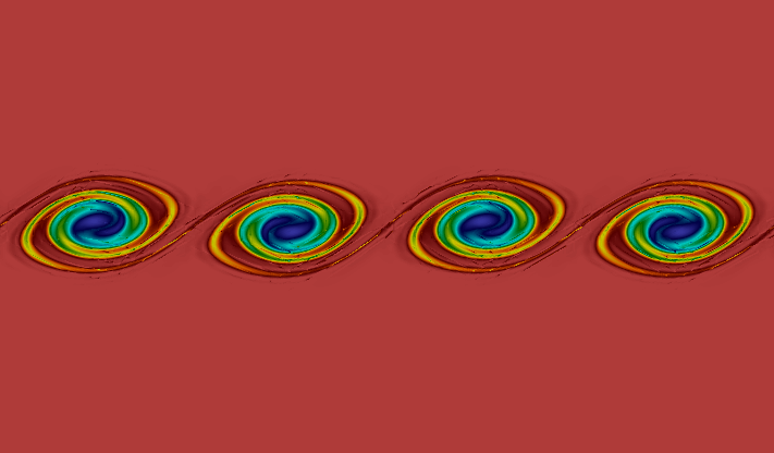
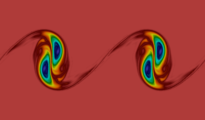
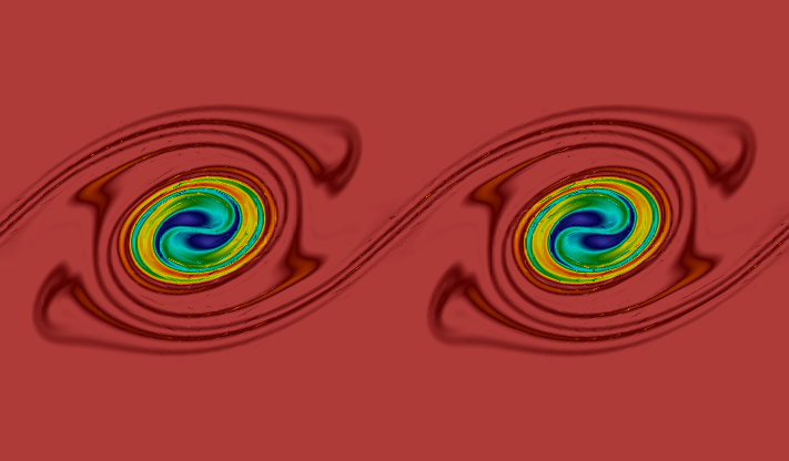
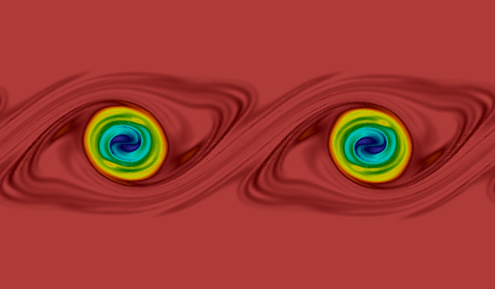
An explicit divergence-free DG method for incompressible flow

Guosheng Fu Division of Applied Mathematics, Brown University, 182 George St, Providence RI 02912, USA. Guosheng_Fu@brown.edu
Abstract.

We present an explicit divergence-free DG method for incompressible flow based on velocity formulation only. An H(div)𝐻divH(\mathrm{div})-conforming, and globally divergence-free finite element space is used for the velocity field, and the pressure field is eliminated from the equations by design. The resulting ODE system can be discretized using any explicit time stepping methods. We use the third order strong-stability preserving Runge-Kutta method in our numerical experiments. Our spatial discretization produces the identical velocity field as the divergence-conforming DG method of Cockburn et al. [8] based on a velocity-pressure formulation, when the same DG operators are used for the convective and viscous parts.

Due to the global nature of the divergence-free constraint and its interplay with the boundary conditions, it is very hard to construct local bases for our finite element space. Here we present a key result on the efficient implementation of the scheme by identifying the equivalence of the mass matrix inversion of the globally divergence-free finite element space to a standard (hybrid-)mixed Poisson solver. Hence, in each time step, a (hybrid-)mixed Poisson solver is used, which reflects the global nature of the incompressibility condition. In the actual implementation of this fully discrete scheme, the pressure field is also computed (via the hybrid-mixed Poisson solver). Hence, the scheme can be interpreted as a velocity-pressure formulation that treat the incompressibility constraint and pressure forces implicitly, but the viscous and convective part explicitly. Since we treat viscosity explicitly for the Navier-Stokes equation, our method shall be best suited for unsteady high-Reynolds number flows so that the CFL constraint is not too restrictive.

1991 Mathematics Subject Classification:
65N30, 65N12, 76S05, 76D07

1. Introduction

It is highly desirable to have a velocity field that is point-wisely divergence-free (exactly mass conservation) for incompressible flows; see the recent review article [17].

We propose a new explicit, high-order, divergence-free DG scheme for the unsteady incompressible Euler and Navier-Stokes equation based on a solely velocity formulation. The pressure field and incompressibility constraint are eliminated from the equation by design. Our semi-discrete scheme produce exactly the same velocity field as the divergence-conforming DG method of Cockburn et al. [8]. Hence, our scheme enjoys features such as global and local conservation properties, high-order accuracy, energy-stability, and pressure-robustness [8, 16].

The resulting semi-discrete scheme is an ODE system for velocity only, as opposite to the differential-algebraic equations (DAE) in [8] where the pressure field and incompressibility-constraint enter into the equations directly. As a consequence, we can apply any explicit time-stepping techniques to solve the ODE system. Our explicit fully-discrete scheme is also equivalence to the velocity-pressure formulation [8] coupled with corresponding explicit treatments for the convective and viscous parts, and implicit treatments for the pressure forces and divergence-free constraint. Such temporal treatment has already been briefly discussed in [19, Section 3.2.1].

Within each time step, the mass matrix for the divergence-free finite element space shall be inverted. Due to the non-locality of the divergence-free constraint in the finite element space and its interplay with the boundary conditions, it is very hard, if possible, to construct the local bases. Here we consider alternative formulations for the efficient implementation of the fully-discrete scheme. In particular, we either relax the divergence-free condition or the divergence-conformity condition in the finite elements via proper Lagrange multipliers, which yields a mixed Poisson solver or a hybrid-mixed Poisson solver in each time stage. The hybrid-mixed formulation is used in our numerical simulations.

We treat the viscosity term explicitly to avoid a Stokes solver. Hence, our scheme shall be applied to unsteady high-Reynolds number, unresolved flows so that the CFL constraint is not too restrictive. Roughly speaking, when both convective and viscous terms are treated explicitly as in our scheme, the following time stepping restriction for stability is to be expected

Δtmin{cChk21vmax,cBh2k41ν},Δ𝑡subscript𝑐𝐶superscript𝑘21subscript𝑣subscript𝑐𝐵superscript2superscript𝑘41𝜈\displaystyle\Delta t\leq\min\left\{c_{C}\frac{h}{k^{2}}\frac{1}{v_{\max}},c_{B}\frac{h^{2}}{k^{4}}\frac{1}{\nu}\right\},

where ΔtΔ𝑡\Delta t is the time step size, hh is the mesh size, k𝑘k is the polynomial degree in the finite elements, vmaxsubscript𝑣v_{\max} is the maximal velocity magnitude, ν𝜈\nu is the viscosity coefficient, and cB,cC>0subscript𝑐𝐵subscript𝑐𝐶0c_{B},c_{C}>0 are the CFL stability constants for the convective and viscous parts, respectively. If we denote the mesh Reynolds number RehsubscriptRe\mathrm{Re}_{h} as

Reh:=vmaxhνk2,assignsubscriptResubscript𝑣𝜈superscript𝑘2\displaystyle\mathrm{Re}_{h}:=\frac{v_{\max}h}{\nu\,k^{2}}, (1)

then the above time stepping restriction becomes

Δtmin{cC,cBReh}hk21vmax.Δ𝑡subscript𝑐𝐶subscript𝑐𝐵subscriptResuperscript𝑘21subscript𝑣\displaystyle\Delta t\leq\min\left\{c_{C},c_{B}\mathrm{Re}_{h}\right\}\frac{h}{k^{2}}\frac{1}{v_{\max}}. (2)

Hence, as long as the mesh Reynolds number Reh1much-greater-thansubscriptRe1\mathrm{Re}_{h}\gg 1 (unresolved flow), or cCcBRehsubscript𝑐𝐶subscript𝑐𝐵subscriptRec_{C}\approx c_{B}\,\mathrm{Re}_{h} (slightly resolved flow), the explicit treatment of viscous term does not pose extra severe time-stepping restrictions besides the CFL constraint from the explicit convection treatment.

On the other hand, when Reh1much-less-thansubscriptRe1\mathrm{Re}_{h}\ll 1, i.e., when the flow is highly resolved, explicit treatment of the viscous term would not be efficient anymore. In this case, we suggest to treat the viscous term implicitly with a divergence-conforming hybridizable DG (HDG) method [19, 20]. Therein, various stiffly accurate operator-splitting time integration approaches were discussed, including additive decomposition methods like IMplicit-EXplicit(IMEX) schemes [4, 7, 18], product decomposition methods like the operator-integration-factor splittings [22], and an operator-splitting modification of the fractional step method [14].

Comparing with other schemes that treat viscosity explicitly, the computational cost of our scheme is comparable to the DG scheme based on a vorticity-stream function formulation [21] in two dimensions, and is a lot cheaper than the vorticity-vector potential formulation [10] in three dimensions. A significant computational saving per time step (one hybrid-mixed Poisson solver/step) is achieved comparing with methods that treat viscosity term implicitly, e.g. the IMEX divergence-conforming HDG scheme [20] (one Stokes solver/step) or the projection methods [15] (d+1𝑑1d+1 Poisson solver/step with d𝑑d the space dimension). Finally, we shall mention that boundary condition is easy to impose for our velocity-based formulation (and for various mixed methods based on velocity-pressure formulations [17]), while that consists one of the major bottlenecks for vorticity-based methods [9] or projection methods [15].

The rest of the paper is organized as follows. In Section 2, the explicit divergence-free DG scheme is introduced for the incompressible Euler equation, along with a key result on transforming the mass matrix inversion to a hybrid-mixed Poisson solver. In Section 3, the scheme is extended to the incompressible Navier-Stokes equations. Extensive numerical results in two dimensions are presented in Section 4. Finally we conclude in Section 5.

2. Euler equations

We consider the following incompressible Euler equations:

t𝒖+(𝒖)𝒖+p=subscript𝑡𝒖𝒖𝒖𝑝absent\displaystyle\partial_{t}\boldsymbol{u}+(\boldsymbol{u}\cdot\nabla)\boldsymbol{u}+\nabla p= 𝒇,𝒇\displaystyle\;\boldsymbol{f}, in Ω,in Ω\displaystyle\text{ in }\Omega, (3a)
𝒖=𝒖absent\displaystyle{\nabla\cdot}\boldsymbol{u}=  0, 0\displaystyle\;0, in Ω,in Ω\displaystyle\text{ in }\Omega, (3b)
𝒖𝒏=𝒖𝒏absent\displaystyle\boldsymbol{u}\cdot\boldsymbol{n}= g,𝑔\displaystyle\;g, on Ω,on Ω\displaystyle\text{ on }\partial\Omega, (3c)

with initial condition

𝒖(x,0)=𝒖0(x)xΩ,formulae-sequence𝒖𝑥0subscript𝒖0𝑥for-all𝑥Ω\boldsymbol{u}(x,0)=\boldsymbol{u}_{0}(x)\quad\forall x\in\Omega,

where 𝒖𝒖\boldsymbol{u} is the velocity and p𝑝p is the pressure, ΩdΩsuperscript𝑑\Omega\subset\mathbb{R}^{d}(d=2,3) is a polygonal/polyhedral domain, and 𝒏𝒏\boldsymbol{n} is the outward normal direction on the domain boundary ΩΩ\partial\Omega. The initial velocity 𝒖0(x)subscript𝒖0𝑥\boldsymbol{u}_{0}(x) is assumed to be divergence-free. For simplicity, we assume no source/sink and no-flow boundary conditions, 𝒇=0𝒇0\boldsymbol{f}=0 and g=0𝑔0g=0. The inflow/outflow boundary conditions will be discussed at the end of this section.

2.1. Preliminaries

Let 𝒯hsubscript𝒯{\mathcal{T}_{h}} be a conforming simplicial triangulation of ΩΩ\Omega. For any element T𝒯h𝑇subscript𝒯T\in{\mathcal{T}_{h}}, we denote by hTsubscript𝑇h_{T} its diameter and we denote by hh the maximum diameter over all mesh elements. Denote by hsubscript\mathcal{F}_{h} the set of facets of 𝒯hsubscript𝒯{\mathcal{T}_{h}}, and by hi=h\Ωsuperscriptsubscript𝑖\subscriptΩ\mathcal{F}_{h}^{i}=\mathcal{F}_{h}\backslash\partial\Omega the set of interior facets.

We denote the following set of finite element spaces:

𝑽h,𝖽𝗀k:=assignsuperscriptsubscript𝑽𝖽𝗀𝑘absent\displaystyle\boldsymbol{V}_{\!h,\mathsf{dg}}^{k}:= T𝒯h[k(T)]d,subscriptproduct𝑇subscript𝒯superscriptdelimited-[]superscript𝑘𝑇𝑑\displaystyle\;\prod_{T\in{\mathcal{T}_{h}}}[\mathbb{P}^{k}(T)]^{d}, (4a)
𝑽h,𝖽𝗀k,m:=assignsuperscriptsubscript𝑽𝖽𝗀𝑘𝑚absent\displaystyle\boldsymbol{V}_{\!h,\mathsf{dg}}^{k,m}:= {𝒗𝑽h,𝖽𝗀k,𝒗|Tm(T)T𝒯h.},\displaystyle\;\{\boldsymbol{v}\in\boldsymbol{V}_{\!h,\mathsf{dg}}^{k},\;\;{\nabla\cdot}\boldsymbol{v}|_{T}\in\mathbb{P}^{m}(T)\;\;\forall T\in{\mathcal{T}_{h}}.\}, (4b)
𝑽hk:=assignsuperscriptsubscript𝑽𝑘absent\displaystyle\boldsymbol{V}_{\!h}^{k}:= {𝒗𝑽h,𝖽𝗀k,[[𝒗𝒏]]F=0Fh.}H0(div,Ω),\displaystyle\;\{\boldsymbol{v}\in\boldsymbol{V}_{\!h,\mathsf{dg}}^{k},\;\;[\![{\boldsymbol{v}\cdot\boldsymbol{n}}]\!]_{F}=0\;\;\forall F\in\mathcal{F}_{h}.\}\subset H_{0}(\mathrm{div},\Omega), (4c)
𝑽hk,m:=assignsuperscriptsubscript𝑽𝑘𝑚absent\displaystyle\boldsymbol{V}_{\!h}^{k,m}:= {𝒗𝑽hk,𝒗m(T)T𝒯h.},\displaystyle\;\{\boldsymbol{v}\in\boldsymbol{V}_{\!h}^{k},\;\;{\nabla\cdot}\boldsymbol{v}\in\mathbb{P}^{m}(T)\;\;\forall T\in{\mathcal{T}_{h}}.\}, (4d)
Qhm:=assignsuperscriptsubscript𝑄𝑚absent\displaystyle Q_{h}^{m}:= (T𝒯hm(T))L02(Ω),subscriptproduct𝑇subscript𝒯superscript𝑚𝑇superscriptsubscript𝐿02Ω\displaystyle\;\left(\prod_{T\in{\mathcal{T}_{h}}}\mathbb{P}^{m}(T)\right)\cap L_{0}^{2}(\Omega), (4e)
Mhk:=assignsuperscriptsubscript𝑀𝑘absent\displaystyle M_{h}^{k}:= Fhk(F),subscriptproduct𝐹subscriptsuperscript𝑘𝐹\displaystyle\;\prod_{F\in\mathcal{F}_{h}}\mathbb{P}^{k}(F), (4f)
where the polynomial degree k1𝑘1k\geq 1 and 1mk11𝑚𝑘1-1\leq m\leq k-1, and [[]]delimited-[]delimited-[][\![\cdot]\!] is the usual jump operator and rsuperscript𝑟\mathbb{P}^{r} the space of polynomials up to degree r𝑟r with the convention that 1={0}superscript10\mathbb{P}^{-1}=\{0\}. Note that functions in Mhksuperscriptsubscript𝑀𝑘M_{h}^{k} are defined only on the mesh skeleton hsubscript\mathcal{F}_{h}, which will be used in the hybrid-mixed Poisson solver.

Finally, we introduce the jump and average notation. Let ϕhsubscriptbold-italic-ϕ\boldsymbol{\phi}_{h} be any function in 𝑽h,𝖽𝗀ksuperscriptsubscript𝑽𝖽𝗀𝑘\boldsymbol{V}_{\!h,\mathsf{dg}}^{k}. On each facet Fhi𝐹superscriptsubscript𝑖F\in\mathcal{F}_{h}^{i} shared by two elements Ksuperscript𝐾K^{-} and K+superscript𝐾K^{+}, we denote (ϕh)±|F=(ϕh)|K±evaluated-atsuperscriptsubscriptbold-italic-ϕplus-or-minus𝐹evaluated-atsubscriptbold-italic-ϕsuperscript𝐾plus-or-minus(\boldsymbol{\phi}_{h})^{\pm}|_{F}=\left.(\boldsymbol{\phi}_{h})\right|_{K^{\pm}}, and use

[[ϕh]]|F=ϕh+𝒏++ϕh𝒏,{{ϕh}}|F=12(ϕh++ϕh)formulae-sequenceevaluated-atdelimited-[]delimited-[]subscriptbold-italic-ϕ𝐹superscriptsubscriptbold-italic-ϕsuperscript𝒏superscriptsubscriptbold-italic-ϕsuperscript𝒏evaluated-atsubscriptbold-italic-ϕ𝐹12superscriptsubscriptbold-italic-ϕsuperscriptsubscriptbold-italic-ϕ\displaystyle[\![{\boldsymbol{\phi}_{h}}]\!]|_{F}=\boldsymbol{\phi}_{h}^{+}\cdot\boldsymbol{n}^{+}+\boldsymbol{\phi}_{h}^{-}\cdot\boldsymbol{n}^{-},\quad\quad\{\!\!\{{\boldsymbol{\phi}_{h}}\}\!\!\}|_{F}=\frac{1}{2}(\boldsymbol{\phi}_{h}^{+}+\boldsymbol{\phi}_{h}^{-}) (5)

to denote the jump and the average of ϕhVhksubscriptitalic-ϕsuperscriptsubscript𝑉𝑘\phi_{h}\in V_{h}^{k} on the facet F𝐹F.

2.2. Spatial discretization

The divergence-free space 𝑽hk,1superscriptsubscript𝑽𝑘1\boldsymbol{V}_{\!h}^{k,-1} shall be used in our DG formulation. With this space in use, the divergence-free constraint (3b) is point-wisely satisfied by design, and the pressure do not enter into the weak formulation of the scheme. The semi-discrete scheme reads as follows: find 𝒖h(t)𝑽hk,1subscript𝒖𝑡superscriptsubscript𝑽𝑘1\boldsymbol{u}_{h}(t)\in\boldsymbol{V}_{\!h}^{k,-1} such that

(t𝒖h,𝒗h)𝒯h+𝒞h(𝒖h;𝒖h,𝒗h)=0,𝒗h𝑽hk,1.formulae-sequencesubscriptsubscript𝑡subscript𝒖subscript𝒗subscript𝒯subscript𝒞subscript𝒖subscript𝒖subscript𝒗0for-allsubscript𝒗superscriptsubscript𝑽𝑘1\displaystyle(\partial_{t}\boldsymbol{u}_{h},\boldsymbol{v}_{h})_{{\mathcal{T}_{h}}}+\mathcal{C}_{h}(\boldsymbol{u}_{h};\boldsymbol{u}_{h},\boldsymbol{v}_{h})=0,\quad\forall\boldsymbol{v}_{h}\in\boldsymbol{V}_{\!h}^{k,-1}. (6)

where (,)𝒯hsubscriptsubscript𝒯(\cdot,\cdot)_{\mathcal{T}_{h}} denotes the standard L2superscript𝐿2L^{2}-inner product, and the upwinding trilinear form

𝒞h(𝒖h;𝒖h,𝒗h):=T𝒯hT(𝒖h𝒖h):𝒗hdx+T(𝒖h𝒏)(𝒖h𝒗h)ds:assignsubscript𝒞subscript𝒖subscript𝒖subscript𝒗subscript𝑇subscript𝒯subscript𝑇tensor-productsubscript𝒖subscript𝒖subscript𝒗dxsubscript𝑇subscript𝒖𝒏superscriptsubscript𝒖subscript𝒗ds\displaystyle\mathcal{C}_{h}(\boldsymbol{u}_{h};\boldsymbol{u}_{h},\boldsymbol{v}_{h}):=\sum_{T\in{\mathcal{T}_{h}}}\int_{T}-(\boldsymbol{u}_{h}\otimes\boldsymbol{u}_{h}):{\nabla}\boldsymbol{v}_{h}\,\mathrm{dx}+\int_{\partial T}(\boldsymbol{u}_{h}\cdot\boldsymbol{n})({\boldsymbol{u}}_{h}^{-}\cdot\boldsymbol{v}_{h})\,\mathrm{ds}

where the upwinding numerical flux 𝒖h|F=𝒖h|Kevaluated-atsuperscriptsubscript𝒖𝐹evaluated-atsubscript𝒖superscript𝐾{\boldsymbol{u}}_{h}^{-}|_{F}=\boldsymbol{u}_{h}|_{K^{-}} with Ksuperscript𝐾K^{-} being the element such that its outward normal direction 𝒏superscript𝒏\boldsymbol{n}^{-} on the facet F𝐹F satisfies 𝒖h𝒏0superscriptsubscript𝒖superscript𝒏0{\boldsymbol{u}}_{h}^{-}\cdot\boldsymbol{n}^{-}\geq 0 (outflow boundary).

Since

𝒞h(𝒖h;𝒖h,𝒖h)=FhiF|𝒖h𝒏|([[𝒖h]][[𝒖h]])ds0,subscript𝒞subscript𝒖subscript𝒖subscript𝒖subscript𝐹superscriptsubscript𝑖subscript𝐹subscript𝒖𝒏delimited-[]delimited-[]subscript𝒖delimited-[]delimited-[]subscript𝒖ds0\mathcal{C}_{h}(\boldsymbol{u}_{h};\boldsymbol{u}_{h},\boldsymbol{u}_{h})=\sum_{F\in\mathcal{F}_{h}^{i}}\int_{F}|\boldsymbol{u}_{h}\cdot\boldsymbol{n}|([\![{\boldsymbol{u}_{h}}]\!]\cdot[\![{\boldsymbol{u}_{h}}]\!])\,\mathrm{ds}\geq 0,

the scheme (6) is energy-stable in the sense that

t𝒖h2(t)𝒯h0,subscript𝑡subscriptnormsuperscriptsubscript𝒖2𝑡subscript𝒯0\partial_{t}\|\boldsymbol{u}_{h}^{2}(t)\|_{{\mathcal{T}_{h}}}\leq 0,

where 𝒯h\|\cdot\|_{\mathcal{T}_{h}} denotes the L2superscript𝐿2L^{2}-norm on 𝒯hsubscript𝒯{\mathcal{T}_{h}}.

2.3. Temporal discretization

The semi-discrete scheme (6) can be written as

(t𝒖h)=(𝒖h),subscript𝑡subscript𝒖subscript𝒖\mathcal{M}(\partial_{t}\boldsymbol{u}_{h})=\mathcal{L}(\boldsymbol{u}_{h}),

where \mathcal{M} is the mass matrix for the space 𝑽hk,1superscriptsubscript𝑽𝑘1\boldsymbol{V}_{\!h}^{k,-1}, and (𝒖h)subscript𝒖\mathcal{L}(\boldsymbol{u}_{h}) the spatial discretization operator. Any explicit time stepping techniques can be applied to the scheme (6). We use the following three-stage, third-order strong-stability preserving Runge-Kutta method (TVD-RK3) [29] in our numerical experiments:

𝒖h(1)=superscriptsubscript𝒖1absent\displaystyle\mathcal{M}\boldsymbol{u}_{h}^{(1)}= 𝒖hn+Δtn(𝒖hn),superscriptsubscript𝒖𝑛Δsuperscript𝑡𝑛superscriptsubscript𝒖𝑛\displaystyle\;\mathcal{M}\boldsymbol{u}_{h}^{n}+\Delta t^{n}\mathcal{L}(\boldsymbol{u}_{h}^{n}),
𝒖h(2)=superscriptsubscript𝒖2absent\displaystyle\mathcal{M}\boldsymbol{u}_{h}^{(2)}= 34𝒖hn+14[𝒖h(1)+Δtn(𝒖h(1))],34superscriptsubscript𝒖𝑛14delimited-[]superscriptsubscript𝒖1Δsuperscript𝑡𝑛superscriptsubscript𝒖1\displaystyle\;\frac{3}{4}\mathcal{M}\boldsymbol{u}_{h}^{n}+\frac{1}{4}\left[\mathcal{M}\boldsymbol{u}_{h}^{(1)}+\Delta t^{n}\mathcal{L}(\boldsymbol{u}_{h}^{(1)})\right], (8)
𝒖hn+1=superscriptsubscript𝒖𝑛1absent\displaystyle\mathcal{M}\boldsymbol{u}_{h}^{n+1}= 13𝒖hn+23[𝒖h(2)+Δtn(𝒖h(2))],13superscriptsubscript𝒖𝑛23delimited-[]superscriptsubscript𝒖2Δsuperscript𝑡𝑛superscriptsubscript𝒖2\displaystyle\;\frac{1}{3}\mathcal{M}\boldsymbol{u}_{h}^{n}+\frac{2}{3}\left[\mathcal{M}\boldsymbol{u}_{h}^{(2)}+\Delta t^{n}\mathcal{L}(\boldsymbol{u}_{h}^{(2)})\right],

where 𝒖hnsuperscriptsubscript𝒖𝑛\boldsymbol{u}_{h}^{n} is the given velocity at time level tnsuperscript𝑡𝑛t^{n} and 𝒖hn+1superscriptsubscript𝒖𝑛1\boldsymbol{u}_{h}^{n+1} is the computed velocity at time level tn+1=tn+Δtnsuperscript𝑡𝑛1superscript𝑡𝑛Δsuperscript𝑡𝑛t^{n+1}=t^{n}+\Delta t^{n}. In each time step, three mass matrix inversion is needed.

Remark 1 (Implementation).

Despite the mathematical simplicity of the solely velocity based formulation (6) and the ease of using explicit time stepping methods of the resulting ODE system, to the best of our knowledge, the method was never directly implemented in the literature. The major obstacle is that the space 𝐕hk,1superscriptsubscript𝐕𝑘1\boldsymbol{V}_{\!h}^{k,-1} is not a standard finite element space whose basis functions can be easily defined, due to the built-in global divergence-free constraint and its interplay with the boundary conditions. By the finite element de Rham complex property[3], we have, in two dimensions,

𝑽hk,1=×{ϕH1(Ω):\displaystyle\boldsymbol{V}_{\!h}^{k,-1}=\nabla\times\Big{\{}\phi\in H^{1}(\Omega): ϕ|Tk+1(T),T𝒯h,formulae-sequenceevaluated-atitalic-ϕ𝑇superscript𝑘1𝑇for-all𝑇subscript𝒯\displaystyle\quad\phi|_{T}\in\mathbb{P}^{k+1}(T),\;\;\;\forall T\in{\mathcal{T}_{h}},
(×ϕ)𝒏=0 on Ω},\displaystyle\;\;\quad\quad(\nabla\times\phi)\cdot\boldsymbol{n}=0\text{ on }\partial\Omega\Big{\}},

where the two-dimension curlcurl\mathrm{curl} operator “ ×\nabla\times” is the rotated gradient, and, in three dimensions,

𝑽hk,1=×{ϕH(curl,Ω):\displaystyle\boldsymbol{V}_{\!h}^{k,-1}=\nabla\times\Big{\{}\boldsymbol{\phi}\in H(\mathrm{curl},\Omega): ϕ|T[k+1(T)]3,T𝒯h,formulae-sequenceevaluated-atbold-italic-ϕ𝑇superscriptdelimited-[]superscript𝑘1𝑇3for-all𝑇subscript𝒯\displaystyle\quad\boldsymbol{\phi}|_{T}\in[\mathbb{P}^{k+1}(T)]^{3},\;\forall T\in{\mathcal{T}_{h}},
(×ϕ)𝒏=0 on Ω}.\displaystyle\;\;\;\quad\quad(\nabla\times\boldsymbol{\phi})\cdot\boldsymbol{n}=0\text{ on }\partial\Omega\Big{\}}.

The difficulty of basis construction of this space in two dimensions lies in the treatment of the boundary condition for domain with more than one piece of connected boundary, which can be resolved by a weakly enforcement of boundary conditions. On the other hand, the difficulty of basis construction in three dimensions is more fundamental, which is due to the fact that the curlcurl\mathrm{curl} operator has a large kernel including all gradient fields.

In the next subsection, we introduce proper Lagrange multipliers to avoid the direct use of the divergence-free space 𝐕hk,1superscriptsubscript𝐕𝑘1\boldsymbol{V}_{\!h}^{k,-1}.

2.4. Avoid bases construction for 𝑽hk,1superscriptsubscript𝑽𝑘1\boldsymbol{V}_{\!h}^{k,-1}

In this subsection, we show an efficient implementation of the scheme coupled with forward Euler time stepping that avoid bases construction for the space 𝐕hk,1superscriptsubscript𝐕𝑘1\boldsymbol{V}_{\!h}^{k,-1}. The forward Euler scheme for (6) reads as follows: given the numerical solution at time tnsuperscript𝑡𝑛t^{n}, 𝒖hn𝑽hk,1𝒖(tn)superscriptsubscript𝒖𝑛superscriptsubscript𝑽𝑘1𝒖superscript𝑡𝑛\boldsymbol{u}_{h}^{n}\in\boldsymbol{V}_{\!h}^{k,-1}\approx\boldsymbol{u}(t^{n}), compute the solution at next time level 𝒖hn+1𝑽hk,1𝒖(tn+Δtn)superscriptsubscript𝒖𝑛1superscriptsubscript𝑽𝑘1𝒖superscript𝑡𝑛Δsuperscript𝑡𝑛\boldsymbol{u}_{h}^{n+1}\in\boldsymbol{V}_{\!h}^{k,-1}\approx\boldsymbol{u}(t^{n}+\Delta t^{n}) by the following set of equations:

(𝒖hn+1,𝒗h)𝒯h=(𝒖hn,𝒗h)𝒯hΔtn𝒞h(𝒖hn;𝒖hn,𝒗h):=n(𝒗h),𝒗h𝑽hk,1.formulae-sequencesubscriptsuperscriptsubscript𝒖𝑛1subscript𝒗subscript𝒯subscriptsubscriptsuperscriptsubscript𝒖𝑛subscript𝒗subscript𝒯Δsuperscript𝑡𝑛subscript𝒞superscriptsubscript𝒖𝑛superscriptsubscript𝒖𝑛subscript𝒗assignabsentsuperscript𝑛subscript𝒗for-allsubscript𝒗superscriptsubscript𝑽𝑘1\displaystyle(\boldsymbol{u}_{h}^{n+1},\boldsymbol{v}_{h})_{{\mathcal{T}_{h}}}=\underbrace{(\boldsymbol{u}_{h}^{n},\boldsymbol{v}_{h})_{{\mathcal{T}_{h}}}-\Delta t^{n}\,\mathcal{C}_{h}(\boldsymbol{u}_{h}^{n};\boldsymbol{u}_{h}^{n},\boldsymbol{v}_{h})}_{:=\mathcal{F}^{n}(\boldsymbol{v}_{h})},\quad\forall\boldsymbol{v}_{h}\in\boldsymbol{V}_{\!h}^{k,-1}. (9)

Conversion to a mixed-Poisson solver (via a velocity-pressure formulation)

We introduce the following equivalent formulation of the scheme (9) that use a larger velocity space that is divergence-conforming, but not divergence-free: find (𝒖h,mixn+1,whn+1)𝑽hk×Qhk1superscriptsubscript𝒖mix𝑛1superscriptsubscript𝑤𝑛1superscriptsubscript𝑽𝑘superscriptsubscript𝑄𝑘1({\boldsymbol{u}}_{h,\mathrm{mix}}^{n+1},w_{h}^{n+1})\in\boldsymbol{V}_{\!h}^{k}\times Q_{h}^{k-1} such that

(𝒖h,mixn+1,𝒗h)𝒯h(whn+1,𝒗h)𝒯h=subscriptsuperscriptsubscript𝒖mix𝑛1subscript𝒗subscript𝒯subscriptsuperscriptsubscript𝑤𝑛1subscript𝒗subscript𝒯absent\displaystyle(\boldsymbol{u}_{h,\mathrm{mix}}^{n+1},\boldsymbol{v}_{h})_{{\mathcal{T}_{h}}}-(w_{h}^{n+1},{\nabla\cdot}\boldsymbol{v}_{h})_{{\mathcal{T}_{h}}}= n(𝒗h),superscript𝑛subscript𝒗\displaystyle\;\mathcal{F}^{n}(\boldsymbol{v}_{h}), 𝒗h𝑽hk,for-allsubscript𝒗superscriptsubscript𝑽𝑘\displaystyle\;\quad\forall\boldsymbol{v}_{h}\in\boldsymbol{V}_{\!h}^{k}, (10a)
(𝒖h,mixn+1,zh)𝒯h=subscriptsuperscriptsubscript𝒖mix𝑛1subscript𝑧subscript𝒯absent\displaystyle({\nabla\cdot}\boldsymbol{u}_{h,\mathrm{mix}}^{n+1},z_{h})_{{\mathcal{T}_{h}}}=  0 0\displaystyle\;0 zhQhk1.for-allsubscript𝑧superscriptsubscript𝑄𝑘1\displaystyle\;\quad\forall z_{h}\in Q_{h}^{k-1}. (10b)

Since 𝑽hksuperscriptsubscript𝑽𝑘\boldsymbol{V}_{\!h}^{k} is the standard BDM space [6], the scheme (10) can be readily implemented. Notice that the scheme (10) is nothing but a mixed Poisson formulation (with a different right hand side vector), whose well-posedness is well-known.

The equivalence of schemes (9) and (10) is given below.

Theorem 1.

Let (𝐮h,mixn+1,whn+1)𝐕hk×Qhk1superscriptsubscript𝐮mix𝑛1superscriptsubscript𝑤𝑛1superscriptsubscript𝐕𝑘superscriptsubscript𝑄𝑘1({\boldsymbol{u}}_{h,\mathrm{mix}}^{n+1},w_{h}^{n+1})\in\boldsymbol{V}_{\!h}^{k}\times Q_{h}^{k-1} be the unique solution to the equations (10). Then, 𝐮h,mixn+1𝐕hk,1superscriptsubscript𝐮mix𝑛1superscriptsubscript𝐕𝑘1{\boldsymbol{u}}_{h,\mathrm{mix}}^{n+1}\in\boldsymbol{V}_{\!h}^{k,-1} solves the equations (9). Moreover, the quantity whn+1/Δtnsuperscriptsubscript𝑤𝑛1Δsuperscript𝑡𝑛w_{h}^{n+1}/\Delta t^{n} is an approximation of the pressure field at time tn+1superscript𝑡𝑛1t^{n+1}.

Proof.

Since 𝑽hk=Qhk1superscriptsubscript𝑽𝑘superscriptsubscript𝑄𝑘1{\nabla\cdot}\boldsymbol{V}_{\!h}^{k}=Q_{h}^{k-1}, the equations (10b) implies that 𝒖h,mixn+1=0superscriptsubscript𝒖mix𝑛10{\nabla\cdot}\boldsymbol{u}_{h,\mathrm{mix}}^{n+1}=0, hence 𝒖h,mixn+1𝑽hk,1superscriptsubscript𝒖mix𝑛1superscriptsubscript𝑽𝑘1\boldsymbol{u}_{h,\mathrm{mix}}^{n+1}\in\boldsymbol{V}_{\!h}^{k,-1}. Taking 𝒗h𝑽hk,1subscript𝒗superscriptsubscript𝑽𝑘1\boldsymbol{v}_{h}\in\boldsymbol{V}_{\!h}^{k,-1} in equations (10a), we get

(𝒖h,mixn+1,𝒗h)𝒯h=n(𝒗h).subscriptsuperscriptsubscript𝒖mix𝑛1subscript𝒗subscript𝒯superscript𝑛subscript𝒗(\boldsymbol{u}_{h,\mathrm{mix}}^{n+1},\boldsymbol{v}_{h})_{{\mathcal{T}_{h}}}=\;\mathcal{F}^{n}(\boldsymbol{v}_{h}).

Hence, 𝒖h,mixn+1𝑽hk,1superscriptsubscript𝒖mix𝑛1superscriptsubscript𝑽𝑘1\boldsymbol{u}_{h,\mathrm{mix}}^{n+1}\in\boldsymbol{V}_{\!h}^{k,-1} is the solution to equations (9). The quantity whn+1/Δtnsuperscriptsubscript𝑤𝑛1Δsuperscript𝑡𝑛w_{h}^{n+1}/\Delta t^{n} approximates the pressure variable is shown in Remark 2 below. ∎

Remark 2 (Equivalence with the velocity-pressure formulation).

Recall that the semi-discrete velocity-pressure formulation [16] which use a divergence-conforming velocity space 𝐕hksuperscriptsubscript𝐕𝑘\boldsymbol{V}_{\!h}^{k} and the matching pressure space Qhk1superscriptsubscript𝑄𝑘1Q_{h}^{k-1} is to find (𝐮h(t),ph(t))𝐕hk×Qhk1subscript𝐮𝑡subscript𝑝𝑡superscriptsubscript𝐕𝑘superscriptsubscript𝑄𝑘1(\boldsymbol{u}_{h}(t),p_{h}(t))\in\boldsymbol{V}_{\!h}^{k}\times Q_{h}^{k-1} such that

(t𝒖h,𝒗h)𝒯h(ph,𝒗h)𝒯h+𝒞h(𝒖h;𝒖h,𝒗h)=subscriptsubscript𝑡subscript𝒖subscript𝒗subscript𝒯subscriptsubscript𝑝subscript𝒗subscript𝒯subscript𝒞subscript𝒖subscript𝒖subscript𝒗absent\displaystyle(\partial_{t}\boldsymbol{u}_{h},\boldsymbol{v}_{h})_{{\mathcal{T}_{h}}}-(p_{h},{\nabla\cdot}\boldsymbol{v}_{h})_{\mathcal{T}_{h}}+\mathcal{C}_{h}(\boldsymbol{u}_{h};\boldsymbol{u}_{h},\boldsymbol{v}_{h})=  0,𝒗h𝑽hk, 0for-allsubscript𝒗superscriptsubscript𝑽𝑘\displaystyle\;0,\quad\forall\boldsymbol{v}_{h}\in\boldsymbol{V}_{\!h}^{k},
(𝒖h,qh)𝒯h=subscriptsubscript𝒖subscript𝑞subscript𝒯absent\displaystyle({\nabla\cdot}\boldsymbol{u}_{h},q_{h})_{\mathcal{T}_{h}}=  0,qhQhk1. 0for-allsubscript𝑞superscriptsubscript𝑄𝑘1\displaystyle\;0,\quad\forall q_{h}\in Q_{h}^{k-1}.

An first-order IMEX time discretization yields the fully-discrete scheme

(𝒖hn+1,𝒗h)𝒯h(Δtnphn+1,𝒗h)𝒯h=subscriptsuperscriptsubscript𝒖𝑛1subscript𝒗subscript𝒯subscriptΔsuperscript𝑡𝑛superscriptsubscript𝑝𝑛1subscript𝒗subscript𝒯absent\displaystyle(\boldsymbol{u}_{h}^{n+1},\boldsymbol{v}_{h})_{{\mathcal{T}_{h}}}-(\Delta t^{n}p_{h}^{n+1},{\nabla\cdot}\boldsymbol{v}_{h})_{\mathcal{T}_{h}}= n(𝒗h),superscript𝑛subscript𝒗\displaystyle\;\mathcal{F}^{n}(\boldsymbol{v}_{h}), 𝒗h𝑽hk,for-allsubscript𝒗superscriptsubscript𝑽𝑘\displaystyle\quad\forall\boldsymbol{v}_{h}\in\boldsymbol{V}_{\!h}^{k}, (11a)
(𝒖hn+1,qh)𝒯h=subscriptsuperscriptsubscript𝒖𝑛1subscript𝑞subscript𝒯absent\displaystyle({\nabla\cdot}\boldsymbol{u}_{h}^{n+1},q_{h})_{\mathcal{T}_{h}}=  0, 0\displaystyle\;0, qhQhk1,for-allsubscript𝑞superscriptsubscript𝑄𝑘1\displaystyle\quad\forall q_{h}\in Q_{h}^{k-1}, (11b)
which is easily seen to be identical to the scheme (10) introduced earlier by identifying whn+1superscriptsubscript𝑤𝑛1w_{h}^{n+1} with Δtnphn+1Δsuperscript𝑡𝑛superscriptsubscript𝑝𝑛1\Delta t^{n}p_{h}^{n+1}. Hence, although we work with the velocity-only formulation (6) mathematically, in the numerical implementation, pressure is always simultaneously been calculated.

However, we point out that the formulation (10) is preferred over (11) in the actual numerical implementation due to the fact that the matrix resulting from the linear system never changes for variable time step size ΔtnΔsuperscript𝑡𝑛\Delta t^{n}, which is equivalent to a mixed Poisson solver.

Although efficient solvers are available for the mixed-Poisson saddle point linear system (10), we prefer to use the celebrated hybridization technique [1] to convert it to a symmetric positive definition linear system, which is a lot easier to solve.

Convertion to a hybrid-mixed Poisson solver

The hybrid-mixed formulation is given below: find (𝒖h,hybn+1,whn+1,λhn+1)𝑽h,𝖽𝗀k×Qhk1×Mhksuperscriptsubscript𝒖hyb𝑛1superscriptsubscript𝑤𝑛1superscriptsubscript𝜆𝑛1superscriptsubscript𝑽𝖽𝗀𝑘superscriptsubscript𝑄𝑘1superscriptsubscript𝑀𝑘({\boldsymbol{u}}_{h,\mathrm{hyb}}^{n+1},w_{h}^{n+1},\lambda_{h}^{n+1})\in\boldsymbol{V}_{\!h,\mathsf{dg}}^{k}\times Q_{h}^{k-1}\times M_{h}^{k} such that

(𝒖h,mixn+1,𝒗h)𝒯h(whn+1,𝒗h)𝒯hsubscriptsuperscriptsubscript𝒖mix𝑛1subscript𝒗subscript𝒯subscriptsuperscriptsubscript𝑤𝑛1subscript𝒗subscript𝒯\displaystyle(\boldsymbol{u}_{h,\mathrm{mix}}^{n+1},\boldsymbol{v}_{h})_{{\mathcal{T}_{h}}}-(w_{h}^{n+1},{\nabla\cdot}\boldsymbol{v}_{h})_{{\mathcal{T}_{h}}}
+T𝒯hTλhn+1(𝒗h𝒏)dssubscript𝑇subscript𝒯subscript𝑇superscriptsubscript𝜆𝑛1subscript𝒗𝒏ds\displaystyle+\sum_{T\in{\mathcal{T}_{h}}}\int_{\partial T}\lambda_{h}^{n+1}(\boldsymbol{v}_{h}\cdot\boldsymbol{n})\,\mathrm{ds} =n(𝒗h),absentsuperscript𝑛subscript𝒗\displaystyle=\;\mathcal{F}^{n}(\boldsymbol{v}_{h}), 𝒗h𝑽h,𝖽𝗀k,for-allsubscript𝒗superscriptsubscript𝑽𝖽𝗀𝑘\displaystyle\;\quad\forall\boldsymbol{v}_{h}\in\boldsymbol{V}_{\!h,\mathsf{dg}}^{k}, (12a)
(𝒖h,mixn+1,zh)𝒯hsubscriptsuperscriptsubscript𝒖mix𝑛1subscript𝑧subscript𝒯\displaystyle({\nabla\cdot}\boldsymbol{u}_{h,\mathrm{mix}}^{n+1},z_{h})_{{\mathcal{T}_{h}}} = 0,absent 0\displaystyle=\;0, zhQhk1,for-allsubscript𝑧superscriptsubscript𝑄𝑘1\displaystyle\;\quad\forall z_{h}\in Q_{h}^{k-1}, (12b)
T𝒯hTμh(𝒖h𝒏)dssubscript𝑇subscript𝒯subscript𝑇subscript𝜇subscript𝒖𝒏ds\displaystyle\sum_{T\in{\mathcal{T}_{h}}}\int_{\partial T}\mu_{h}(\boldsymbol{u}_{h}\cdot\boldsymbol{n})\,\mathrm{ds} = 0absent 0\displaystyle=\;0 μhMhk.for-allsubscript𝜇superscriptsubscript𝑀𝑘\displaystyle\;\quad\forall\mu_{h}\in M_{h}^{k}. (12c)

After static condensation, the scheme (12) yields an SPD linear system for the Lagrange multiplier λhn+1superscriptsubscript𝜆𝑛1\lambda_{h}^{n+1}. The following equivalence result is now trivially true.

Theorem 2.

Let (𝐮h,hybn+1,whn+1,λhn+1)𝐕h,𝖽𝗀k×Qhk1×Mhksuperscriptsubscript𝐮hyb𝑛1superscriptsubscript𝑤𝑛1superscriptsubscript𝜆𝑛1superscriptsubscript𝐕𝖽𝗀𝑘superscriptsubscript𝑄𝑘1superscriptsubscript𝑀𝑘({\boldsymbol{u}}_{h,\mathrm{hyb}}^{n+1},w_{h}^{n+1},\lambda_{h}^{n+1})\in\boldsymbol{V}_{\!h,\mathsf{dg}}^{k}\times Q_{h}^{k-1}\times M_{h}^{k} be the unique solution to the equations (12). Then, 𝐮h,hybn+1𝐕hk,1superscriptsubscript𝐮hyb𝑛1superscriptsubscript𝐕𝑘1{\boldsymbol{u}}_{h,\mathrm{hyb}}^{n+1}\in\boldsymbol{V}_{\!h}^{k,-1} solves the equations (9). Moreover, the quantity whn+1/Δtnsuperscriptsubscript𝑤𝑛1Δsuperscript𝑡𝑛w_{h}^{n+1}/\Delta t^{n} is an approximation of the pressure field at time tn+1superscript𝑡𝑛1t^{n+1} on the mesh 𝒯hsubscript𝒯{\mathcal{T}_{h}}, while the quantity λhn+1/Δtnsuperscriptsubscript𝜆𝑛1Δsuperscript𝑡𝑛\lambda_{h}^{n+1}/\Delta t^{n} is an approximation of the pressure field at time tn+1superscript𝑡𝑛1t^{n+1} on the mesh skeleton hsubscript\mathcal{F}_{h}.

Remark 3 (More efficient implementation).

One can further improve the efficiency of this hybrid-mixed solver (12) by taking advantage of the divergence-free property of the velocity space. In particular, we can restrict the velocity space to be locally divergence-free 𝐕h,𝖽𝗀k,1superscriptsubscript𝐕𝖽𝗀𝑘1\boldsymbol{V}_{\!h,\mathsf{dg}}^{k,-1}, and remove the equations involving whn+1superscriptsubscript𝑤𝑛1w_{h}^{n+1} and zhsubscript𝑧z_{h} in (12), which results in the following simplified scheme: find (𝐮h,hybn+1,λhn+1)𝐕h,𝖽𝗀k,1×Mhksuperscriptsubscript𝐮hyb𝑛1superscriptsubscript𝜆𝑛1superscriptsubscript𝐕𝖽𝗀𝑘1superscriptsubscript𝑀𝑘({\boldsymbol{u}}_{h,\mathrm{hyb}}^{n+1},\lambda_{h}^{n+1})\in\boldsymbol{V}_{\!h,\mathsf{dg}}^{k,-1}\times M_{h}^{k} such that

(𝒖h,mixn+1,𝒗h)𝒯hT𝒯hTλhn+1(𝒗h𝒏)dssubscriptsuperscriptsubscript𝒖mix𝑛1subscript𝒗subscript𝒯subscript𝑇subscript𝒯subscript𝑇superscriptsubscript𝜆𝑛1subscript𝒗𝒏ds\displaystyle(\boldsymbol{u}_{h,\mathrm{mix}}^{n+1},\boldsymbol{v}_{h})_{{\mathcal{T}_{h}}}-\sum_{T\in{\mathcal{T}_{h}}}\int_{\partial T}\lambda_{h}^{n+1}(\boldsymbol{v}_{h}\cdot\boldsymbol{n})\,\mathrm{ds} =n(𝒗h),absentsuperscript𝑛subscript𝒗\displaystyle=\;\mathcal{F}^{n}(\boldsymbol{v}_{h}), 𝒗h𝑽h,𝖽𝗀k,1,for-allsubscript𝒗superscriptsubscript𝑽𝖽𝗀𝑘1\displaystyle\;\quad\forall\boldsymbol{v}_{h}\in\boldsymbol{V}_{\!h,\mathsf{dg}}^{k,-1}, (13a)
T𝒯hTμh(𝒖h𝒏)dssubscript𝑇subscript𝒯subscript𝑇subscript𝜇subscript𝒖𝒏ds\displaystyle\sum_{T\in{\mathcal{T}_{h}}}\int_{\partial T}\mu_{h}(\boldsymbol{u}_{h}\cdot\boldsymbol{n})\,\mathrm{ds} = 0absent 0\displaystyle=\;0 μhMhk.for-allsubscript𝜇superscriptsubscript𝑀𝑘\displaystyle\;\quad\forall\mu_{h}\in M_{h}^{k}. (13b)

Note that local bases for the DG space 𝐕h,𝖽𝗀k,1superscriptsubscript𝐕𝖽𝗀𝑘1\boldsymbol{V}_{\!h,\mathsf{dg}}^{k,-1} can be easily constructed. We mention that such spatial discretization which use a locally divergence-free velocity space and a hybrid (facet) pressure space was already considered in [23].

Our numerical simulations are performed using the open-source finite-element software NGSolve[27], https://ngsolve.org/, in which we still use the formulation (12), but take the velocity space to be 𝐕h,𝖽𝗀k,0superscriptsubscript𝐕𝖽𝗀𝑘0\boldsymbol{V}_{\!h,\mathsf{dg}}^{k,0}, and the space for whn+1superscriptsubscript𝑤𝑛1w_{h}^{n+1} to be piece-wise constants Qh0superscriptsubscript𝑄0Q_{h}^{0}. The local bases for the space 𝐕h,𝖽𝗀k,0superscriptsubscript𝐕𝖽𝗀𝑘0\boldsymbol{V}_{\!h,\mathsf{dg}}^{k,0} for various element shapes can be found in [25].

2.5. Inflow/outflow boundary conditions

Finally, we briefly comment on the imposing of inflow/outflow boundary conditions. Suppose the Euler equation (3) is replaced with the following inflow/outflow/wall boundary conditions:

𝒖𝒏=𝒖𝒏absent\displaystyle\boldsymbol{u}\cdot\boldsymbol{n}= uinsubscript𝑢in\displaystyle\;u_{\mathrm{in}}  on Γin,𝒖𝒏= 0 on Γwall,p= 0 on Γout,formulae-sequence on subscriptΓ𝑖𝑛𝒖𝒏 0 on subscriptΓ𝑤𝑎𝑙𝑙𝑝 0 on subscriptΓ𝑜𝑢𝑡\displaystyle\;\;\text{ on }\Gamma_{in},\;\;\;\;\boldsymbol{u}\cdot\boldsymbol{n}=\;0\;\;\text{ on }\Gamma_{wall},\;\;\;\;p=\;0\;\;\text{ on }\Gamma_{out}, (14)

with Ω=ΓinΓwallΓoutΩsubscriptΓ𝑖𝑛subscriptΓ𝑤𝑎𝑙𝑙subscriptΓ𝑜𝑢𝑡\partial\Omega=\Gamma_{in}\cup\Gamma_{wall}\cup\Gamma_{out}. Introducing the finite element spaces without/with boundary condition

𝑽h~k,1:=assignsuperscript~subscript𝑽𝑘1absent\displaystyle\widetilde{\boldsymbol{V}_{\!h}}^{k,-1}:= {𝒗𝑽h,𝖽𝗀k,1,[[𝒗𝒏]]F=0Fhi,},\displaystyle\;\left\{\boldsymbol{v}\in\boldsymbol{V}_{\!h,\mathsf{dg}}^{k,-1},\;\;[\![{\boldsymbol{v}\cdot\boldsymbol{n}}]\!]_{F}=0\;\forall F\in\mathcal{F}_{h}^{i},\right\},
𝑽h~,gk,1:=\displaystyle\widetilde{\boldsymbol{V}_{\!h}}^{k,-1}_{,g}:= {𝒗𝑽h~k,1,𝒗𝒏={gon Γin,0on Γwall.}.\displaystyle\;\left\{\boldsymbol{v}\in\widetilde{\boldsymbol{V}_{\!h}}^{k,-1},\;\;\boldsymbol{v}\cdot\boldsymbol{n}=\left\{\begin{tabular}[]{ll}$g$&on $\Gamma_{in}$,\\ $0$&on $\Gamma_{wall}.$\end{tabular}\right.\right\}.

Note that for any pressure field pH1(Ω)𝑝superscript𝐻1Ωp\in H^{1}(\Omega) satisfying p=0𝑝0p=0 on ΓoutsubscriptΓ𝑜𝑢𝑡\Gamma_{out}, the following identity holds,

Ωp𝒗hdx=subscriptΩ𝑝subscript𝒗dxabsent\displaystyle\int_{\Omega}\nabla p\cdot\boldsymbol{v}_{h}\mathrm{dx}= Ωp(𝒗h)dx+Ωp(𝒗h𝒏)dssubscriptΩ𝑝subscript𝒗dxsubscriptΩ𝑝subscript𝒗𝒏ds\displaystyle\;-\int_{\Omega}p{\nabla\cdot}(\boldsymbol{v}_{h})\mathrm{dx}+\int_{\partial\Omega}p(\boldsymbol{v}_{h}\cdot\boldsymbol{n})\mathrm{ds}
=\displaystyle= ΓinΓwallp(𝒗h𝒏)ds,𝒗h𝑽h~k,1.subscriptsubscriptΓ𝑖𝑛subscriptΓ𝑤𝑎𝑙𝑙𝑝subscript𝒗𝒏dsfor-allsubscript𝒗superscript~subscript𝑽𝑘1\displaystyle\int_{\Gamma_{in}\cup\Gamma_{wall}}p(\boldsymbol{v}_{h}\cdot\boldsymbol{n})\mathrm{ds}\;,\quad\forall\boldsymbol{v}_{h}\in\widetilde{\boldsymbol{V}_{\!h}}^{k,-1}. (15)

In particular, Ωp𝒗hdx=0subscriptΩ𝑝subscript𝒗dx0\int_{\Omega}\nabla p\cdot\boldsymbol{v}_{h}\mathrm{dx}=0 for all 𝒗h𝑽h~,0k,1.\boldsymbol{v}_{h}\in\widetilde{\boldsymbol{V}_{\!h}}_{,0}^{k,-1}.

Then, the semi-discrete scheme for (3) with boundary condition (14) is to find 𝒖h(t)𝑽h~,uink,1\boldsymbol{u}_{h}(t)\in\widetilde{\boldsymbol{V}_{\!h}}_{,u_{\mathrm{in}}}^{k,-1} such that

(t𝒖h,𝒗h)𝒯h+𝒞h(𝒖h;𝒖h,𝒗h)=0,𝒗h𝑽h~,0k,1.\displaystyle(\partial_{t}\boldsymbol{u}_{h},\boldsymbol{v}_{h})_{{\mathcal{T}_{h}}}+\mathcal{C}_{h}(\boldsymbol{u}_{h};\boldsymbol{u}_{h},\boldsymbol{v}_{h})=0,\quad\forall\boldsymbol{v}_{h}\in\widetilde{\boldsymbol{V}_{\!h}}_{,0}^{k,-1}.

A corresponding implementation of an explicit fully discrete scheme in the spirit of subsection 2.4 can be obtained easily.

3. Navier-Stokes equations

Now, we consider extending the scheme (6) to the following incompressible Navier-Stokes equations with free-slip boundary conditions:

t𝒖+(𝒖)𝒖+pν𝒖=subscript𝑡𝒖𝒖𝒖𝑝𝜈𝒖absent\displaystyle\partial_{t}\boldsymbol{u}+(\boldsymbol{u}\cdot\nabla)\boldsymbol{u}+\nabla p-\nu\triangle\boldsymbol{u}= 𝒇,𝒇\displaystyle\;\boldsymbol{f}, in Ω,in Ω\displaystyle\text{ in }\Omega, (16a)
𝒖=𝒖absent\displaystyle{\nabla\cdot}\boldsymbol{u}=  0, 0\displaystyle\;0, in Ω,in Ω\displaystyle\text{ in }\Omega, (16b)
𝒖𝒏=𝒖𝒏absent\displaystyle\boldsymbol{u}\cdot\boldsymbol{n}=  0, 0\displaystyle\;0, on Ω,on Ω\displaystyle\text{ on }\partial\Omega, (16c)
ν((𝒖)𝒏)×𝒏=𝜈𝒖𝒏𝒏absent\displaystyle\nu((\nabla\boldsymbol{u})\,\boldsymbol{n})\times\boldsymbol{n}=  0, 0\displaystyle\;0, on Ω,on Ω\displaystyle\text{ on }\partial\Omega, (16d)

with a divergence-free initial condition

𝒖(x,0)=𝒖0(x)xΩ.formulae-sequence𝒖𝑥0subscript𝒖0𝑥for-all𝑥Ω\boldsymbol{u}(x,0)=\boldsymbol{u}_{0}(x)\quad\forall x\in\Omega.

Here ν=1/Re𝜈1Re\nu=1/\mathrm{Re} is the viscosity. Again, we point out that other boundary conditions such as inflow/outflow/wall boundary conditions can be easily applied.

We discretize the viscous term using symmetric interior penalty DG method [2]. The semi-discrete scheme reads as follows: find 𝒖h(t)𝑽hk,1subscript𝒖𝑡superscriptsubscript𝑽𝑘1\boldsymbol{u}_{h}(t)\in\boldsymbol{V}_{\!h}^{k,-1} such that

(t𝒖h,𝒗h)𝒯h+𝒞h(𝒖h;𝒖h,𝒗h)+h(𝒖h,𝒗h)=0,𝒗h𝑽hk,1,formulae-sequencesubscriptsubscript𝑡subscript𝒖subscript𝒗subscript𝒯subscript𝒞subscript𝒖subscript𝒖subscript𝒗subscriptsubscript𝒖subscript𝒗0for-allsubscript𝒗superscriptsubscript𝑽𝑘1\displaystyle(\partial_{t}\boldsymbol{u}_{h},\boldsymbol{v}_{h})_{{\mathcal{T}_{h}}}+\mathcal{C}_{h}(\boldsymbol{u}_{h};\boldsymbol{u}_{h},\boldsymbol{v}_{h})+\mathcal{B}_{h}(\boldsymbol{u}_{h},\boldsymbol{v}_{h})=0,\quad\forall\boldsymbol{v}_{h}\in\boldsymbol{V}_{\!h}^{k,-1}, (17)

where the advective trilinear form 𝒞hsubscript𝒞\mathcal{C}_{h} is given by (2.2), and the viscous bilinear form hsubscript\mathcal{B}_{h} is given below

h(𝒖h,𝒗h):=assignsubscriptsubscript𝒖subscript𝒗absent\displaystyle\mathcal{B}_{h}(\boldsymbol{u}_{h},\boldsymbol{v}_{h}):= T𝒯hTνu:vdx:subscript𝑇subscript𝒯subscript𝑇𝜈𝑢𝑣dx\displaystyle\;\sum_{T\in{\mathcal{T}_{h}}}\int_{T}\nu\nabla u:\nabla v\,\mathrm{dx}
FhiFν{{𝒖h}}[[𝒗h𝒏]]dssubscript𝐹superscriptsubscript𝑖subscript𝐹𝜈subscript𝒖delimited-[]delimited-[]tensor-productsubscript𝒗𝒏ds\displaystyle-\sum_{F\in\mathcal{F}_{h}^{i}}\int_{F}\nu\{\!\!\{{\nabla\boldsymbol{u}_{h}}\}\!\!\}[\![{\boldsymbol{v}_{h}\otimes\boldsymbol{n}}]\!]\,\mathrm{ds}
FhiFν{{𝒗h}}[[𝒖h𝒏]]dssubscript𝐹superscriptsubscript𝑖subscript𝐹𝜈subscript𝒗delimited-[]delimited-[]tensor-productsubscript𝒖𝒏ds\displaystyle-\sum_{F\in\mathcal{F}_{h}^{i}}\int_{F}\nu\{\!\!\{{\nabla\boldsymbol{v}_{h}}\}\!\!\}[\![{\boldsymbol{u}_{h}\otimes\boldsymbol{n}}]\!]\,\mathrm{ds}
+FhiFναk2h[[𝒖h𝒏]][[𝒗h𝒏]]ds,subscript𝐹superscriptsubscript𝑖subscript𝐹𝜈𝛼superscript𝑘2delimited-[]delimited-[]tensor-productsubscript𝒖𝒏delimited-[]delimited-[]tensor-productsubscript𝒗𝒏ds\displaystyle+\sum_{F\in\mathcal{F}_{h}^{i}}\int_{F}\nu\frac{\alpha k^{2}}{h}[\![{\boldsymbol{u}_{h}\otimes\boldsymbol{n}}]\!][\![{\boldsymbol{v}_{h}\otimes\boldsymbol{n}}]\!]\,\mathrm{ds}, (18)

with α>0𝛼0\alpha>0 a sufficiently large stabilization constant.

For a fully discrete scheme, we use the same explicit stepping as the inviscid case. As mentioned in the introduction, our explicit method shall be applied to high Reynolds number flows such that the mesh Reynolds number Reh𝑅subscript𝑒Re_{h} defined in (1) is not too small to avoid severe time stepping restrictions.

4. Numerical results

In this section, we present several numerical results in two dimensions. The numerical results are performed using the NGSolve software [27]. The first four tests are performed on triangular meshes, where the last one on a rectangular mesh (with the obvious modification of the divergence-conforming space from BDM [6] to RT [24]). For the viscous operator (3), we take the stabilization parameter α𝛼\alpha to be 222. We use the TVD-RK3 time stepping (2.3) with sufficiently small time step size for all the tests, except for Example 1b where the classical fourth order Runge-Kutta method is also used to check the temporal accuracy. We use a pre-factored sparse-Cholesky factorization for the hybrid-mixed Poisson solver that is needed in each time step.

Example 1a: Spatial accuracy test

This example is used to check the spatial accuracy of our schemes, both for the Euler equations (3) and for the Navier-Stokes equations (16) with Re=100Re100\mathrm{Re}=100. Following [21], we take the domain to be [0,2π]×[0,2π]02𝜋02𝜋[0,2\pi]\times[0,2\pi] and use a periodic boundary condition. The initial condition and source term are chosen such that the exact solution is

u1=cos(x)sin(y)exp(2t/Re),u2=sin(x)cos(y)exp(2t/Re).formulae-sequencesubscript𝑢1𝑥𝑦2𝑡Resubscript𝑢2𝑥𝑦2𝑡Reu_{1}=-\cos(x)\sin(y)\exp(-2t/\mathrm{Re}),u_{2}=\sin(x)\cos(y)\exp(-2t/\mathrm{Re}).

The L2superscript𝐿2L^{2}-errors in velocity at t=1𝑡1t=1 on unstructured triangular meshes are shown in Table 1. It is clear to observe optimal (k+1)𝑘1(k+1)-th order of convergence for both cases.

Table 1. Example 1a: History of convergence of the L2superscript𝐿2L^{2}-velocity errors.
Euler Navier-Stokes
k𝑘k hh error eoc error eoc
1 0.7854 2.339e-01 2.234e-01
0.3927 5.638e-02 2.05 5.195e-02 2.10
0.1963 1.446e-02 1.96 1.250e-02 2.06
0.0982 3.616e-03 2.00 2.882e-03 2.12
2 0.7854 2.411e-02 2.193e-02
0.3927 2.491e-03 3.27 2.142e-03 3.36
0.1963 2.968e-04 3.07 2.488e-04 3.11
0.0982 3.514e-05 3.08 2.792e-05 3.16
3 0.7854 1.495e-03 1.338e-03
0.3927 7.883e-05 4.25 6.876e-05 4.28
0.1963 4.969e-06 3.99 4.392e-06 3.97
0.0982 2.907e-07 4.10 2.701e-07 4.02

Example 1b: Temporal accuracy test

This example is used to check the temporal accuracy of our schemes. We consider the Navier-Stokes equation (16) with ν=1/4000𝜈14000\nu=1/4000 on a periodic domain Ω=[0,2π]×[0,2π]Ω02𝜋02𝜋\Omega=[0,2\pi]\times[0,2\pi] with the following exact solution

u1=sin(6πt)sin(y),u2=sin(6πt)sin(2x).formulae-sequencesubscript𝑢16𝜋𝑡𝑦subscript𝑢26𝜋𝑡2𝑥u_{1}=\sin(6\pi t)\sin(y),\;u_{2}=\sin(6\pi t)\sin(2x).

We use a P6superscript𝑃6P^{6} scheme (17) on a fixed triangular mesh with mesh size h=2π/322𝜋32h=2\pi/32 to keep the spatial error small. For the time discretization, we consider either the TVD-RK3 scheme (2.3), or the classical four-stage, fourth order Runge-Kutta (RK4) scheme. The L2superscript𝐿2L^{2}-errors in velocity at t=0.1𝑡0.1t=0.1 with different time step size are shown in Table 2. It is clear to observe third order of convergence for TVD-RK3, and fourth order of convergence for RK4.

Table 2. Example 1b: History of convergence of the L2superscript𝐿2L^{2}-velocity errors.
TVD-RK3 RK4
ΔtΔ𝑡\Delta t error eoc error eoc
0.1/4 3.301e-04 1.688e-04
0.1/8 3.654e-05 3.18 1.098e-05 3.94
0.1/16 4.459e-06 3.03 6.998e-07 3.97
0.1/32 5.580e-07 3.00 4.414e-08 3.99

Example 2: Double shear layer problem

We consider the double shear layer problem used in [5, 21]. The Euler equation (3) on the domain [0,2π]×[0,2π]02𝜋02𝜋[0,2\pi]\times[0,2\pi] with a periodic boundary condition and an initial condition:

u1(x,y,0)=subscript𝑢1𝑥𝑦0absent\displaystyle u_{1}(x,y,0)= {tanh((yπ/2)/ρ)yπtanh((3π/2y)/ρ)y>π,\displaystyle\;\left\{\begin{tabular}[]{ll}$\mathrm{tanh}((y-\pi/2)/\rho)$&$y\leq\pi$\\[4.30554pt] $\mathrm{tanh}((3\pi/2-y)/\rho)$&$y>\pi$\\ \end{tabular}\right., (21)
u2(x,y,0)=subscript𝑢2𝑥𝑦0absent\displaystyle u_{2}(x,y,0)= δsin(x),𝛿𝑥\displaystyle\;\delta\sin(x), (22)

with ρ=π/15𝜌𝜋15\rho=\pi/15 and δ=0.05𝛿0.05\delta=0.05.

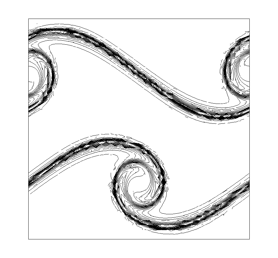
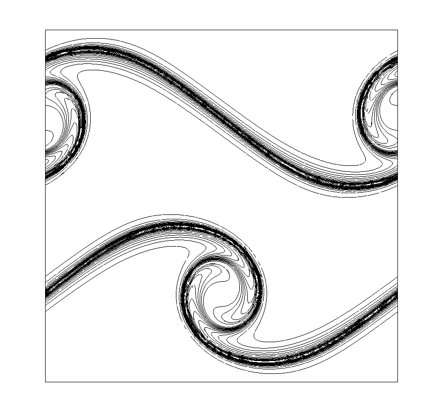
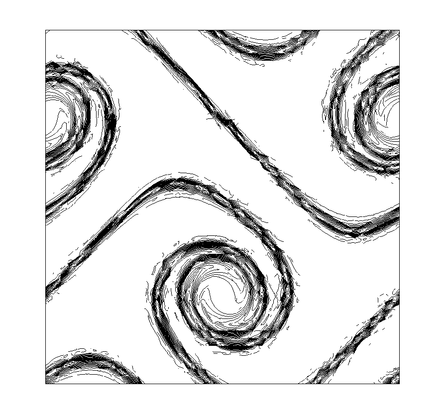
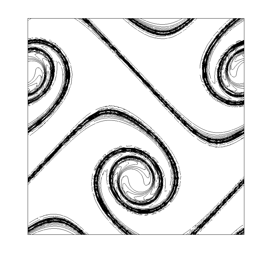
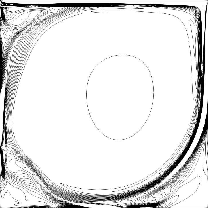
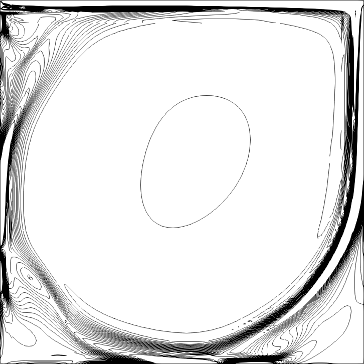
We use P3superscript𝑃3P^{3} approximation on fixed uniform unstructured triangular meshes with mesh size 2π/402𝜋402\pi/40 and 2π/802𝜋802\pi/80, see Fig. 1, and run the simulation up to time t=8𝑡8t=8. We plot the time history of total energy (square of the L2superscript𝐿2L^{2}-norm of velocity 𝒖hsubscript𝒖\boldsymbol{u}_{h}) and total enstrophy (square of L2superscript𝐿2L^{2}-norm of vorticity ωh:=h×𝒖hassignsubscript𝜔subscriptsubscript𝒖\omega_{h}:=\nabla_{h}\times\boldsymbol{u}_{h}) in Fig. 2, as well as contours of the vorticity at t=6𝑡6t=6 and t=8𝑡8t=8 in Fig. 3 to show the resolution. We can see from Fig. 2 that the energy is monotonically decreasing, with a very small dissipation error. The dissipated energy at time t=8𝑡8t=8 for the scheme on the coarse mesh is about 2×1032superscript1032\times 10^{-3}, while that on the fine mesh is about 2×1042superscript1042\times 10^{-4}. The dissipation in enstrophy is more severe, where we also observe a fluctuation, probably due to the fact that vorticity ωhsubscript𝜔\omega_{h} is a derived variable from the velocity computation. Our results are qualitatively similar to those obtained in [21] that use a vorticity-stream function formulation, with roughly a similar computational cost.
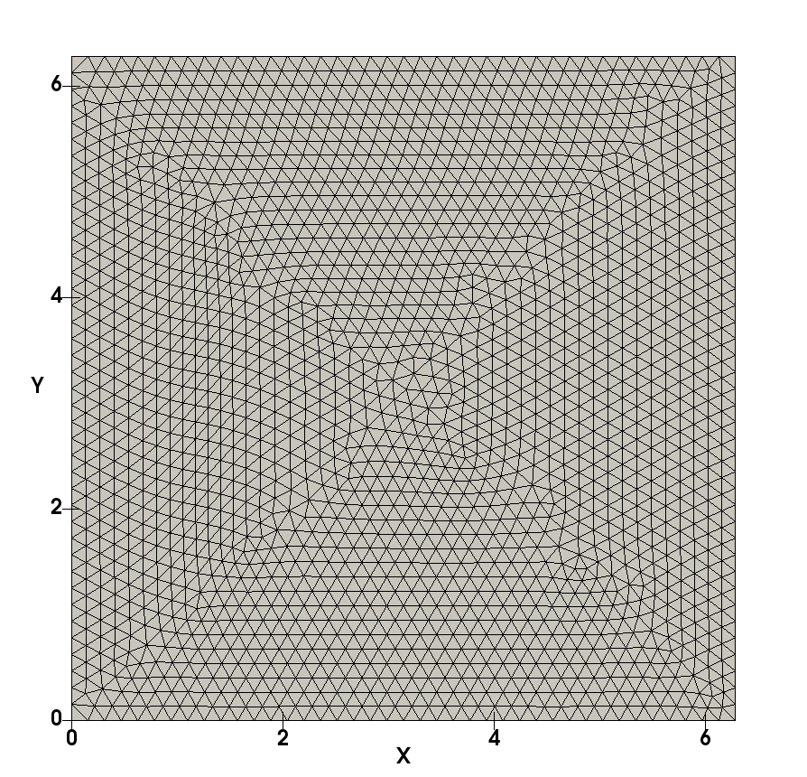
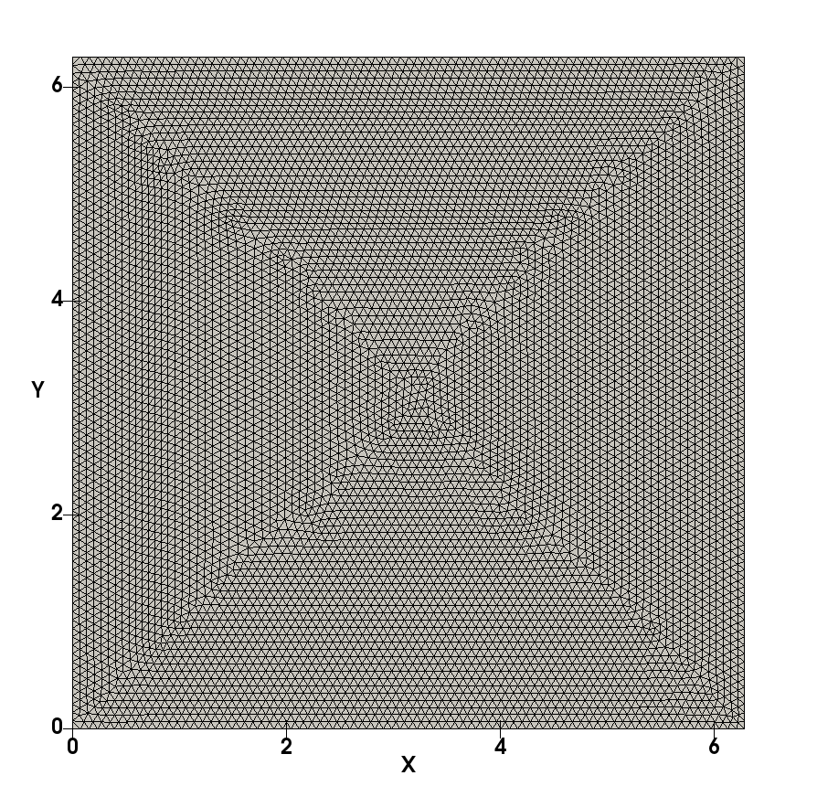
Figure 1. Example 2: the computational mesh. Left: coarse mesh. Right: fine mesh.
Refer to caption
Refer to caption
Figure 2. Example 2: the time history of energy and enstrophy.
0011122233344455566677788834.26234.26234.26234.26334.26334.26334.26434.26434.264uh(t)02superscriptsubscriptnormsubscript𝑢𝑡02||u_{h}(t)||_{0}^{2}P3,h=2π/40superscript𝑃32𝜋40P^{3},h=2\pi/40P3,h=2π/80superscript𝑃32𝜋80P^{3},h=2\pi/80
00111222333444555666777888787878797979808080timeωh(t)02superscriptsubscriptnormsubscript𝜔𝑡02||\omega_{h}(t)||_{0}^{2}P3,h=2π/40superscript𝑃32𝜋40P^{3},h=2\pi/40P3,h=2π/80superscript𝑃32𝜋80P^{3},h=2\pi/80
Figure 3. Example 2: Contour of vorticity. 30 equally spaced contour lines between 4.94.9-4.9 and 4.94.94.9. Left: results on the coarse mesh; right: results on the fine mesh. Top: t=6𝑡6t=6; bottom: t=8𝑡8t=8. P3superscript𝑃3P^{3} approximation.
Refer to caption
Refer to caption
Refer to caption
Refer to caption

Example 3: Kelvin-Helmholtz instability problem

We consider the Kelvin-Helmholtz instability problem, the set-up is taken from [28]. The Navier-Stokes equations (16) with Reynolds number Re=10000Re10000\mathrm{Re}=10000 on the domain [0,1]×[0,1]0101[0,1]\times[0,1] with a periodic boundary condition on the x𝑥x-direction, and the free-slip boundary condition 𝒖𝒏=0𝒖𝒏0\boldsymbol{u}\cdot\boldsymbol{n}=0, ν((𝒖)𝒏)×𝒏=0𝜈𝒖𝒏𝒏0\nu((\nabla\boldsymbol{u})\boldsymbol{n})\times\boldsymbol{n}=0 at y=0𝑦0y=0 and y=1𝑦1y=1. The initial conditions are taken to be

u1(x,y,0)=subscript𝑢1𝑥𝑦0absent\displaystyle u_{1}(x,y,0)= utanh((2y1)/δ0)+cnyψ(x,y),subscript𝑢tanh2y1subscript𝛿0subscript𝑐𝑛subscript𝑦𝜓𝑥𝑦\displaystyle\;u_{\infty}\mathrm{tanh((2y-1)/\delta_{0})}+c_{n}\partial_{y}\psi(x,y),
u2(x,y,0)=subscript𝑢2𝑥𝑦0absent\displaystyle u_{2}(x,y,0)= cnxψ(x,y),subscript𝑐𝑛subscript𝑥𝜓𝑥𝑦\displaystyle\;-c_{n}\partial_{x}\psi(x,y),

with corresponding stream function

ψ(x,y)=uexp((y.5)2/δ02)[cos(5πx)+cos(20πx)].𝜓𝑥𝑦subscript𝑢superscript𝑦.52superscriptsubscript𝛿02delimited-[]5𝜋𝑥20𝜋𝑥\psi(x,y)=u_{\infty}\exp\left(-(y-.5)^{2}/\delta_{0}^{2}\right)[\cos(5\pi x)+\cos(20\pi x)].

Here, δ0=1/28subscript𝛿0128\delta_{0}=1/28 denotes the vorticity thickness, u=1subscript𝑢1u_{\infty}=1 is a reference velocity and cn=103subscript𝑐𝑛superscript103c_{n}=10^{-3} is a scaling/noise factor. The scaled time t¯=δ0/ut¯𝑡subscript𝛿0subscript𝑢𝑡\bar{t}=\delta_{0}/u_{\infty}t is introduced.

We use a P4superscript𝑃4P^{4} scheme (17) with TVD-RK3 time stepping on an unstructured triangular mesh with mesh size h=1/80180h=1/80. The time step size is taken to be Δt=δ0×102Δ𝑡subscript𝛿0superscript102\Delta t=\delta_{0}\times 10^{-2}. We run the simulation till time t¯=400¯𝑡400\bar{t}=400 (a total of 40,0004000040,000 time steps). The computation is performed on a desktop machine with 2 dual core CPUs, and about 202020 hours wall clock time is used for the overall simulation.

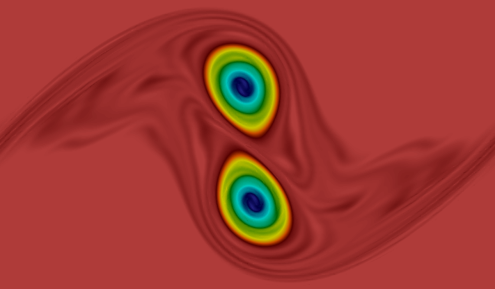
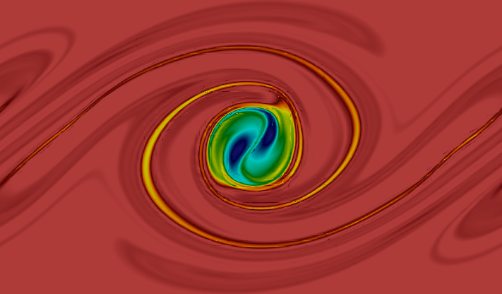
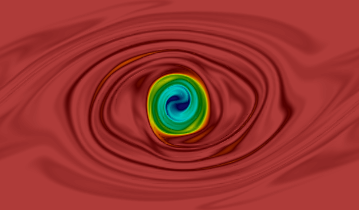
The time evolution of vortices are shown in Fig. 4 up to time t¯=200¯𝑡200\bar{t}=200. In the first row, the transition from the initial condition to the four primary vortices is shown. The four vortices are unstable in the sense that they have the tendency to merge. This is a well-known property of two-dimensional flows for which energy is transferred from the small to the large scales. We observe the second merging process is completed at around t¯=56¯𝑡56\bar{t}=56, while the last merging process completed around t¯=160¯𝑡160\bar{t}=160, and at time t¯=200¯𝑡200\bar{t}=200 a single vortex is left. Comparing with the reference data [28], computed using an IMEX SBDF2, P8superscript𝑃8P^{8} divergence-conforming HDG scheme [28] on a 256×256256256256\times 256 uniform square mesh with time step size Δt=δ0×1033.6×105Δ𝑡subscript𝛿0superscript1033.6superscript105\Delta t=\delta_{0}\times 10^{-3}\approx 3.6\times 10^{-5}, we observe quite a good agreement of the vorticity dynamics up to time t¯=56¯𝑡56\bar{t}=56 where the second merging process is completed. However, the numerical results in [28] show that the last merging appears in a much later time, at around t¯=250¯𝑡250\bar{t}=250. The numerical dissipation in our simulation triggered the last vortex merging in a much earlier time, since we use a lower order method on a coarser mesh compared with [28]. We notice that a numerical simulation at the scale of [28] is out of reach for our desktop-based simulation.
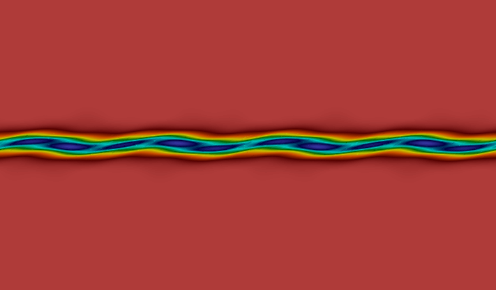
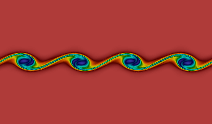
Figure 4. Example 3: Contour of vorticity ωh:=h×𝒖hassignsubscript𝜔subscriptsubscript𝒖\omega_{h}:=\nabla_{h}\times\boldsymbol{u}_{h} at (from left to right and top to bottom) time t¯={5,10,17,34,56,80,120,160,200}¯𝑡51017345680120160200\bar{t}=\{5,10,17,34,56,80,120,160,200\}.
Refer to caption
Refer to caption
Refer to caption
Refer to caption
Refer to caption
Refer to caption
Refer to caption
Refer to caption
Refer to caption
Refer to caption

In Fig. 5, we plot the evolution of kinetic energy and enstrophy of our simulation, together with the reference data provided in [28]. A good agreement of the kinetic energy can be clearly seen, while the enstrophy agrees pretty well till time t¯=150¯𝑡150\bar{t}=150, where the last vortex merging toke place for our simulation, while that happens at a much later time t¯=250¯𝑡250\bar{t}=250 for the scheme used in [28].

Figure 5. Example 3: the time history of energy and enstrophy.
005050501001001001501501502002002002502502503003003003503503504004004000.480.480.480.4810.4810.4810.4820.4820.482time unit t¯=t×u/δ0¯𝑡𝑡subscript𝑢subscript𝛿0\overline{t}=t\times u_{\infty}/\delta_{0}12uh(t)0212superscriptsubscriptnormsubscript𝑢𝑡02\frac{1}{2}||u_{h}(t)||_{0}^{2}ref. [28]P4𝑃4P4, h=1/80
00505050100100100150150150200200200250250250300300300350350350400400400202020252525303030353535time unit t¯=t×u/δ0¯𝑡𝑡subscript𝑢subscript𝛿0\overline{t}=t\times u_{\infty}/\delta_{0}12ωh(t)0212superscriptsubscriptnormsubscript𝜔𝑡02\frac{1}{2}||\omega_{h}(t)||_{0}^{2}ref. [28]P4𝑃4P4, h=1/80

Example 4: flow around a cylinder

We consider the 2D-2 benchmark problem proposed in [26] where a laminar flow around a cylinder is considered. The domain is a rectangular channel without an almost vertically centered circular obstacle, c.f. Fig. 6,

Ω:=[0,2.2]×[0,0.41]\{(x,y)(0.2,0.2)20.05}.assignΩ\02.200.41subscriptnorm𝑥𝑦0.20.220.05\Omega:=[0,2.2]\times[0,0.41]\backslash\{\|(x,y)-(0.2,0.2)\|_{2}\leq 0.05\}.

The boundary is decomposed into Γin:={x=0}assignsubscriptΓ𝑖𝑛𝑥0\Gamma_{{in}}:=\{x=0\}, the inflow boundary, Γout:={x=2.2}assignsubscriptΓ𝑜𝑢𝑡𝑥2.2\Gamma_{{out}}:=\{x=2.2\}, the outflow boundary, and Γwall:=Ω\(ΓinΓout)assignsubscriptΓ𝑤𝑎𝑙𝑙\ΩsubscriptΓ𝑖𝑛subscriptΓ𝑜𝑢𝑡\Gamma_{{wall}}:=\partial\Omega\backslash(\Gamma_{{in}}\cup\Gamma_{{out}}), the wall boundary. On ΓoutsubscriptΓ𝑜𝑢𝑡\Gamma_{{out}} we prescribe natural boundary conditions (ν𝒖+pI)𝒏=0𝜈𝒖𝑝𝐼𝒏0(-\nu\nabla\boldsymbol{u}+pI)\boldsymbol{n}=0, on ΓwallsubscriptΓ𝑤𝑎𝑙𝑙\Gamma_{{wall}} homogeneous Dirichlet boundary conditions for the velocity (no-slip) and on ΓinsubscriptΓ𝑖𝑛\Gamma_{{in}} the inflow Dirichlet boundary conditions

𝒖(0,y,t)=6u¯y(0.41y)/0.412(1,0),𝒖0𝑦𝑡6¯𝑢𝑦0.41𝑦superscript0.41210\boldsymbol{u}(0,y,t)=6\bar{u}\,y(0.41-y)/0.41^{2}\cdot(1,0),

with u¯=1¯𝑢1\bar{u}=1 the average inflow velocity. The viscosity is taken to be ν=103𝜈superscript103\nu=10^{-3}, hence Reynolds number Re=u¯D/ν=100Re¯𝑢𝐷𝜈100\mathrm{Re}=\bar{u}D/\nu=100, where D=0.1𝐷0.1D=0.1 is the disc diameter.

The quantities of interest in this example are the (maximal and minimal) drag and lift forces cD𝑐𝐷cD , cL𝑐𝐿cL that act on the disc. These are defined as

[cD,cL]=1u¯2rΓo(ν𝒖pI)𝒏ds,subscript𝑐𝐷subscript𝑐𝐿1superscript¯𝑢2𝑟subscriptsubscriptΓ𝑜𝜈𝒖𝑝𝐼𝒏ds[c_{D},c_{L}]=\frac{1}{\bar{u}^{2}r}\int_{\Gamma_{o}}(\nu\nabla\boldsymbol{u}-pI)\boldsymbol{n}\mathrm{ds},

where r=0.05𝑟0.05r=0.05 is the radius of the obstacle, and ΓosubscriptΓ𝑜\Gamma_{o} denotes the surface of the obstacle.

We use a (curved) unstructured triangular grid around the disk. In Fig. 6 the geometry, the mesh and a typical solution is depicted. The final time of the simulation is taken to be t=8𝑡8t=8. The mesh consists of 488 triangular elements with mesh size h0.0130.013h\approx 0.013 around the circle (24 uniformly spaced nodes on the circle), and h0.080.08h\approx 0.08 away from the circle. We run the simulation on this mesh using polynomial degree form 222 to 444. The maximal/minimal drag and lift coefficients are lists in Table 3, where the local dofs refer to those for velocity and pressure, while the global dofs refer to those for the Lagrange multiplier on the mesh skeleton. As a reference, we also show the results obtained by FEATFLOW [12] using a Q2/P1,discsuperscript𝑄2superscript𝑃1discQ^{2}/P^{1,\mathrm{disc}} quadrilaterial element. Clearly we observe a rapid convergence as the polynomial degree increases. Compared with the (low-order) results form the literature [12], the same accuracy is achieved with a lot less degrees of freedom. Similar observation was also found for the the divergence-conforming IMEX-HDG scheme [20].

Figure 6. Example 4: Sketch of the mesh and the solution using the P4superscript𝑃4P^{4} scheme (color corresponding to velocity magnitude 𝒖2subscriptnorm𝒖2\|\boldsymbol{u}\|_{2}).
Refer to caption
Refer to caption
Table 3. Example 4: Maximal/minimal values of lift and drag coefficients: results for different polynomial degree.
##\#dof
local
##\#dof
global
maxcDsubscript𝑐𝐷\max c_{D} mincDsubscript𝑐𝐷\min c_{D} maxcLsubscript𝑐𝐿\max c_{L} mincLsubscript𝑐𝐿\min c_{L}
k=2 5 368 2 316 3.132939 3.074858 0.935284 -0.884771
k=3 7 808 3 088 3.229686 3.170424 0.969323 -0.965982
k=4 10 736 3 860 3.226865 3.163545 0.986497 -1.018691
ref. [12] - 167 232 3.22662 3.16351 0.98620 -1.02093
- 667 264 3.22711 3.16426 0.98658 -1.02129

Example 5: lid driven cavity at a high Reynolds number

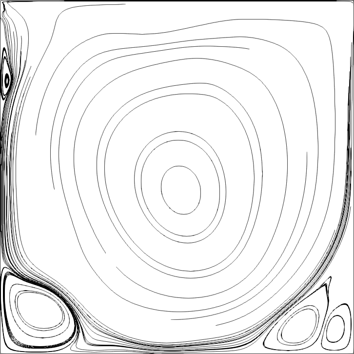
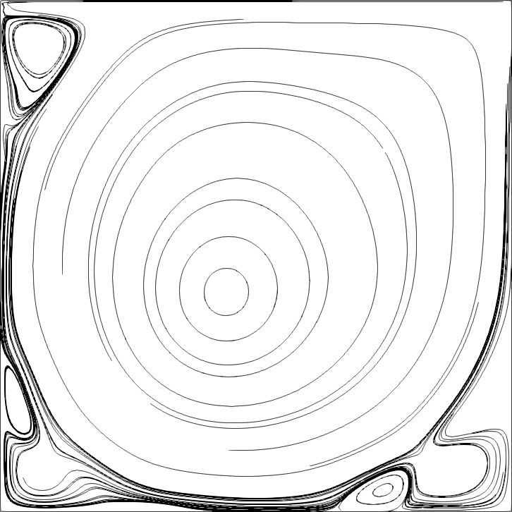
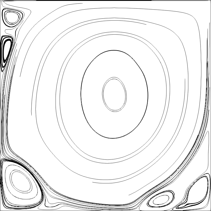
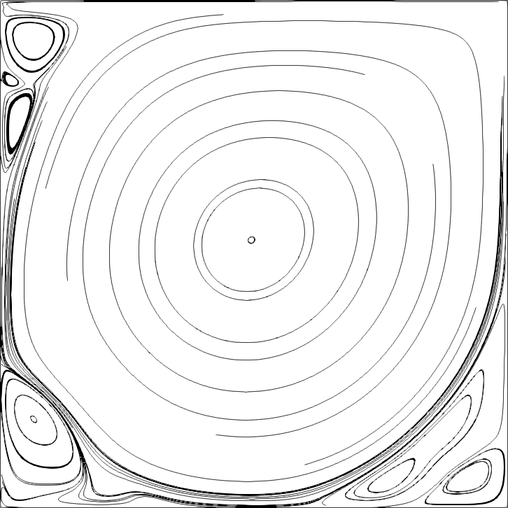
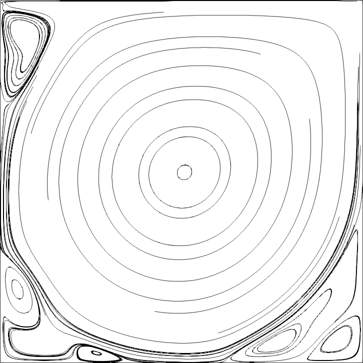
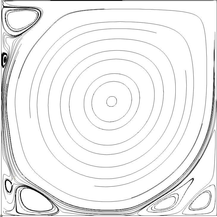
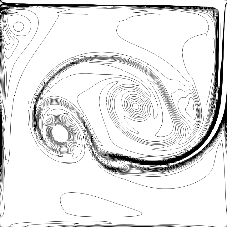
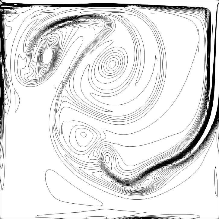
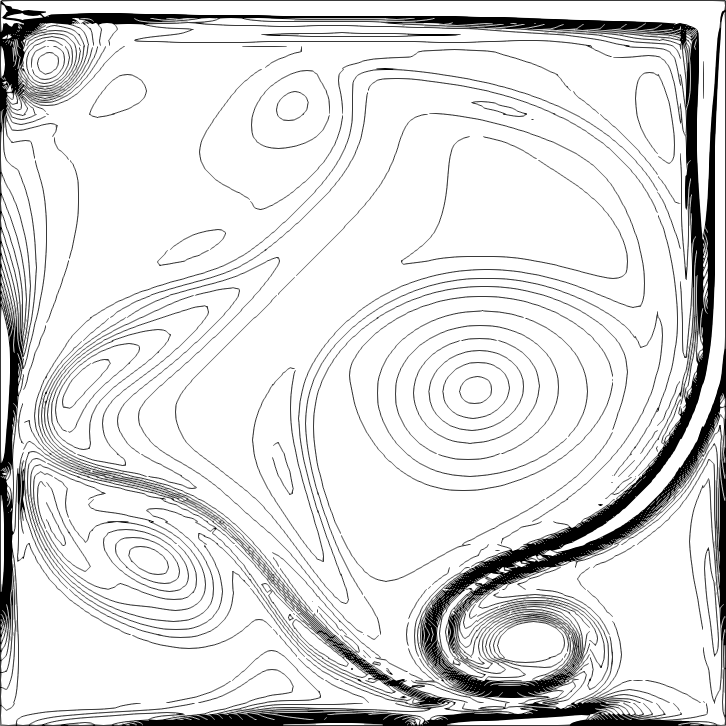
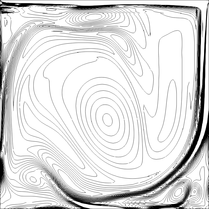
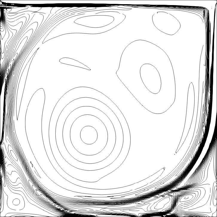
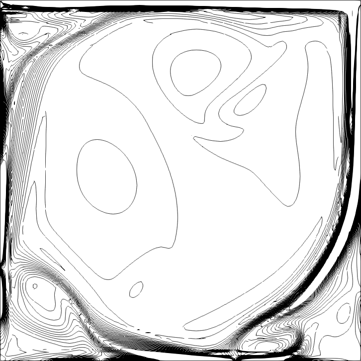
In our last example, we consider a lid driven cavity flow problem [13] at a high Reynolds number Re=10,000Re10000\mathrm{Re}=10,000. The domain is a unit square Ω=[0,1]×[0,1]Ω0101\Omega=[0,1]\times[0,1], the velocity boundary condition is used on the boundary with (u1,u2)=(1,0)subscript𝑢1subscript𝑢210(u_{1},u_{2})=(1,0) on the top boundary y=1𝑦1y=1, and (u1,u2)=(0,0)subscript𝑢1subscript𝑢200(u_{1},u_{2})=(0,0) on the other boundaries. We use a steady-state Solver solver to generate the initial condition. For this problem, the solution eventually reaches a steady state. However, for such high Reynolds number flow, the numerical solution tend to oscillate around the steady-state without settling done on coarse meshes, see e.g. the discussion in [11].

We consider a uniform 32×32323232\times 32 rectangular mesh using the divergence-free RT Q4superscript𝑄4Q^{4} velocity space. Since temporal accuracy is not of concern for this problem. We use the cheaper forward Euler time stepping (9). The time step size is taken to be Δt=103Δ𝑡superscript103\Delta t=10^{-3}. Final time of simulation is t=400𝑡400t=400. Hence, a total of 400,000400000400,000 time steps is used. For this problem, we have local dofs 37,8883788837,888(local velocity and pressure) and global dofs 10,5601056010,560(Lagrange multiplier). The overall wall computational time is about 10 hours.

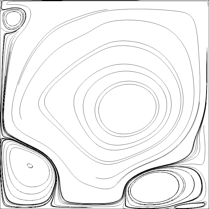
In Fig. 7 and Fig. 8, we plot the time evolution of the streamlines and vorticity contours. We numerically observe that starting around time t=80𝑡80t=80, the solution oscillates around the steady-state solution but never reaches the steady state. The L2superscript𝐿2L^{2}-norm of the velocity difference at two consecutive time levels hangs at around 5×1055superscript1055\times 10^{-5} and never drops down. This phenomenon is probably due to the low mesh resolution (32×32323232\times 32 in our case). In particular, for second-order methods, a mesh larger than 256×256256256256\times 256 shall be used to reach a steady-state for high Reynolds number flow (Re>10,000𝑅𝑒10000Re>10,000); see [11]. However, the main features of the small structure around the top, left and right corners can be be clearly seen in Fig. 7 and Fig. 8 starting at time t=80𝑡80t=80. Finally, in Fig. 9, we plot the x𝑥x-component of velocity field along the horizontal central line x=0.5𝑥0.5x=0.5, and the y𝑦y-component of velocity field along the vertical central line y=0.5𝑦0.5y=0.5 at time t=160,200,400𝑡160200400t=160,200,400, along with the reference data provided in [13]. A good match with the reference data is observed.
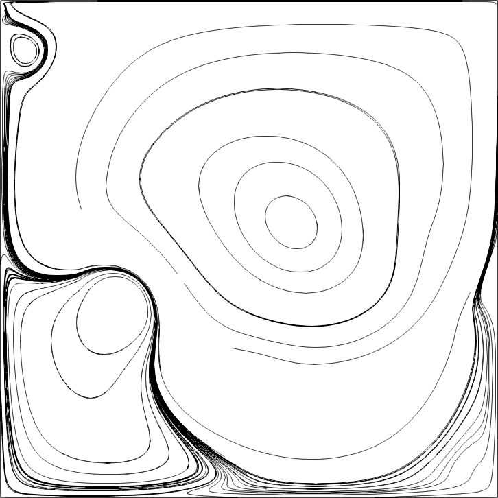
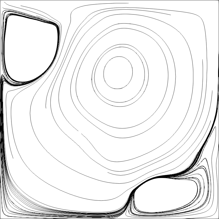
Figure 7. Example 5: Streamline plots at (form left to right and top to bottom) time t={2,4,10,20,40,80,160,200,400}𝑡2410204080160200400t=\{2,4,10,20,40,80,160,200,400\}.
Refer to caption
Refer to caption
Refer to caption
Refer to caption
Refer to caption
Refer to caption
Refer to caption
Refer to caption
Refer to caption
Figure 8. Example 5: Contour of vorticity at (form left to right and top to bottom) time t={2,4,10,20,40,80,160,200,400}𝑡2410204080160200400t=\{2,4,10,20,40,80,160,200,400\}. 30 equally spaced contours between 11-1 to 111.
Refer to caption
Refer to caption
Refer to caption
Refer to caption
Refer to caption
Refer to caption
Refer to caption
Refer to caption
Refer to caption
Figure 9. Example 5: velocity along cut lines. Top: x𝑥x-component velocity on horizontal central line x=0.5𝑥0.5x=0.5; bottom: y𝑦y-component velocity on vertical central line y=0.5𝑦0.5y=0.5.
0.10.1-0.1000.10.10.10.20.20.20.30.30.30.40.40.40.50.50.50.60.60.60.70.70.70.80.80.80.90.90.91111.11.11.10.50.5-0.5000.50.50.5111y𝑦yu𝑢uref. [13]t=160𝑡160t=160t=200𝑡200t=200t=400𝑡400t=400
0.10.1-0.1000.10.10.10.20.20.20.30.30.30.40.40.40.50.50.50.60.60.60.70.70.70.80.80.80.90.90.91111.11.11.10.50.5-0.5000.50.50.5x𝑥xv𝑣vref. [13]t=160𝑡160t=160t=200𝑡200t=200t=400𝑡400t=400

5. Conclusion

We presented an explicit divergence-free DG method for incompressible flows. The key ingredient for the efficient implementation is the identification of the equivalence of the mass matrix inversion of the divergence-free finite element space and a hybrid-mixed Poisson solver. The scheme is especially suitable for unsteady inviscid flow or viscous flow at a high Reynolds number flow.

References

  • [1] D. N. Arnold and F. Brezzi, Mixed and nonconforming finite element methods: implementation, postprocessing and error estimates, RAIRO Modél. Math. Anal. Numér., 19 (1985), pp. 7–32.
  • [2] D. N. Arnold, F. Brezzi, B. Cockburn, and L. D. Marini, Unified analysis of discontinuous Galerkin methods for elliptic problems, SIAM J. Numer. Anal., 39 (2001/02), pp. 1749–1779.
  • [3] D. N. Arnold, R. S. Falk, and R. Winther, Finite element exterior calculus, homological techniques, and applications, Acta Numer., 15 (2006), pp. 1–155.
  • [4] U. M. Ascher, S. J. Ruuth, and R. J. Spiteri, Implicit-explicit Runge-Kutta methods for time-dependent partial differential equations, Appl. Numer. Math., 25 (1997), pp. 151–167. Special issue on time integration (Amsterdam, 1996).
  • [5] J. B. Bell, P. Colella, and H. M. Glaz, A second-order projection method for viscous, incompressible flow, in AIAA 8th Computational Fluid Dynamics Conference (Honolulu, HI, 1987), AIAA, Washington, DC, 1987, pp. 789–794.
  • [6] F. Brezzi, J. Douglas, Jr., and L. D. Marini, Two families of mixed finite elements for second order elliptic problems, Numer. Math., 47 (1985), pp. 217–235.
  • [7] M. P. Calvo, J. de Frutos, and J. Novo, Linearly implicit Runge-Kutta methods for advection-reaction-diffusion equations, Appl. Numer. Math., 37 (2001), pp. 535–549.
  • [8] B. Cockburn, G. Kanschat, and D. Schötzau, A note on discontinuous Galerkin divergence-free solutions of the Navier-Stokes equations, J. Sci. Comput., 31 (2007), pp. 61–73.
  • [9] W. E and J.-G. Liu, Vorticity boundary condition and related issues for finite difference schemes, J. Comput. Phys., 124 (1996), pp. 368–382.
  • [10]  , Finite difference methods for 3D viscous incompressible flows in the vorticity-vector potential formulation on nonstaggered grids, J. Comput. Phys., 138 (1997), pp. 57–82.
  • [11] E. Erturk, Discussions on driven cavity flow, Internat. J. Numer. Methods Fluids, 60 (2009), pp. 275–294.
  • [12] FEATFLOW, Finite element software for the incompressible navier-stokes equations, www.featflow.de.
  • [13] U. Ghia, N. Ghia, and C. T. Shin, High-Re Solutions for Incompressible Flow Using the Navier-Stokes Equations and a Multigrid Method, J. Comput. Phys., 48 (1982), pp. 387–411.
  • [14] R. Glowinski, Finite element methods for incompressible viscous flow, in Handbook of numerical analysis, Vol. IX, Handb. Numer. Anal., IX, North-Holland, Amsterdam, 2003, pp. 3–1176.
  • [15] J. L. Guermond, P. Minev, and J. Shen, An overview of projection methods for incompressible flows, Comput. Methods Appl. Mech. Engrg., 195 (2006), pp. 6011–6045.
  • [16] J. Guzmán, C.-W. Shu, and F. A. Sequeira, H(div)Hdiv\rm H(div) conforming and DG methods for incompressible Euler’s equations, IMA J. Numer. Anal., 37 (2017), pp. 1733–1771.
  • [17] V. John, A. Linke, C. Merdon, M. Neilan, and L. G. Rebholz, On the divergence constraint in mixed finite element methods for incompressible flows, SIAM Rev., 59 (2017), pp. 492–544.
  • [18] C. A. Kennedy and M. H. Carpenter, Additive Runge-Kutta schemes for convection-diffusion-reaction equations, Appl. Numer. Math., 44 (2003), pp. 139–181.
  • [19] C. Lehrenfeld, Hybrid Discontinuous Galerkin methods for solving incompressible flow problems, 2010. Diploma Thesis, MathCCES/IGPM, RWTH Aachen.
  • [20] C. Lehrenfeld and J. Schöberl, High order exactly divergence-free hybrid discontinuous galerkin methods for unsteady incompressible flows, Computer Methods in Applied Mechanics and Engineering, 307 (2016), pp. 339–361.
  • [21] J.-G. Liu and C.-W. Shu, A high-order discontinuous Galerkin method for 2D incompressible flows, J. Comput. Phys., 160 (2000), pp. 577–596.
  • [22] Y. Maday, A. T. Patera, and E. M. Rø nquist, An operator-integration-factor splitting method for time-dependent problems: application to incompressible fluid flow, J. Sci. Comput., 5 (1990), pp. 263–292.
  • [23] A. Montlaur, S. Fernandez-Mendez, J. Peraire, and A. Huerta, Discontinuous Galerkin methods for the Navier-Stokes equations using solenoidal approximations, Internat. J. Numer. Methods Fluids, 64 (2010), pp. 549–564.
  • [24] P. A. Raviart and J. M. Thomas, A mixed finite element method for second order elliptic problems, in Mathematical Aspects of Finite Element Method, Lecture Notes in Math. 606, I. Galligani and E. Magenes, eds., Springer-Verlag, New York, 1977, pp. 292–315.
  • [25] S. Zaglmayr, High order finite element methods for electromagnetic field computation, 2006. PhD thesis, Johannes Kepler Universit ät Linz, Linz.
  • [26] M. Schäfer, S. Turek, F. Durst, K. E., and R. R., Benchmark computations of laminar flow around a cylinder, Flow simulation with high-performance computers II 1996; :547–566.
  • [27] J. Schöberl, C++11 Implementation of Finite Elements in NGSolve, 2014. ASC Report 30/2014, Institute for Analysis and Scientific Computing, Vienna University of Technology.
  • [28] P. W. Schroeder, V. John, P. L. Lederer, C. Lehrenfeld, G. Lube, and J. Schöberl, On reference solutions and the sensitivity of the 2d Kelvin–Helmholtz instability problem, arXiv preprint arXiv:1803.06893, (2018).
  • [29] C.-W. Shu and S. Osher, Efficient implementation of essentially nonoscillatory shock-capturing schemes, J. Comput. Phys., 77 (1988), pp. 439–471.