Micromechanical model for sintering and damage in viscoelastic porous ice and snow. Part I: Theory.
Abstract
Ice and snow have sometime been classified as a viscoelastic or viscoplastic material according to temperature, strain rate, pressure and time scale. Throughout experimental studies presented in the literature, it has been observed that at very low temperatures or high strain rate, porous ice and snow exhibit brittle behavior, but experience high viscous and plastic flow at temperatures closed to the melting point and low rates. At the macroscopic level nonlinearity is not necessarily attributed to material level permanent changes or yielding but mainly to micro cracks, porosity collapse and crack propagation. This paper attempts to address this complex behavior with a full microstructure based model.
keywords:
Microstructure , viscoelasticity , particle method , fracture , beamsMSC:
[2010] 74M25, 99-001 Introduction
Several engineering experts attempted to simulate snow behavior for different applications such as movies, avalanche protection and prediction, ski, tires, civil infrastructures. Snow is an heterogeneous media. Simulating and modeling its mechanical response at large scale require a detailed analysis. Such analysis can be done in three steps. The first step concerns the design and validation of mathematical model of small length and time scales describing the grain scale behavior and including most of relevant micro-mechanical processes. Static and dynamic properties including frequency and rate dependency are studied and modeled. secondly the small length and time scales model is used to link numerical simulation with meso-scale mechanical behavior of laboratory scales representative volumes. Third a macro-scale model is set with less complexity for simulating the large structure response. For most material, the first step can be skipped as only homogenized version of the true representative volumes is considered. However given the structure dependent mechanical response and the fracture properties of snow it is difficult to reach realistic modeling without this step. The conditions of interest in this study are slow, rapid and large deformation for which thermodynamic state of the material is important. The main objective of the presented model is to provide a reliable simulation tool for investigating the non-linearity, rate, load and temperature dependent mechanical response of snow with complex boundary and loading conditions in engineering. Two phases of snow are considered: the granular phase in which snow is an aggregation of contacting granules and the continuum phase a solid porous ice media. In the granular phase, ice grains are free to move and particles are characterized trough frictional and inelastic contact. In the continuum phase grains are bonded in a melting and re-crystallization cycle and form together a solid structure. The difficulty lay in capturing the geometry with accuracy and its evolution caused by slow or rapid processes at different time scales. The slow processes known as metamorphism include a melting and appreciable flow of a liquid phase followed by crystallization or a diffusion sintering driven by energy minimization. These processes are classified into three categories according to the temperature gradient: the equilibrium metamorphism (Equi-temperature) that turns the initial crystal into rounded, kinetic metamorphism that creates faceted grains and melt-freeze metamorphism for large round grains [1, 2, 3]. The temperature gradient is behind formation of layers of different strength. A weak layer lead to high risk of avalanche in a snow pack. The rapid processes include mechanical rearrangement of grains, fracture and pressure sintering caused by external forces. This paper presents the short time scale behavior of snow with exception of wet snow. A coupled micro-beam lattice model and discrete particle model is proposed.
2 Modeling sintering effect of in snow dynamics
2.1 Free sintering and pressure sintering
Snow behavior is characterized by fracture, creep, and the dimensions of its constrictions (bond between grains) created through sintering. The bonding and adhesion of ice have been largely studied in the past. Some effort were made to characterize the adhesive forces between bonded ice particles at different sintering time and temperature. When two spherical ice grains were brought in contact they became quickly bonded [4, 5, 6, 7, 8, 9, 10]. This phenomenon was first documented by Faraday [4] in 1850 who noticed that two ice blocks became one when brought into contact. Most of experiments performed at large time scale (few minutes to days) showed that the neck growth can be attributed to mass transport to the contact area. These experiments showed a temperature dependent growth with a very rapid growth temperatures close to the melting point. However, separate studies show that sintering also happen at shorter time scale when the contact interface is under pressure. The shape of the bond are different, given the fact that the diffusion sintering is mainly caused by mass transport to the neck while the pressure sintering happen by increasing contact area through deformation (figure 1). Processes in both pressure and diffusion sintering are largely attributed to the presence of a quasi-liquid layer on the ice boundary [11, 5, 12] [13] or the melting of the interface [8]. The thin quasi-liquid layer is almost always created at the surface of ice or water in an attempt to reduce the free energy, as surface ions change their electron distribution [11]. The thickness of the liquid layer was estimated to be around 10 nanometers [11] ie. Fletcher measured to [13] between and and Jellinek at [12].

Some quantitative studies presenting the effect of pressure in the initial stage of the sintering have emerged in the last decades [8, 10]. The pressure sintering is mainly due to regelation, a melting and freezing process by variation of the melting point according to the pressure. Ice regelation was first documented in a quantitative study carried by J. Thomson and W. Thomson [14] who called into question Faraday’s quasi-liquid layer theory. Regelation is caused by an increase of pressure followed by a decrease attributable to variation of external forces, relaxation, progressive increase of surface area, local melting of asperities …. When passing from compression to tension, the liquid portion previously melted by pressure plus the portion from the quasi-liquid layer accumulated at the contact area freeze back and resist to the tension. Some portion of liquid for instance melted of asperities and liquid layer freeze while still under compression when the contact interface is widened by time dependent deformation. Experiments have shown that after fracture of the bond, the new surfaces of both particles recover.
2.2 Bond growth and evolution of porous structure
In the light of the above assumptions, the load carrying capacity of bonds created by pressure sintering can be calculated in two components. A first component being pressure independent is composed of resistance arising from rapid freezing of quasi-liquid layer at the contact and quasi-instantaneous capillary attraction [4]. This component is present for both pressure and diffusion sintering. The second component which is pressure , time and temperature dependent originates from contact interface being welded by melting and freezing. The later dependents on mechanical properties of ice and the loading condition.
| (1) |
Pressure sintering cannot account for total adhesive forces experienced in ice-ice contact [12]. However for short time scale, or appreciable pressure, the pressure dependent adhesive force is dominant. This was proved in the experiments performed by Nakaya [5], where cohesion increased more than ten time when the contact force was increased by ten. Since our focus is the short time scale only pressure sintering is considered. Diffusion caused neck growth are not considered throughout the simulation though initial micro-structures can be taken from any stage of the metamorphism. In order to apprehend the mechanical behavior of the complex structures resulting from pressure sintering, the structure of porous ice or snow is represented by discrete particles and bonded virtually by massless cylindrical beams. The ice grains are the particles and have frictional contact properties while the constrictions in the ice matrix are the beams connecting particle pairs [15]. When the structure loses all its bonds it become granular media and can go back to its porous solid structure if given enough time and pressure to sinter again. Stress state at the contact area determines which framework is considered for assessing the mechanical response to external loads. For compressive stresses below the compressive strength, a time dependent bond growth or re-bonding mechanism due to visco-plasticity and melt-freeze mechanism occur. The growth of the bond area is directly linked to the viscous and plastic deformation of the ice particles and their equivalent radius as shown in equation 2.
| (2) |
For torques, tensile and shear stresses, there is viscoelastic deformation accompanied by quasi-brittle fracture of the bonds. The micro-structure evolution is represented by coupling discrete particle model for the first mechanism and a lattice of Euler-Bernoulli micro-beam with fracture properties for the latter. The previous description applies to solid phase. When there is no bond or negligible bond radius i.e granular phase torques and shear resistance are computed according to frictional contact between particles. This conceptual model is consistent with the creep, collapse and flow mechanisms discussed in [16].
2.3 Viscoelasticity of Ice and snow
Under specific modeling constrains and for the sake of simplicity ice can be considered elastic. However, the conditions under which ice exhibits pure elasticity are so restricted and can hardly be met in real life [17]. Attempts to characterize ice by means of young modulus under static experiments resulted in wide range of values with one order of magnitude difference [18]. Measurement using high frequency are considered more reliable. Several researcher concluded that plasticity can be observed under any stress and the elastic limit is usually assumed to be null, similar to viscoelastic materials. The similarity of ice and viscous fluid has been pointed out by observation of glaciers flow and ice creep in laboratory. Figure 2 shows laboratory measurement of secondary creep rate of ice [19] according to the stress.
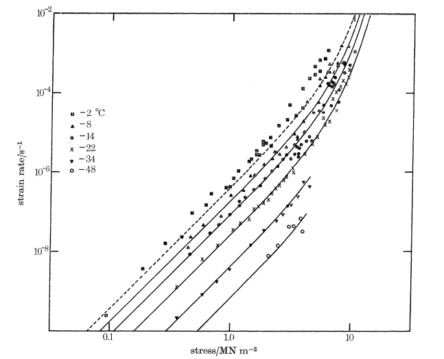
Pure elastic behavior of ice can be obtained at high strain rate[20] and hydrostatic compression of a single crystal [17]. The main cause of viscous behavior in ice is its crystalline structure. Ice is generally found under polycrystalline form which is composed of single crystalline plates the order of magnitude of micrometer thick [17]. In deed a single ice crystal can be characterized as elasto-plastic. Since polycrystalline ice is formed by plates the deformation is also dependent to the orientation of the crystals according to the applied stress. The deformation and creep of polycrystalline ice is characterized by basal dislocations gliding of ice crystals along the basal planes [19]. For randomly oriented crystals, deformation is accompanied by bending and shearing of the crystals. Since ice is often found at temperature closed to its melting point, its behavior is dominated by creep flow. The creep of ice is divided into tree stages. First stage is the transient creep characterized by a high strain rate that decreases rapidly to a limit. The limit is the secondary or steady state creep that is followed by tertiary creep which leads to failure. The decrease of strain rate during transient creep is about 2 order of magnitude [21]. Most of the strain caused during transient creep is recoverable. The transient creep plays a significant role in ice and snow dynamics. Therefore for limited time, ice can be considered as a non-Newtonian viscoelastic fluid [16].
3 Integrated model for ice and snow dynamics
The model developed in this paper is a coupling between discrete particles method and damageable Euler-Bernouli beams lattice of grain scale to yield viscoplastic behavior at the macroscopic level. The compressive behavior of ice grains is described by a linear viscoelastic contact model with different creep mechanisms. Despite the fact that nonlinear models have been used to include secondary creep, it has been found that secondary creep is rarely obtained under limited time of observation and that tertiary creep usually happens during the transient creep for high stresses [22]. Under shear, tension, bending and torsion, we use a viscoelastic quasi-brittle beam model for bonded grains and an elastic perfectly-plastic law for detached grains.
3.1 Elasticity and creep mechanics for compressive loads
Using Boltzmann principle and assuming linear viscoelasticity of ice, the displacement can be divided into three independent parts (figure 3) in the displacement-time curve for constant loads similar to a Burger’s material.

The first part of the displacement represents the amount of displacement attributed to instantaneous elastic response. After the load is removed, vanishes almost immediately. Then, a delayed displacement is gradually recovered. Finally, long after the load removal, a permanent displacement representing a Newtonian flow remains. This behavior usually represented by Burger’s constitutive model is a series combination of Kelvin and Maxwell models (figure 4). and are calculated from the Maxwell element and from the Kelvin element.

For the compressive behavior, we consider rate and loading history dependent equation of Burger’s material [23, 24, 16] in the following force-displacement relation:
| (3) |
Where and are the instantaneous viscosity and stiffness constants, and the delayed viscosity and stiffness constants, and are the first and second derivatives of the displacement. The instantaneous stiffness can be obtained from the young modulus if measured at high strain rate.
The equation is numerically solved for the normal force using the central finite difference scheme in the following order [25]:
| (4) |
The same procedure is applied to determine the tangential force in the absence of bonds by converting each of the four parameters into transverse their transverse values:
| (5) |
being the poison ratio.
3.1.1 Creep and Dynamical response
The four parameters in (3) can be obtained trough creep test with a compressive impulsion :
| (6) |
| (7) |
The response described in (3) can be reduced to the following using Laplace transformation :
| (8) |
The displacement in the two sections of the Kelvin element are identical and equal to the total delayed displacement. The total delayed displacement is recovered exponentially over time at a rate called relaxation time: . The creep rate is the time derivative of the creep:
| (9) |
Note that the creep rate is the sum of the transient or primary creep rate and the steady-state or stationary creep rate . The transient creep is always present in ice [22] and is well suited by the Burger’s model. However Burger’s model is only suitable for short time scale [26] and poorly fit the long term and steady state creep. The longterm behavior may be captured using a nonlinear maxwell dash-pot. The model is also suited for dynamic behavior and response at much smaller time scale than quasi-static conditions.
Many cases in engineering include dynamic stress or very short contact time (of order of microseconds) between particles. The response under such conditions can well be described in frequency domain. The equation (3) can be written in frequency domain in algebraic form using Lapace transform:
| (10) |
so that :
| (11) |
A sinusoidal loading of frequency leads to a phase shifted oscillatory displacement of frequency :
| (12) |
| (13) |
Where is the phase angle. This can be rewritten in the complex domain :
| (14) |
| (15) |
The complex compliance is:
| (16) |
The phase angle , dynamic compliance , storage and loss compliances representing respectively the angle between force and displacement axis, the modulus, real and imaginary part of can be expressed as:
| (17) |
| (18) |
| (19) |
| (20) |
The four viscoelastic parameters can also be obtained by fitting equation 16 and 18 to data from dynamic mechanical analysis or oscillatory shear rheometry.
3.2 Quasi-brittle fracture and collapse mechanics
3.2.1 Bond model
The collapse in ice matrix is described by damageable bond network representing the constrictions in the ice matrix. Since constrictions are the weakest sections in the snow volume [27] they are expected to fail before any damageable stress is reached in the ice grains. Also, because they present small time to failure and designed for ( shear, tension and relative rotations) loading conditions, the maxwell unit in the model for compression is omitted [23] for bonds. On the macroscopic level, the bonds between ice particles represent the majority of the constrictions in a snow mass. Therefore, bonds created trough sintering are approximated by cylindrical beams which sections are approximately equal to the area of the constrictions. It was observed that elastic-brittle bonds were only suitable for fracture in large structures similar to Linear Fracture Mechanics (LEFM) but have limitations in small size structures. This issue was addressed recently by many investigators [28, 29, 30, 31, 32] who used bonded particles to analyses fracture of small and medium size structures of quasi-brittle materials. Some softening laws have been introduced to redress the overestimation of liberated kinetic energy after fracture of brittle bonds. These laws include bilinear [29] exponential [32] cohesive residual strength beyond the yield point of the material. Furthermore the brittleness in numerical simulation is proportional to the chosen particle size [30]. The exponential softening law is in the form of :
| (21) |
Where , is the fracture energy, is the limit force for a specimen with strength .
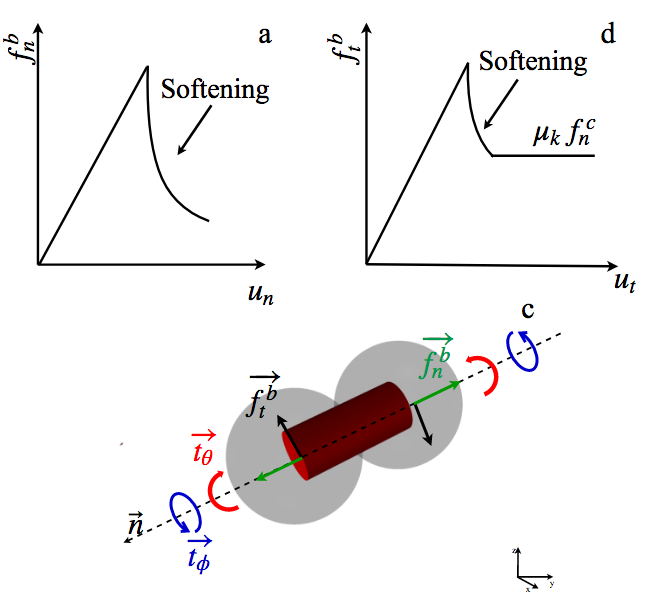
The general equation of a homogeneous beam under dynamic load can be formulated as a function strains and distortions using Euler-Lagrange equations :
| (22) |
| (23) |
Where and are the unbalanced normal and transverse loads, and the normal and transverse displacement, is the relative spin along the normal direction or twisting angle and the bending angle. and are the angular velocities. The parameters , , and are the Kelvin elastic moduli and viscosities of ice in normal and shear direction. The Saint-Venant assumptions is considered for the twist about neutral axis or shear center (torsion) neglecting the warping torsional moment. Under compression, the resulting bonding beam start thickening and the bond area increases. When loaded, the resistance forces and torques of the bond are calculated as follow :
| (24) |
After fracture fracture of a bond, softening functions are used to dissipate energy until the fracture energy is considerably released :
| (25) |
, , are respectively the elastic limit of displacement, twist angle and bending angle. and are the shear and normal strength.
The length of the beam is the distance between the center of mass of the particles and the bond area is equal to the contact area :
A local coordinate is used for the pair particles, while the shear force and bending moment are stored in the global coordinate. The rotation of the local coordinate is taken into account for the shear, and torques. The angle of rotation between the current normal and previous about an axis :
| (26) | |||
| (27) |
A rotation matrix in global coordinate is calculated from the rotation in local coordinate using quaternion transformation. The torques and shear forces in previous time step are rotated to the new local coordinate before being updated.
3.2.2 Quasi-brittle fracture
The fracture behavior of ice have been thoroughly studied in the past for different loading rates[33, 34, 35, 36]. It was found that ice grain of 1 to 2 mm size showed brittle behavior for strain rates above in tension and above in compression at . These rates represents the transition zone between ductile and brittle behavior [34]. The transition rates are lower for larger sizes and for compressive loads, it decreases with temperature. The fracture behavior depends on the creep rate of the ice. The ductility at low rates is due to the fact that stress relaxation rate is high enough to inhibit stress concentration and crack growth. The failure criterion combining tensile and bending stress of the bond is expressed as follow [37]:
| (28) |
In case of shear damage the Mohr-Coulomb criteria is used. The total shear resistance obey the Mohr-Coulomb shear strength. In the Mohr-Coulomb failure criteria, the shear strength is expressed as:
| (29) |
The shear failure criterion combining shear and torsion stresses of the bond is expressed as follow :
| (30) |
is the coefficient of static friction and is the residual strength after bond fracture and is always present in granular snow [20]. This criterion fits well with our modeling, in such a way that the load carrying capacity of bonds are increasing with pressure and time. Since the bonds size are time and temperature-dependent the value of C is:
| (31) |
Another important parameter in discrete particle model is the ratio between the size of the real material grains and the size of particles used. In addition to fracture poor resolution, large ratio may lead to some innacuracies due to the HallPetch effect. The HallPetch effect is the phenomenon in which materials are strengthening or weakening when their average grain size are changed. In fact it is observed that as the grain size get smaller the material exhibit higher strength. The tensile strength and grain size are therefore related through the following expression:
For ice at , , , [33]. is the strengthening coefficient.
3.3 Friction and flow mechanics
After fracture, relative shearing and rotation still lead to viscoelastic and plastic displacements. The plastic displacement can be modeled as a Coulomb friction. Friction forces between particles play a significant role in macroscopic behavior of ice and snow and are major source of energy dissipation.
3.3.1 Relative sliding
For shear forces, the resistance is characterized by a static and kinetic friction coefficient and . The static friction is the maximum limit of the residual shear resistance described above. Once the relative motion between particles become appreciable, the static friction resistance vanishes and is replaced by kinetic friction force. The frictional resistance force can be expressed for a normal contact force and a tractive force as:
| (32) |
The kinetic friction is high for dry and rough surface, and low for smooth and wet surfaces. Moreover, It was observed that at very low sliding speed(a few centimeters a second) the kinetic and static friction coefficient for snow or ice are close ( difference) [38]. Unlike the static friction, the kinetic friction is higher at lower temperature [39].
3.3.2 Relative rolling and twisting
Some resistances arise when two ice grains roll against each other. The origin of this resistance may be attributed to the instantaneous cohesion and the elastic hysteresis at the contact area. In this study we consider the following viscoelastic constitutive relation [40] for contact rolling:
| (33) |
| (34) |
Where is the coefficient rolling plastic moment. The reduced radius is for two grains and for a grain against a wall . The interparticle torsion for granular phase (not bonded) are neglected.
3.4 Motion integration
The motion of each particle in the system follows the Newton’s second law of motion. For a particle the translational and rotational motion are updated according to the following equation:
| (35) |
Where and are the sum of forces and torques of all interactions between a particle and its neighbors. is the mass of the particle. The motion of the particle is driven by the unbalanced forces resulting from contact forces in multiple contact environment. The interaction force and torque between two particles and are :
| (36) |
and are contact forces in normal and tangential direction, contact torques, and bond forces in normal and tangential direction, is the bond torque. is equal to one if the particles are bonded, and zero if not. Interaction forces are calculated according to constitutive model of ice presented above. In discrete element formulation, force-displacement relation is used to describe mechanical behavior in contrast to continuum mechanics where constitutive laws are often a stress-strain equations. Displacement of a particle is computed from the overlap (indentation) for each interaction. Hence for two particles the translational and rotational displacement is [41]
| (37) |
The reduced radius and corrected reduced radius are respectively ; .
The total displacement is the sum of local displacements on the particle. We assume that all particles are at rest at the beginning of the simulation, thus no interaction force or residual stress are considered at time prior to the simulation start. Initial displacements usually used to best represent the geometry of sintered parts are removed from all displacement calculation throughout the simulation.
In order to avoid the singularity problem while representing a particle’s orientation with three Euler angles (, , ), a quaternion approach is used.
| (38) |
the relative angular displacement between two particles is
| (39) |
For numerical stability, we chose the forth order Gear predictor-corrector algorithm [42, 43] where the motion of each particle is predicted and corrected in the same time step. The prediction is based on Taylor expansion :
| (40) |
The motion is then corrected at next step:
| (41) |
4 Verification at grain scale
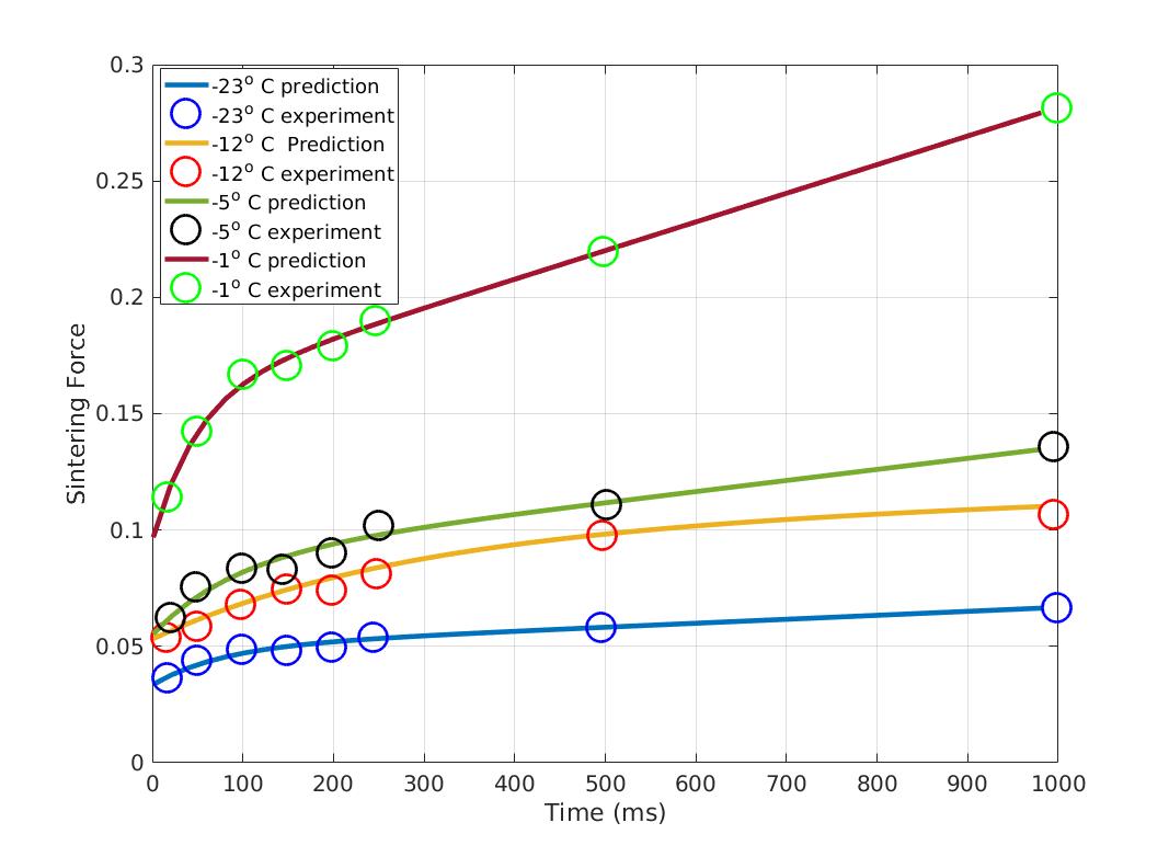
The fast sintering experiment consist of putting two spherical ice particles into contact with a given load for a short time and then applying separation force until fracture of the created bond. The applied load, fracture force and sintering time are then recorded. Szabo and Schneebeli performed such experiment by putting two cones of 3mm radius at the tip into contact for different times [10]. The fracture force also called sintering force vs time can be translated into strain vs time curve or indentation vs time using spherical contact mechanics. If the equivalent radius of the two spheres is and the indentation is known, the bond area can be calculated as follow:
| (42) |
Assuming that the tensile strength is constant under the experimental conditions, the indentation can be related to the fracture force as follow :
| (43) |
| Temperature | |||||
|---|---|---|---|---|---|
| -1 | 0.15385e+03 | 15.698 | 0.30783 | 0.08411 | |
| -5 | 0.39047e+03 | 43.230 | 0.53908 | 0.06535 | |
| -12 | 0.70373e+03 | 81.653 | 0.60423 | 0.05 | |
| -23 | 1.0444e+03 | 82.50 | 1.1561 | 0.0298 |
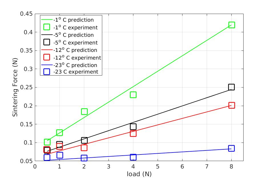
Under these assumptions, the fast sintering data can be exploited as creep data. Linear extrapolation of measured load dependent sintering force agrees with the existence of non null temperature dependent sintering force when no load has been applied. The load independent portion of the fracture force can be included into equation 42 :
| (44) |
In this paper, the four parameters of the Burger’s model and have been obtained by this approach using the damped least-squares (DLS) method. The results of this calibration process are presented in Figure 6 and the parameters are listed in Table 1. The bonds viscoelastic properties are calulated as following :
| (45) | |||
| (46) | |||
| (47) |
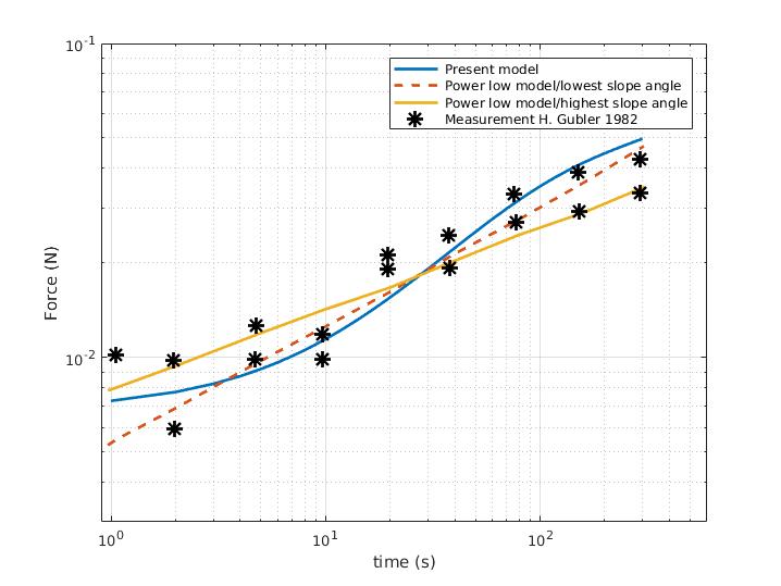
In the present model the growth rate of the bond between the particles is linearly dependent on the pressure at the interface. The pressure dependency is in agreement with the experimental data presented by Szabo and Schneebeli [10]. Figure 7 show results of fracture force vs applied pressure of two particles of radius for a sintering time of 250ms. It is worth mentioning that the rate at which the tensile load have been applied for the bond fracture are supposed to allow no appreciable viscous flow.
Time-temperature superposition can be used to establish the relation between viscosity and temperature. For ice, the Arrhenius relation have been used [19, 44, 45]. The Arrhenius type creep rate relation :
| (48) |
Barnes proposed a model that describes the secondary creep of ice in a temperature range of to and strain rate ranging between and . The activation energy was sugested to be for temperatures above and for temperatures below. Other researchers found much lower values for the activation energy for to [44] and for temperature range of to by [45]. The difference in activation energy is believed to come from some liquid at grain boundaries. Barnes also suggested that by this process the creep rate is supposed to be higher for decreasing grain size. This implies that the creep rate found in individual snow grains are higher than that macroscopic ice leading to even higher macroscopic creep rate of snow. Since densification and grain growth are linked, the creep rate is expected to decrease with increasing density [19, 16]. In this study, the Williams-Landel-Ferry (WLF) model have been used to establish temperature dependency of viscosity constants:
| (49) | |||
| (50) |
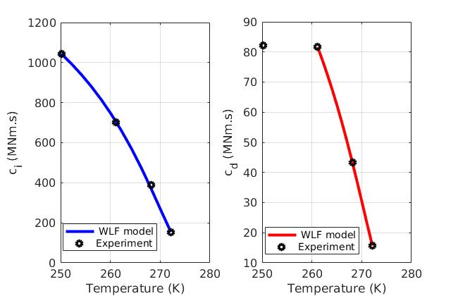
As one can see in figure. 8 the variation of the delayed viscosity is pronounced between and . Below no significant increase is found where as the instantaneous viscosity linked to secondary creep still increase. From the experimental values the following empirical relation have been found:
| (51) | |||
| (52) | |||
| (53) |
The reference temperature was taken to be .
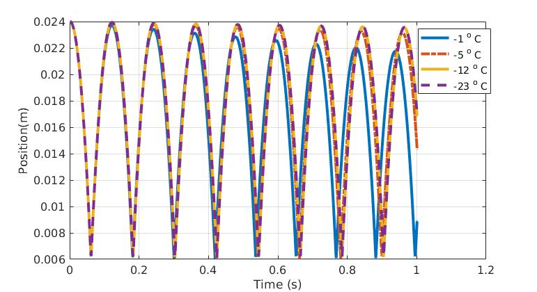
Both viscosity constants and are function of temperature and increase with decreasing temperature. The elasticity constant are assumed to be constant with varying temperature and the values are chosen close to the Young modulus. The figure 9 illustrates the influence of temperature on the apparent restitution coefficient. An ice particle falling on ice surface of same temperature show lower restitution coefficient at higher temperature. Although no significant change is found above . The fast sintering experiment was also performed by Gubler at different temperature [8]. The data extracted from experiments by Szabo and Schneebeli are also in agreement with Gubler’s experiments.
5 Conclusion
A conceptual model has been developed to mimic micromechanisms that take place in snow. The macroscopic behavior is governed by grain bonding, de-bonding leading to crack initiation and propagation and all processes that take place in the crack region. Interactions between ice grains are described using rheological models. Intergranular fracture mechanisms were introduced by the means of quasi-brittle bonds. The model also includes thermo-mechanical description of bond growth. An exponential softening law was used for post-peak behavior of the bonds.
The main features can be summarized as follow:
-
1.
full microstructure is taken in to account for mechanical response;
-
2.
temperature dependent evolution of the microstructure by creep and sintering;
-
3.
size effect in fracture mechanism and rate dependent behavior.
References
References
- [1] Snow Metamorphism: The Force Behind Our Ever-Changing Snowpack, Excerpts from Rock Talk 7 (3).
- [2] S. Cresseri, C. Jommi, Snow as an elastic viscoplastic bonded continuum: a modelling approach, Italian Geotechnical 4 (2005) 43–58.
- [3] E. E. Adams, S. M. Jepsen, B. Close, A bonding process between grains in mechanically disaggregated snow, in: Annals of Glaciology, 2008. doi:10.3189/172756408784700770.
-
[4]
M. Faraday, Note on Regelation,
Proceedings of the Royal Society of London 10 (1859) 440–450.
URL http://www.jstor.org/stable/111669 - [5] U. Nakaya, A. Matsumoto, Simple experiment showing the existence of "liquid water" film on the ice surface, Journal of Colloid Science 9 (1) (1954) 41–49. doi:https://doi.org/10.1016/0095-8522(54)90084-7.
- [6] W. D. Kingery, Regelation, Surface Diffusion, and Ice Sintering, Journal of Applied Physics 31 (1960) 833 – 838. doi:https://doi.org/10.1063/1.1735704.
-
[7]
P. V. Hobbs, B. J. Mason, The
sintering and adhesion of Ice, The Philosophical Magazine: A Journal of
Theoretical Experimental and Applied Physics 9 (98) (1964) 181–197.
doi:10.1080/14786436408229184.
URL https://doi.org/10.1080/14786436408229184 -
[8]
H. Gubler,
Strength
of Bonds between Ice Grains after Short Contact Times, Journal of
Glaciology 28 (100) (1982) 457–473.
doi:10.3189/S0022143000005050.
URL https://www.cambridge.org/core/product/identifier/S0022143000005050/type/journal_article -
[9]
D. Kuroiwa, A Study of Ice
Sintering, Tellus 13 (2) (1961) 252 – 259.
doi:DOI:10.1111/j.2153-3490.1961.tb00082.x.
URL https://doi.org/10.3402/tellusa.v13i2.9450 - [10] D. Szabo, M. Schneebeli, Subsecond sintering of ice, Applied Physics Lettersdoi:10.1063/1.2721391.
-
[11]
W. A. Weyl,
Surface
structure of water and some of its physical and chemical manifestations,
Journal of Colloid Science 6 (5) (1951) 389 – 405.
doi:https://doi.org/10.1016/0095-8522(51)90011-6.
URL http://www.sciencedirect.com/science/article/pii/0095852251900116 - [12] H. H. Jellinek, Liquid-like (transition) layer on ice, Journal of Colloid And Interface Sciencedoi:10.1016/0021-9797(67)90022-7.
-
[13]
N. H. Fletcher, Surface
structure of water and ice, The Philosophical Magazine: A Journal of
Theoretical Experimental and Applied Physics 18 (156) (1968) 1287–1300.
doi:10.1080/14786436808227758.
URL https://doi.org/10.1080/14786436808227758 -
[14]
P. W. Thomson, XII. The
effect of pressure in lowering the freezing-point of water experimentally
demonstrated, The London, Edinburgh, and Dublin Philosophical Magazine and
Journal of Science 37 (248) (1850) 123–127.
doi:10.1080/14786445008646566.
URL https://doi.org/10.1080/14786445008646566 - [15] B. Kabore, B. Peters, C. Willibald, T. Thiele, M. Schneebeli, Multi-scale modelling of snow mechanics, in: 41st Solid Mechanics Conference (SOLMECH 2018), Warsaw, Poland, 2018.
- [16] H. Bader, The physics and mechanics of snow as a material., Tech. rep. (1962).
- [17] K. F. Voitkovskii, The mechanical properties of ice ().
- [18] Homer T. Mantis, REVIEW OF THE PROPERTIES OF SNOW AND ICE.
-
[19]
P. Barnes, D. Tabor, J. C. F. Walker, F. R. S. And,
The
Friction and Creep of Polycrystalline Ice, Source: Proceedings of the Royal
Society of London. Series A, Mathematical and Physical Sciences Proc. Roy.
Soc. Lond. A 324 (324) 127–155.
URL http://www.jstor.org/stable/77933http://about.jstor.org/terms - [20] M. Mellor, A review of basic snow mechanics, in: Snow mechanics Symposium, IAHS-Publication, Grindelwald, 1974, pp. 251 – 291.
- [21] O. Castelnau, P. Duval, M. Montagnat, R. Brenner, Elastoviscoplastic micromechanical modeling of the transient creep of ice, Journal of Geophysical Research: Solid Earthdoi:10.1029/2008JB005751.
-
[22]
P. Duval, Fluage de la glace
polycristalline, Rheologica Acta 13 (3) (1974) 562–566.
doi:10.1007/BF01521756.
URL https://doi.org/10.1007/BF01521756 -
[23]
L. H. Shapiro, J. B. Johnson, M. Sturm, G. L. Blaisdell,
Snow Mechanics Review of the State of
Knowledge and Applications.
URL http://www.dtic.dla.mil/ -
[24]
Z. Yosida, H. Oura, D. Kuroiwa, T. Huzioka, K. Kojima, S.-I. Aoki,
S. Kinoshita, Physical Studies on
Deposited Snow. II. ; Mechanical Properties. (1), Tech. rep., Institute of
Low Temperature Science, Hokkaido University (1956).
URL http://hdl.handle.net/2115/20218 -
[25]
J. Chen, Discrete Element
Method (DEM) Analyses for Hot-Mix Asphalt (HMA) Mixture Compaction
"Discrete Element Method (DEM) Analyses for Hot-Mix Asphalt (HMA)
Mixture Compaction, Ph.D. thesis, University of Tennessee, Knoxville
(2011).
URL http://trace.tennessee.edu/utk_graddiss/957 - [26] M. Di Paola, R. Heuer, A. Pirrotta, Fractional visco-elastic Euler-Bernoulli beam, International Journal of Solids and Structuresdoi:10.1016/j.ijsolstr.2013.06.010.
- [27] G. E. H. Ballard, E. D. Feldt, A THEORETICAL CONSIDERATION OF THE STRENGTH OF SNOW, Journal of Glaciology 6 (43) (1966) 159–170. doi:DOI:10.1017/S0022143000019146.
- [28] H. Kim, M. P. Wagoner, W. G. Buttlar, Simulation of Fracture Behavior in Asphalt Concrete Using a Heterogeneous Cohesive Zone Discrete Element Model, Journal of Materials in Civil Engineeringdoi:10.1061/(ASCE)0899-1561(2008)20:8(552).
- [29] H. Kim, W. G. Buttlar, Discrete fracture modeling of asphalt concrete, International Journal of Solids and Structuresdoi:10.1016/j.ijsolstr.2009.02.006.
- [30] A. Tarokh, A. Fakhimi, Discrete element simulation of the effect of particle size on the size of fracture process zone in quasi-brittle materials, Computers and Geotechnicsdoi:10.1016/j.compgeo.2014.07.002.
- [31] M. Galouei, A. Fakhimi, Size effect, material ductility and shape of fracture process zone in quasi-brittle materials, Computers and Geotechnicsdoi:10.1016/j.compgeo.2014.12.010.
- [32] J. Liu, J. Sarout, M. Zhang, J. Dautriat, E. Veveakis, K. Regenauer-Lieb, Computational upscaling of Drucker-Prager plasticity from micro-CT images of synthetic porous rock, Geophysical Journal Internationaldoi:10.1093/gji/ggx409.
- [33] E. M. Schulson, The fracture of water ice Ih: A short overview, Meteoritics & Planetary Sciencedoi:10.1111/j.1945-5100.2006.tb00432.x.
- [34] E. M. Schulson, Brittle failure of ice, Engineering Fracture Mechanics 68 (17-18) (2001) 1839–1887. doi:https://doi.org/10.1016/S0013-7944(01)00037-6.
-
[35]
E. M. Schulson, P. Duval,
Brittle
compressive failure of confined ice, in: Creep and Fracture of Ice,
Cambridge University Press, Cambridge, 2009, pp. 266–319.
doi:10.1017/CBO9780511581397.013.
URL https://www.cambridge.org/core/product/identifier/CBO9780511581397A096/type/book_part - [36] E. M. Schulson, THE FRACTURE OF ICE Ih, JOURNAL DE PHYSIQUEdoi:10.1051/jphyscol:1987129.
- [37] D. O. Potyondy, P. A. Cundall, A bonded-particle model for rock (2004). doi:10.1016/j.ijrmms.2004.09.011.
-
[38]
F. P. Bowden, Friction on Snow and
Ice, Source: Proceedings of the Royal Society of London. Series A
Mathematical and Physical Sciences 217 (1131) (1953) 462–478.
URL http://www.jstor.org/stable/99062 - [39] S. Sukhorukov, S. Løset, Friction of sea ice on sea ice, Cold Regions Science and Technologydoi:10.1016/j.coldregions.2013.06.005.
- [40] K. Iwashita, M. Oda, ROLLING RESISTANCE AT CONTACTS IN SIMULATION OF SHEAR BAND DEVELOPMENT BY DEM, Journal of Engineering Mechanics 124 (3).
- [41] S. Luding, Introduction to discrete element methods: Basic of contact force models and how to perform the micro-macro transition to continuum theory, European Journal of Environmental and Civil Engineering 12 (7-8) (2008) 785–826. doi:10.1080/19648189.2008.9693050.
- [42] C. W. Gear, The numerical integration of ordinary differential equations, Mathematics of Computationdoi:10.1090/S0025-5718-1967-0225494-5.
-
[43]
K. SAMIEI, Assessment of implicit and
explicit algorithms in numerical simulation of granular matter, Ph.D.
thesis, University of Luxembourg (2012).
URL http://hdl.handle.net/10993/15668 - [44] M. A. Rist, S. A. F. Murrell, Ice triaxial deforntation and fracture, Journal of Glaciology 40 (135).
- [45] R. E. GAGNON, P. H. GAMMON, Triaxial experinlents on iceberg and glacier ice 4 (139).