Radiation pressure in finite Fabry-Pérot cavities
Abstract
We study the effect of finite size and misalignment on a fundamental optomechanical setup: a Fabry-Pérot cavity with one fixed and one moveable mirror. We describe in detail light confinement under these real world imperfections and compare the behaviour of the intracavity and output fields to the well-known ideal case. In particular, we show that it is possible to trace the motion of the movable mirror itself by measuring intensity changes in the output field even in the presence of fabrication shortcomings and thermal noise. Our result might be relevant to the transition from high precision research experiments to everyday commercial applications of optomechanics; such as high-precission stepmotor or actuator positioning.
I Introduction
Optomechanics (OM) studies the interaction of an electromagnetic radiation field with a mechanical oscillator. The dynamics of each subsystem, well-described within the classical and quantum frameworks, become non-linearly coupled, revealing a plethora of new fundamental effects as well as applications Milburn and Woolley (2011); Meystre (2013); Aspelmeyer et al. (2014); Bowen and Milburn (2016). OM systems range from macroscopic mirrors used to detect gravitational waves Chaibi and Bondu (2011); Miao et al. (2015) to microscopic cantileversGigan et al. (2006); Arcizet et al. (2006); Kleckner and Bouwmeester (2006) and membranes Thompson et al. (2008) used in the search for macroscopic quantum state engineering. Applying a well-defined driving field, the state of the mechanical oscillator can be prepared, and then coherently controlled Fabre et al. (1994); Mancini and Tombesi (1994); Aldana et al. (2013). This allows, for example, to either cool the mechanical motion or amplify the forces acting on it solely by manipulating the electromagnetic field Metzger et al. (2008). This is the basis for all kinds of high-precision measurements or quantum information processes.
Radiation pressure is the origin behind optomechanical coupling Lebedev (1901); Nichols and Hull (1901). The first experimental proof of such an effect dates back to 1967 Braginsky and Manukin (1967), while the interaction between visible light and a macroscopic mechanical oscillator was demonstrated in 1983 Dorsel et al. (1983). Law provided the first consistent second quantization of the model in 1995 Law (1995), showing that the cavity frequency change leads, in general, to a complex coupling between creation and annihilation operators of the optical and mechanical subsystems. This coupling is usually restricted to the linear regime in quantum OM due to the limited amplitude of the mechanical oscillation Schliesser and Kippenberg (2010). However, recently technical developments has put the nonlinear range of interaction within reach and jump-started research into corrections to the standard OM description Sala and Tufarelli (2018).
We focus on a resonator that is finite in size and possible misalignment of the incident beam. These imperfections deterministically limit the confinement time of the field inside the resonator. This is an ever-present issue that state-of-the-art laboratories can suppress as much as possible for high-end technology applications. In contrast, our motivation sparks from the potential application of these systems in everyday, mass-produced applications where an adequate characterization of imperfections might be crucial for their use. Our setup is a driven high-finesse Fabry-Perot (FP) resonator made from two plane, highly-reflecting mirrors Born and Wolf (1980). We consider the classical optical response function of the cavity Dorsel et al. (1983); Gozzini et al. (1985); Ujihara and Meystre (1985) driven by a monochromatic laser. Radiation pressure produces a displacement of the movable mirror that, in turn, leads to a change in the phase that the intracavity field accumulates and, in the end, modifies the sensitivity of the interferometer. In general, there is a trade-off between that sensitivity and the broadness of the FP radiation pressure (FPRP) resonance for varying the reflectivities of the mirrors. This trade-off is measurable in the output field in front of the fixed mirror. In this case, however, we show that the effect of the reflectivity of the mirrors on the output intensity is suppressed, allowing a stable measurement.
In the following, we review the results for an ideal cavity for the sake of comparison. Then, we incorporate the effect of finite cavity size and input beam misalignment to show that the intracavity response function for limited confinement time is just the ideal one times a fast oscillating factor controlled by the number of intracavity reflections. We also discuss the effect of limited mirror reflectivity; it causes further broadening and scaling-down of the FPRP resonance around its maximum value but the phase sensitivity and the output field behaviour is mostly preserved. Afterwards, we analyse how these finite size effects would reflect on precision measurements including thermal mechanical noise. Finally, we provide some conclusions and an outlook.
II Ideal Fabry-Pérot Cavity Review
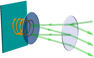
Let us first recap the well-known results for the radiation-pressure-induced response of the optomechanical system depicted in Fig. 1 Sala and Tufarelli (2018). A cavity made of two highly-reflective mirrors, one allowed to undergo harmonic motion and the other fixed, separated by a distance can be excited to a certain resonance, with the number of the excited harmonic and the angle between the normal of the cavity walls and the direction of the incident driving monochromatic laser of frequency Gong et al. (2009). Radiation pressure arises from momentum transfer of the light field to the moving mirror and is proportional to the Poynting vector , with the total electric field impinging on the moveable mirror. We assume the transverse area of the laser constant as the laser travels through the cavity. The total field amplitude can be given in terms of the response function that relates it with respect to the driving laser intensity . For an infinitely long cavity, we can calculate the transfer function,
| (1) |
in terms of the ideal maximum response,
| (2) |
obtained at the half-round trip phase , the Airy function, and the coefficient of finesse Born and Wolf (1980),
| (3) |
in that order. Here the reflectivities of the moveable and fixed mirrors are given by the parameters and , respectively. The half-round trip phase gained by the field inside the cavity,
| (4) |
is proportional to the fixed resonator half-round trip phase and the position of the moveable mirror .
We find it useful to consider two particular cases of mirror configurations: (I) one where the mirrors are identical, , and (II) another where the moveable mirror is ideal, . In the first case, we find that the response function changes from to approximately . In the second, it changes from to . For a high reflectivity of , this means a change of for case (I) and for case (II). Such an enormous change in the response function leads to the question of phase sensitivity. The phase that provides us with will be denoted and is given by
| (5) |
At this point the response of the resonator becomes as small as if the laser light would directly impinge just once on the moveable mirror. For our two cases, this phase reduces to
| (6) |
and we find for a reflectivity value of . We see that even the tiniest deviation from resonance drastically diminishes the effect of FPRP. For both cases, if the following condition holds,
| (7) |
there is no real solution for , as for all values of . It is thus paramount to have the reflectivity of the moveable mirror at least as large as, if not significantly larger than, the reflectivity of the fixed mirror.
Here, we can take a stop and make two assumptions: (i) the driving laser is dominant, thus the field quadratures follow only this laser oscillation in the long-time limit, and (ii) the position of the moveable mirror can be approximated by a constant in the long-time limit, , due to the absence of direct driving and the presence of damping. This steady state can either be numerically evaluated from the balance of forces, or measured indirectly. These assumptions yield for the long-time limit of the half-round trip phase
| (8) |
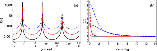
The driving laser and cavity field pressure contributions provide only positive moveable mirror displacements, , for all cases. Thus, we are required to set the laser below the bare resonance, , in order to reach the maximum of the response function, , in the long-time limit. The response functions for three different reflectivities in case (II) are depicted in Fig. 2(a). It is clear that there is a tradeoff between a large intensity jump in the response function, and its phase broadness around . That means that for high reflectivities, small amounts of shift of the moveable mirror may lead to big variations in the response function. Let us reconsider Eq. (6) for case (II) and express the phase shift from FPRP resonance in terms of the cavity wavelength corresponding to . We find
| (9) |
For the laser being on bare cavity resonance and almost in normal incidence (), the mirror shift compared to the wavelength is just . For a high reflectivity a phase-shift to thus corresponds to a movement of . For a He-Ne-laser driven cavity this equals 1.6 nm. Within a movement of the mirror of 1.6 nm, the response function changes by a factor of 4000. That is, if we can experimenteally determine this quantity we would be extremely sensitive in a very small region. On the other hand, for and case (II), the response changes only by a factor of roughly 38, but this change occurs over a range of or 16 nm.
The actual displacement of the moveable mirror is generally hard to measure. Thus, we analyze the output intensity , transmitted back through the fixed mirror, instead. Making a similar calculation as for the field hitting the moveable mirror we obtain
| (10) |
The first term on the right-hand side of Eq. (10), , stems from the initial reflection when entering the cavity. The left-hand side would just be this without a second mirror, , implying that a deviation from that value is fully based on the constructive interference displayed by the response function. Both cases (I) and (II) for different reflectivities are depicted in Fig. 2(b).
The maximum value, given for FPRP resonance in both cases, can be shown to be
| (11) |
for case (I) and
| (12) |
for case (II). In contrast to the response function this maximum is little effected by variations of , making this maximum resistent to the actual mirror parameters. For large reflectivities the phase dependence of the output field mimics the behaviour of the reflected field, just for a smaller parameter region. Thus, we only see a sharp peak around , whereas for all other phases the intensity is almost constant. If the reflictivities go down on the other hand, we again see this tradeoff between lower intensity change and broader range of phase deviations for which this change occurs. That means higher reflectivities should allow an extremely sensitive measurement of the mirror movement, but only for a very small range of movements. On the other hand lower reflectivities are less sensitive, but on a broader range.
Quantitatively we can use the results for the response function again, because, one can easily show that
| (13) |
for case (I) and
| (14) |
for case (II). In other words, in case (I) and for large reflectivity , the output intensity changes from to when the moveable mirror position changes by % of the cavity wavelength.
III Finite Size effects
The finite length of planar mirror walls implies that light at non-normal incidence, , will only stay a limited amount of time inside the cavity, independent of the reflectivities. In this case, the geometric series at the heart of the response function becomes limited, yielding just a scaled version of the ideal response function,
| (15) |
where is the number of hits on the back mirror. This number can be calculated from the system geometry or recovered from the maximum of the finite response function at for non-ideal reflectivitys ,
| (16) |
In this approximation, we used the restrictions and . For example, for , we need 32 bounces to obtain , which yields a mirror size of at least for the fundamental mode . This means mirrors must be at least in size for He-Ne laser light, , at incident angle without considering the obvious diffraction issues.
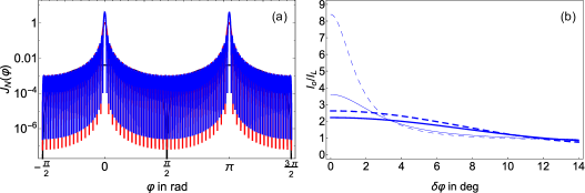
The maxima of are broader and have lower values than the ideal case of , and slowly approach the ideal response with increasing . Figure 3 shows the finite response function for the cases of non-normal incidence allowing for bounces in solid black, where the FPRP on resonance is still smaller than if the laser light would impinge directly on the moveable mirror just once. The case delivering a maximum unit finite response of one, bounces on the moveable mirror, is shown in dashed blue and the response for double that number, , is shown in dotted red lines yielding a maximum response slightly below to a value of four. The influence of the FPRP is quite fragile towards the geometry of the resonator, in particular mirror size related to incident angle and the ratio between the driving laser and the long-time cavity frequencies.
A similar but lengthy formula as Eq. (10) can be derived for the output field of a finite mirror and . The dependence of the output field in this case is shown in Fig. 3(b). In this case, we consider the low reflectivity of and only hits on the back mirror. The maximum amplitude at does not yet approach its ideal value, thus limiting the sensitivity in that range. However, in a medium range of phases, the intensity is even higher for low than for the infinite case. In other words, while a precise determination of the phase and thus the mirror displacement is practically impossible, it is far easier to obtain a rough estimation over a broader range of phases.
We can conclude a few things. First, the relation between input and output field at the fixed mirror is connected to the same response function as the reflection field at the moveable mirror. Second, the output field is limited to values below nine times the driving laser intensity and this maximum is less sensitive to the actual reflectivities than the response function. Third, for high reflectivities a very small range of phase changes, i.e. movements of the mirror, can be sensitively detected by comparing the output intensity with the laser intensity. In contrast, for lower reflectivity, a broader range of phases yields a less varying output intensity. There is a general tradeoff between the range of mirror movements that yield a variation of the output intensity and the amplitude of this variation, which we called the sensitivity. If the variation is detectable, it allows a one-to-one relation between the movement of the mirror and . Fourth, when only a finite amount of mirror reflections is considered, the tradeoff above appears to favor a broader range while the sensitivity decreases. Additionally, for case (II), we find oscillations appearing at larger , leading to unwanted ambiguities in the determination of .
IV Application Outlook
In order to better motivate the idea that finite size effects do not destroy the applicability of these systems for precision measurements, let us consider a measurement scenario under thermal mechanical noise. We focus on a description via the equipartition theorem Landau and Lifshitz (1980) but we note that there are other approaches to threat noise sources, for example based on the fluctuation dissipation theorem Callen and Greene (1952); Liu et al. (2012), which we do not discuss here. Following the standard description of a classical mechanical damped harmonic oscillator with mass , frequency , damping rate , and temperature , we can calculate the average thermal motion as
| (17) |
with the Boltzmann constant . The range of optomechanical devices and, thus, parameters for a moveable mirror is vast, so let us consider the question of mechanical noise more generally. The output field phase is changed by the mirror movement as . The latter value is fixed for a given setup and temperature. It becomes clear that the general requirement for high precision measurement should not be larger than a fraction of a degree. However, due to the phase prefactor , this implies that the displacement-to-length ratio must fulfill . For higher precision we must preferably aim for .
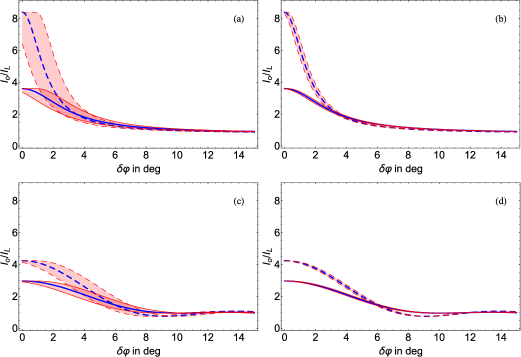
Figure 4 depicts the effect of thermal mechanical noise on the output field intensity, normalized by the driving laser intensity, for displacement-to-length ratios of , Fig. 4(a) and Fig. 4(c), as well as , Fig. 4(b) and Fig. 4(d). The larger the noise, the worse the sensitivity to phase changes in the output field intensity for both ideal, Fig. 4(a) and Fig. 4(b), and finite cavities, Fig. 4(c) and Fig. 4(d). The lower value of the mechanical noise is almost invisible. Unfortunatetly, oscillations in the output field set in for the finite case, Fig. 4(c) and Fig. 4(d), leading to an ambiguity above in the depicted examples. Roughly speaking, one generally requires a displacement-to-length ratio for low noise. At room temperature, K, this value is restricted by the condition
| (18) |
where the parameter is the effective spring constant of the movable mirror. As an example, let us consider the microelectromechanical-system cantilever with an effective spring constant 0.17 N/m from Ref. Liu et al. (2004). For optical driving with an He-Ne laser and a cavity with length nm, we obtain keV, which is four times as high as our lower bound. Taking into account the progress since this work our requirements should be easily realizable in everyday production.
Now, let us think about a setup where the fixed mirror is movable via a linear actuator or step motor. These are used to automate tiny movements in larger structures. Modern step motors allow a controlled periodic increment of motion by around 5 nm, not accounting for friction limitations Ste (2018). Depending on the intensity sensitivity of our detector, we can easily reach that resolution with reflectivities of in setup (II), as the range in which strong phase sensitivity occurs is roughly 16 nm. Keep in mind that this is not the resolution limit, just the range in which the system is very sensitive.
Let us assume again the cantilever from Liu et al. (2004), as well as the He-Ne-laser and cavity length approximately at half the laser wavelength. Moreover, we fix the number of impinges at . In this setup most of the ambiguities due to oscillation have died down allowing an unambiguous relation between field intensity and mirror motion on one side of the FPRP resonance. If we set exactly at half the laser wavelength, the system would be at resonance without any external laser driving. For roughly 100 mW laser power, the equilibrium point would move to the middle of the first downward slope, allowing strong phase sensitivity. Increasing the laser power further to around 200 mW, we reach the less steep region, in which a broader range of phases are covered with less change of the output intensity. If the unperturbed cavity length is slightly off from resonance, this can also be corrected by increasing or decreasing the laser power correspondingly. Hence, only by controlling the intensity of the driving laser we can move in or out of resonance to a point in the response function where sensitivity is lower but broader in phase change, or vice versa. We might include such an optomechanical setup in linear actuators to switch between finder, low-precision/high-range, and measuring, high-precision/low-range, set-ups with the same device just modifying the driving laser intensity even in the presence of mechanical noise.
V Conclusions
We studied the influence of finite size and misalignment on an optomechanical cavity setup with one moveable mirror. Radiation pressure pushes the cavity walls apart and creates a well-known phase-sensitive response of the intracavity field. For non-normal incidence of laser light, it can only impinge on the mirrors a limited number of times before leaving the cavity, independent of the mirror reflectivity. We incorporate the effects of these imperfections into the well-known dynamics of the ideal cavity setup. For highly-reflecting mirrors the evolving extreme sensitivity in a very narrow region around the resonance of the maximal response function implies that tiniest movements of the mirror yield strong variations of the field amplitude. For lower reflectivities, this sensitivity decreases but, in exchange, the phase range of the resonance increases. As a measurable quantity, we calculated the output field in front of the fixed mirror. While displaying the same sensitivity-range trade-off for measuring the phase-shift, the range of output intensities is much smaller and little affected by the actual reflectivities. Hence, similar to the response function, we can have extreme sensitivity in a very small range of mirror displacements (sub-percent of the cavity wavelength) or reasonable sensitivity in a broader range. For limited resonances and a medium number of reflections, the range of phases covered by the resonance may be even broader than for an infinite cavity. We calculated the thermal mechanical noise in such a setup to motivate using the output field to measure mirror displacements even in far-from-ideal conditions. Thermal noise appears to have a small effect for reasonable microscopic mirrors setups.
Acknowledgements.
B.M.R.L acknowledges funding from Consejo Nacional de Ciencia y Tecnología (CONACYT) (CB-2015-01-255230) and thanks Cinthia Huerta Alderete for her help with Fig. 1.References
- Milburn and Woolley (2011) G.J. Milburn and M.J. Woolley, “An introduction to quantum optomechanics,” Acta Phys. Slovaca 61, 483 (2011).
- Meystre (2013) P. Meystre, “A short walk through quantum optomechanics,” Ann. Phys. (Berlin) 525, 215 (2013), arXiv:1210.3619 [quant-ph] .
- Aspelmeyer et al. (2014) M. Aspelmeyer, T. J. Kippenberg, and F. Marquardt, “Cavity optomechanics,” Rev. Mod. Phys. 86, 1391–1452 (2014), arXiv:1303.0733 [cond-mat.mess-hall] .
- Bowen and Milburn (2016) W.P. Bowen and G.J. Milburn, Quantum Optomechanics (CRC Press, 2016).
- Chaibi and Bondu (2011) W. Chaibi and F. Bondu, “Optomechanical issues in the gravitational wave detector Advanced VIRGO,” C. R. Physique 12, 888 (2011).
- Miao et al. (2015) H. Miao, Y. Ma, C. Zhao, and Y. Chen, “Enhancing the Bandwidth of Gravitational-Wave Detectors with Unstable Optomechanical Filters,” Phys. Rev. Lett. 115, 211104 (2015), arXiv:1506.00117 [quant-ph] .
- Gigan et al. (2006) S. Gigan, H. R. Böhm, M. Paternostro, F. Blaser, G. Langer, J. B. Hertzberg, K. C. Schwab, D. Bäuerle, M. Aspelmeyer, and A. Zeilinger, “Self-cooling of a micromirror by radiation pressure,” Nature 444, 67 (2006), arXiv:quant-ph/0607068 .
- Arcizet et al. (2006) O. Arcizet, P.-F. Cohadon, T. Briant, M. Pinard, and A. Heidmann, “Radiation-pressure cooling and optomechanical instability of a micromirror,” Nature 444, 71 (2006), arXiv:quant-ph/0607205 .
- Kleckner and Bouwmeester (2006) D. Kleckner and D. Bouwmeester, “Sub-kelvin optical cooling of a micromechanical resonator,” Nature 444, 75 (2006).
- Thompson et al. (2008) J. D. Thompson, B. M. Zwickl, A. M. Jayich, F. Marquardt, S. M. Girvin, and J. G. E. Harris, “Strong dispersive coupling of a high-finesse cavity to a micromechanical membrane,” Nature 452, 72 (2008), arXiv:0707.1724 [quant-ph] .
- Fabre et al. (1994) C. Fabre, M. Pinard, S. Bourzeix, A. Heidmann, E. Giacobino, and S. Reynaud, “Quantum-noise reduction using a cavity with a movable mirror,” Phys. Rev. A 49, 1337 (1994).
- Mancini and Tombesi (1994) S. Mancini and P. Tombesi, “Quantum noise reduction by radiation pressure,” Phys. Rev. A 49, 4055 (1994).
- Aldana et al. (2013) S. Aldana, C. Bruder, and A. Nunnenkamp, “Equivalence between an optomechanical system and a Kerr medium,” Phys. Rev. A 88, 043826 (2013), arXiv:1306.0415 [quant-ph] .
- Metzger et al. (2008) C. Metzger, M. Ludwig, C. Neuenhahn, A. Ortlieb, I. Favero, K. Karrai, and F. Marquardt, “Self-Induced Oscillations in an Optomechanical system driven by Bolometric Backaction,” Phys. Rev. Lett. 101, 133903 (2008).
- Lebedev (1901) P. Lebedev, “Untersuchungen über die Druckkräfte des Lichtes,” Ann. Phys. 6, 433 (1901).
- Nichols and Hull (1901) E. F. Nichols and G. F. Hull, “A Preliminary Communication on the Pressure of Heat and Light Radiation,” Phys. Rev. 13, 307 (1901).
- Braginsky and Manukin (1967) V. B. Braginsky and A. Manukin, “Ponderomotive Effects of Electromagnetic Radiation,” Sov. Phys. JETP 25, 653 (1967).
- Dorsel et al. (1983) A. Dorsel, J. D. McCullen, P. Meystre, E. Vignes, and H. Walther, “Optical Bistability and Mirror Confinement Induced by Radiation Pressure,” Phys. Rev. Lett. 51, 1550 (1983).
- Law (1995) Law, “Interaction between a moving mirror and radiation pressure: A Hamiltonian formulation,” Phys. Rev. A 51, 2537 (1995).
- Schliesser and Kippenberg (2010) A. Schliesser and T. J. Kippenberg, “Chapter 5 - Cavity Optomechanics with Whispering-Gallery Mode Optical Micro-Resonators,” in Advances In Atomic, Molecular, and Optical Physics, Advances In Atomic, Molecular, and Optical Physics, Vol. 58, edited by Paul Berman, Ennio Arimondo, and Chun Lin (Academic Press, 2010) pp. 207 – 323, arXiv:1003.5922 [quant-ph] .
- Sala and Tufarelli (2018) K. Sala and T. Tufarelli, “Exploring corrections to the Optomechanical Hamiltonian,” Sci. Rep. 8, 9157 (2018), arXiv:1711.06688 [quant-ph] .
- Born and Wolf (1980) M. Born and E. Wolf, Principles of Optics (Pergamon Press, 1980).
- Gozzini et al. (1985) A. Gozzini, F. Maccarrone, F. Mango, I. Longo, and S. Barbarino, “Light-pressure bistability at microwave frequencies,” J. Opt. Soc. Am. B 2, 1841 (1985).
- Ujihara and Meystre (1985) K. Ujihara and P. Meystre, “On the finesse of a phase-conjugate Fabry-Perot resonator using nearly-degenerate four-wave mixing,” Optics Communications 53, 48 (1985).
- Gong et al. (2009) Z. R. Gong, H. Ian, Y. Liu, C. P. Sun, and F. Nori, “Effective Hamiltonian approach to the Kerr nonlinearity in an optomechanical system,” Phys. Rev. A 80, 065801 (2009), arXiv:0805.4102 [quant-ph] .
- Landau and Lifshitz (1980) L.D. Landau and E.M. Lifshitz, Statistical Physics, Part 1 (3rd ed.) (Pergamon Press, 1980).
- Callen and Greene (1952) H. B. Callen and R. F. Greene, “On a Theorem of Irreversible Thermodynamics,” Physical Review 86 (1952).
- Liu et al. (2012) Y. Liu, H. Miao, V. Aksyuk, and K. Srinivasan, “Wide cantilever stiffness range cavity optomechanical sensors for atomic force microscopy,” Opt. Express 20, 18268 (2012), arXiv:1205.3215 [physics.optics] .
- Liu et al. (2004) S Liu, A Davidson, and Q Lin, “Simulation studies on nonlinear dynamics and chaos in a mems cantilever control system,” Journal of Micromechanics and Microengineering 14, 1064 (2004).
- Ste (2018) Example for a state-of-the art step motor: C-663 Mercury, Physik Instrumente (PI) GmbH & Co. KG (2018).