Kirigami mechanics as stress relief by elastic charges
Abstract
We develop a geometric approach to understand the mechanics of perforated thin elastic sheets, using the method of strain-dependent image elastic charges. This technique recognizes the buckling response of a hole under external load as a geometrically tuned mechanism of stress relief. We use a diagonally pulled square paper frame as a model system to quantitatively test and validate our approach. Specifically, we compare nonlinear force-extension curves and global displacement fields in theory and experiment. We find a strong softening of the force response accompanied by curvature localization at the inner corners of the buckled frame. Counterintuitively, though in complete agreement with our theory, for a range of intermediate hole sizes, wider frames are found to buckle more easily than narrower ones. Upon extending these ideas to many holes, we demonstrate that interacting elastic image charges can provide a useful kirigami design principle to selectively relax stresses in elastic materials.
Kirigami, the art of cutting and folding paper has emerged as a powerful tool to dramatically modify, reconfigure and program material properties Mullin et al. (2007); Bertoldi et al. (2010); Florijn et al. (2014); Song et al. (2015); Zhang et al. (2015); Lamoureux et al. (2015); Shyu et al. (2015); Wu et al. (2016); Dias et al. (2017); Rafsanjani and Bertoldi (2017). Since kirigami is scale invariant, it can be combined with rapid miniaturization to design metamaterial response and structures at the smallest scales Rogers and Huang (2009); Deng and Berry (2016). Such approaches were recently demonstrated in graphene Blees et al. (2015) and now provide unprecendented opportunities for designing devices with novel electronic and mechanical properties. With the advent of such technologies, it has become increasingly important to characterize and understand the various ways in which material deformations accomodate stress and stress relaxation through instabilities in thin two dimensional () elastic sheets Eran et al. (2004); Genzer and Groenewold (2006); Witten (2007); Li et al. (2012); Reis et al. (2015); Bertoldi et al. (2017); Dias et al. (2017).
| Configuration | Aspect ratio | |
|---|---|---|
| Planar | – | |
| Buckled \ldelim{33mm | ||
The mechanics of thin elastic sheets is controlled by the dimensionless Föppl-von Kármán (FvK) number Landau and Lifshitz (1986) that indicates the relative ease of in-plane stretching versus out-of-plane bending. Here is a characteristic linear dimension of the sheet, the Young’s modulus and the bending rigidity. Under external load, a thin sheet trades energetically expensive stretching with bending to relieve stresses by either buckling Landau and Lifshitz (1986) or wrinkling Cerda et al. (2002); Cerda and Mahadevan (2003); King et al. (2012), possibly followed by secondary instabilities Ben Amar and Pomeau (1997); Pocivavsek et al. (2008); Witten (2007). By introducing holes or cuts, kirigami now provides a distinct route to locally relieve stresses through these geometric features, though a general characterization of its effective mechanical response is not known. The inverse problem of predicting the correct kirigami pattern to relax a given pre-stress in a material also remains an open problem, complicated by the notorious nonlinearity inherent in thin sheet elasticity.
In this paper, we develop a geometric framework to address some of the general mechanical consequences of kirigami and report on experimental measurements of force-extension curves of pulled paper frames. A more detailed theoretical and numerical analysis is presented in a longer companion paper Moshe et al. (2018). Starting with a single square frame, we use the technique of strain-dependent image elastic charges to show that a hole under external load acts as a geometrically tunable source of local stress, which is relaxed by local buckling. The lowest order image elastic charge induced in a hole is a quadrupolar singularity in Gaussian curvature. When permitted by the shape of the hole, this singularity can fractionalize into partial disclinations, naturally explaining the curvature localization at interior corners seen experimentally for square frames. Thus, the buckling response of the sheet can be viewed as the sheet screening the image charges by adopting a curved configuration that leads to a softer force response. Through a quantitative comparison between theory and experiment, we confirm predictions for the geometric dependence of effective spring constants (summarized in Table 1) and the buckling threshold, along with more local measures of deformation like the full displacement field.
Similar buckling induced softened mechanical response has been previously investigated in periodic arrays of slits under uniaxial tension Shyu et al. (2015); Isobe and Okumura (2016); Rafsanjani and Bertoldi (2017). Our framework rationalizes these previous results, extends to arbitrary hole shapes 111Much of our focus is on square holes, because the concentration of elastic charges at sharp corners simplifies the analysis; elastic charges are delocalized around the rim when one considers, say, circular holes instead., and provides a systematic approach to handle many holes. In addition, collective effects arising from interactions between holes are neglected in works that just analyze the unit cell of a periodic lattice, but are easily captured using the elastic charge framework. Using a flattened cone as an example, we demonstrate how interactions between image charges can guide the design of appropriate kirigami patterns to relax the pre-existing stress in the system.
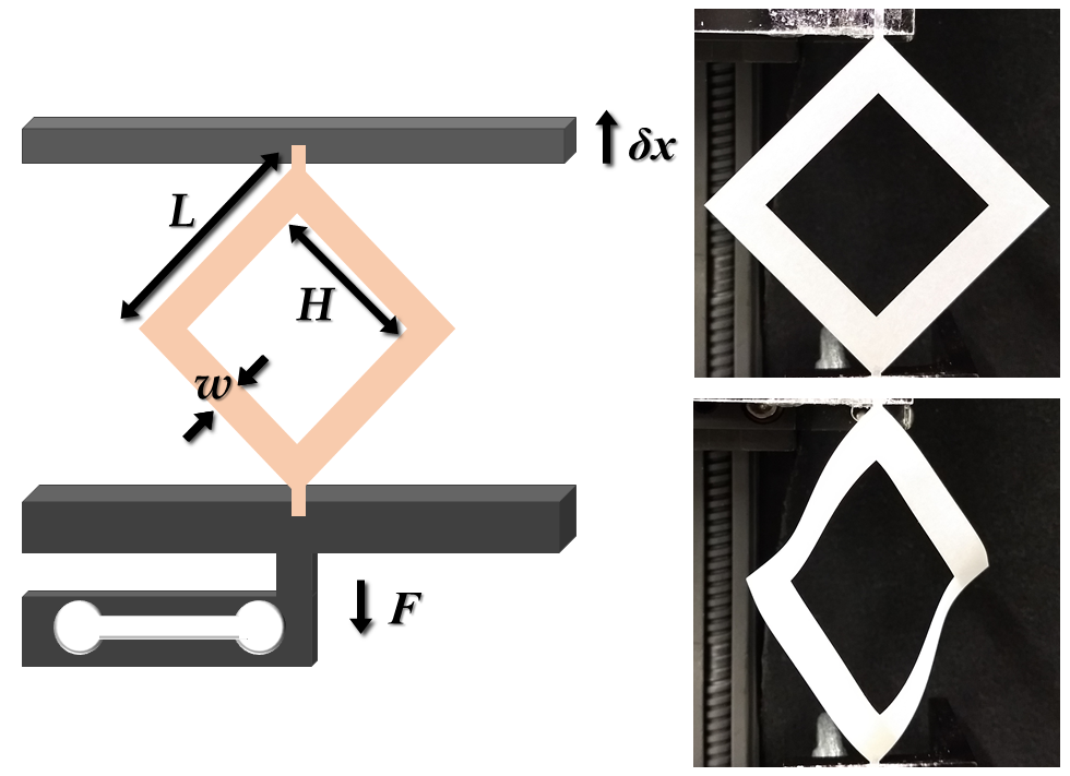
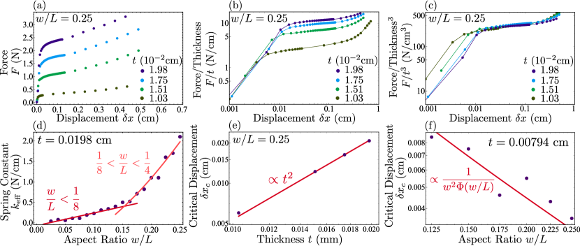
The square frames we study were cut from sheets of Glama Natural paper of various thicknesses ( mm) with an edge length cm. The aspect ratio , where is the frame width and is the hole size (see Fig. 1), was varied between . Frames with larger aspect ratios corresponding to smaller holes often failed before buckling. To measure force-extension curves, we mount the opposite outer corners of the frames between a top and bottom plate and extend them by a distance (fig. 1). To generate displacements we use a rail guided Haydon-Kerk stepper motor to move a micrometer translation stage to which one corner of the frame is attached. Coarse displacements (m) are generated with the stepper motor while finer displacements (m), primarily near buckling, are generated using the micrometer stage. Force measurements were made using a Loadstar parallel cantilever loadcell attached to the bottom plate. Further details of the experimental protocol are given in the SI. We observe a steep increase in force at low displacements, followed by a leveling off beyond a critical displacement, and finally an increase at high displacements just before the frames tear (Fig. 2a).
The initial buckling can be understood within the framework of a stretching to bending transition. The mechanics of the frame is governed by an elastic energy involving both stretching and bending terms quadratic in the stress tensor () and the curvature tensor (). Upon minimizing, we obtain the covariant Föppl-von Kármán (FvK) equations Koiter (1966); Ciarlet (1997),
| (1a) | ||||
| (1b) | ||||
Here we have used the Airy stress function () and the extrinsic curvature tensor is defined by , where and are the local normal and tangent vectors to the surface, and whose determinant gives the Gaussian curvature of the surface. In terms of a Young’s modulus , we have and , where is the sheet thickness and is the three dimensional Poisson ratio Audoly and Pomeau (2010). Unlike the conventional FvK equations for thin plates, we have additionally included a source of Gaussian curvature that plays the same role that defects play in crystals Nelson (2002), though in our case this function describes a distribution of image elastic charges that are induced within the hole and depend on the external load, serving to enforce the appropriate boundary conditions required by the presence of the hole Moshe et al. (2018). Here the analogy with electrostatics helps, in that the hole under external stress functions like a conductive shell in an external electric field. This framework allows for understanding the various scalings observed in the data.
For very small diagonal displacements (, with the buckling threshold), it is clear that the frame responds linearly by stretching (Fig. 2b). Though the frame is still planar, the effective spring constant is modified by the hole geometry. Setting (), we only have , the image elastic charge, present within the hole. Unlike genuine topological disclinations or dislocations (monopole and dipole singularities) that cannot be created by any local deformation Kupferman et al. (2013), the leading order contribution to is a quadrupolar form Moshe et al. (2015a). In the quadrupole can be written as , being its orientation and its magnitude. In the presence of sharp corners in the hole geometry the induced image elastic charge can fractionalize into partial disclinations that localize at the sharp corners, just as in the electrostatic analogue, and generate stress fields similar to their topological counterparts Seung and Nelson (1988). The partial disclinations have a charge that continuously depends on the external strain imposed, given by , where is a rational function of the frame’s aspect ratio that encodes the hole geometry Moshe et al. (2018). As (no hole), vanishes as expected and remains finite in the opposite narrow frame limit (). This setup allows us to estimate the energy due to stretching and bending.
Prior to buckling, the elastic energy of the planar square frame is approximately . For large displacements, the frame buckles allowing . As the frame’s large FvK number () favors isometric deformations, the frame screens out the induced image charge with real Gaussian curvature Seung and Nelson (1988), permitting the stress free state to become available. By virtue of the localized partial disclinations, the buckled frame adopts a locally conical shape near the inner corners leading to the energy being , where is a microscopic core cut-off and are numerical constants Seung and Nelson (1988). Since , we rescale the force-extension curve by and for a given aspect ratio () in Fig. 2b,c. We find excellent collapse in the pre-buckling and post-buckling regimes, which are controlled by and respectively. The scaling in the post-buckling plateau indicates the force response is governed by and the hole geometry alone.
The fractionalized quadrupole naturally delineates different geometric regimes. For , the partial disclinations remain well separated and essentially non-interacting, allowing one to approximately superpose their buckled solutions, while for narrower frames with Moshe et al. (2018), higher order charges become important. Within the intermediate frame regime (), the effective linearized spring constant of the frame post-buckling is then given as
| (2) |
To calculate the buckled force response of narrow frames () we need to use an alternate approach. Here, an infinite series of multipolar charges higher than the quadrupole becomes important, suggesting the appropriate weakly-interacting degrees of freedom are not elastic charges. Instead, we treat the frame edges as quasi- ribbons joined in a ring. Neglecting the high energy splay modes, the bending and twisting elastic energy of a ribbon is approximated by , where is the net rotation of the ribbon across its length Audoly and Pomeau (2010). Once again computing the effective linearized spring constant for the buckled narrow frames, we obtain
| (3) |
The disparate geometric scaling of for different frame widths (Eqs. 2, 3) is a signature of multi-scale behavior, induced here by the geometry of the hole. The experimentally measured spring constants of the buckled frames agree very well with our theoretical predictions as shown in Fig. 2d. The geometric dependence of various linearized spring constants is also summarized for both buckled and planar frames in Table 1.
For intermediate frame widths , given that the frame mechanics is dictated by the partial disclinations, we can estimate the geometry dependence of the frame’s buckling threshold by adapting previous results on the buckling of topological disclinations Seung and Nelson (1988). As the region of influence of the partial disclination is a corner plaquette of area , using the relevant FvK number , we obtain a threshold charge () in order to buckle. Upon using , we find the critical strain,
| (4) |
where we have used the fact that . The quadratic scaling of with is consistent with observed data (Fig. 2e). The dependence of on the frame width captures crucially the geometric tunability of the local propensity to relax stresses via buckling. Though we expect ultra-narrow frames () to have a vanishing threshold for buckling due to sheer loss of material, within the intermediate range of hole sizes Eq. 4 in fact suggests a counter-intuitive trend, with wider frames buckling prior to narrow ones. This feature is observed for a thin enough sheet in Fig. 2f.
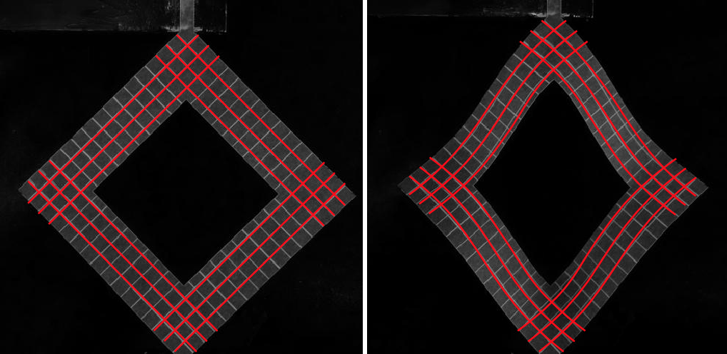
Apart from the above global characterizations of frame mechanics, we also probe local measures such as the nonuniform displacement field over the entire frame, thereby allowing for a stronger test of the theory. Using grid lines etched into the paper, painted black to improve the contrast in imaging, we measure the displacement field of the frame by comparing its projected mesh just past buckling to a reference undeformed mesh. As the uniaxial tensile load prescribes the orientation of the induced quadrupoles, with just the scalar charge magnitudes as fitting parameters, we find the entire spatial deformation field is well captured within our image charge framework (red lines in Fig. 3).
The quantitative success of our theory in describing the mechanics of isolated frames encourages us to take a step further and exploit the method of charges to analyze kirigami patterns, which now involves interactions between the charges in different holes. The elastic interaction energy of two planar quadrupoles a distance apart is given by Moshe et al. (2015b)
| (5) |
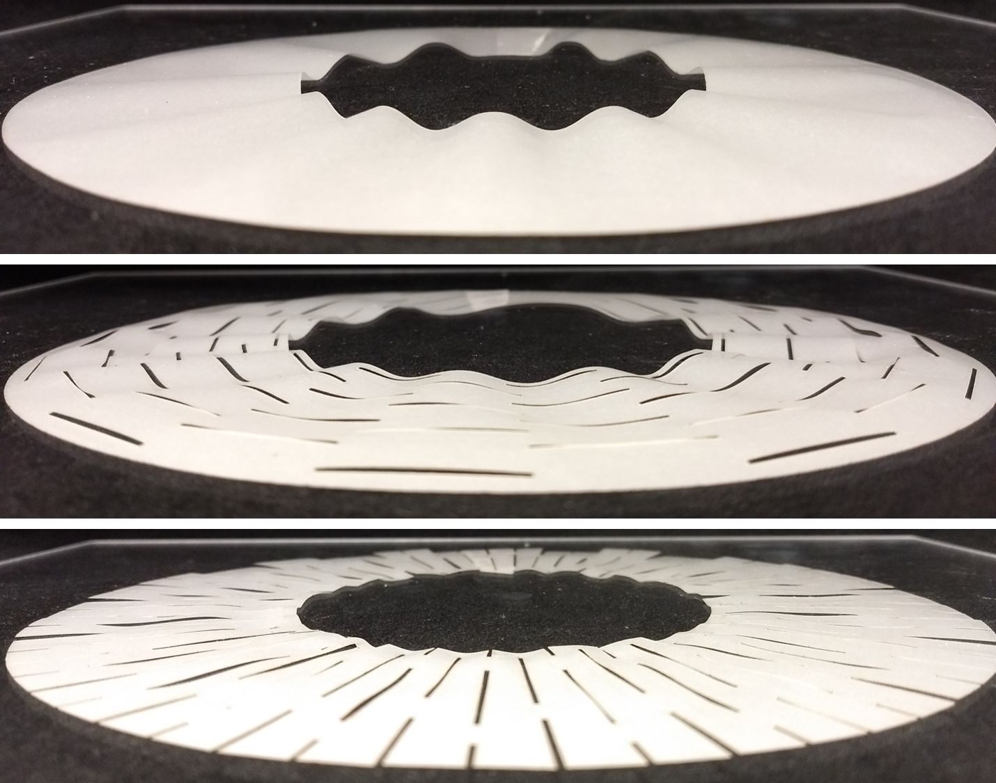
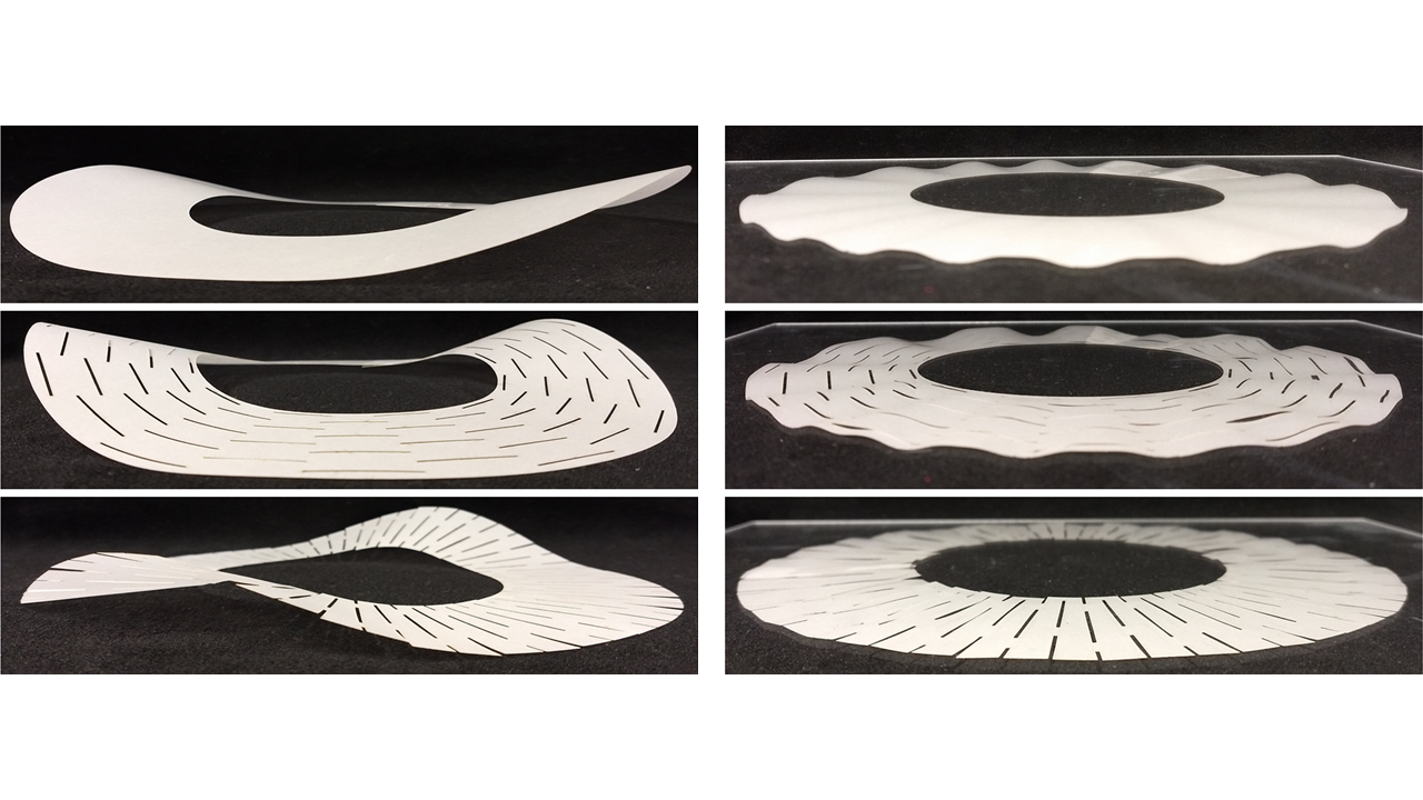
where the quadrupole angles are taken with respect to the pair separation . To demonstrate that interacting elastic charges can fruitfully guide design of kirigami meta-materials, we shall focus on the simple problem of a flattened cone as an example of the inverse problem in kirigami mechanics. A conical frustum (either with an angle deficit or excess) when confined with a small gap in the plane is stressed due to its intrinsic geometry, a state that can be relaxed for a sufficiently thin sheet by wrinkling (Fig. 4a). Patterning an appropriate kirigami design affords the sheet a new mechanism of locally relaxing in-plane stress without wrinkling. For the regular circular cone, minimizing the energy of an interacting pair of quadrupoles with the background stress field of a positive disclination, we find (see SI) that the equilibrium configuration favours azimuthally aligned quadrupoles. Unlike squares that lock the quadrupole orientation to their diagonals, slits only permit quadrupolar charges perpendicular to their long axis. Hence, while azimuthal slits leave the wrinkles unaltered (Fig. 4b), radial slits in a staggered array (which minimizes the charge-charge interactions) around the cone locally relax stress when flattened (Fig. 4c). Similar slit patterns also relax stresses in a flattened e-cone Müller et al. (2008) as shown in the SI.
In summary, we have proposed a useful elastic charge framework to understand kirigami mechanics in thin sheets with perforations. By relating the challenging nonlinear problem of post-buckling mechanics to the simpler pre-buckling computation within the planar problem, we were able to quantitatively test the analytical predictions against experimental measurements through both global and local measures of deformation. The inclusion of interactions between charges also suggests our framework can advise possible design strategies to pattern kirigami meta-materials that permit engineering pathways to locally relax elastic stresses. Addressing nonlinear and thermal effects are promising directions for future work.
We thank James Pikul, Marc Miskin, Winston Lee, for their valuable insights and help with guiding the initial experiments. We thank Paul McEuen, Kyle Dorsey, Tanner Pearson, and Zeb Rocklin for very useful conversations throughout the project. Work by IC was supported by a grant from the NSF DMREF program under grant DMR-1435829. Work by MJB was supported by the KITP grant PHY-1125915 and the NSF DMREF program, via grant DMREF-1435794. Work by DRN was primarily supported through the NSF DMREF program, via grant DMREF-1435999, as well as in part through the Harvard Materials Research and Engineering Center, via NSF grant DMR-1420570. MM acknowledges the USIEF Fulbright program. MM, SS & MJB thank the Syracuse Soft & Living Matter Program for support and the KITP for hospitality during completion of some of this work.
References
- Mullin et al. (2007) T. Mullin, S. Deschanel, K. Bertoldi, and M. C. Boyce. Physical review letters, 99(8):084301, 2007.
- Bertoldi et al. (2010) K. Bertoldi, P. M. Reis, S. Willshaw, and T. Mullin. Advanced Materials, 22(3):361–366, 2010.
- Florijn et al. (2014) B. Florijn, C. Coulais, and M. van Hecke. Physical review letters, 113(17):175503, 2014.
- Song et al. (2015) Z. Song, X. Wang, C. Lv, Y. An, M. Liang, T. Ma, D. He, Y.-J. Zheng, S.-Q. Huang, H. Yu, et al. Scientific reports, 5:10988, 2015.
- Zhang et al. (2015) Y. Zhang, Z. Yan, K. Nan, D. Xiao, Y. Liu, H. Luan, H. Fu, X. Wang, Q. Yang, J. Wang, et al. Proceedings of the National Academy of Sciences, 112(38):11757–11764, 2015.
- Lamoureux et al. (2015) A. Lamoureux, K. Lee, M. Shlian, S. R. Forrest, and M. Shtein. Nature communications, 6, 2015.
- Shyu et al. (2015) T. C. Shyu, P. F. Damasceno, P. M. Dodd, A. Lamoureux, L. Xu, M. Shlian, M. Shtein, S. C. Glotzer, and N. A. Kotov. Nature materials, 14(8):785–789, 2015.
- Wu et al. (2016) C. Wu, X. Wang, L. Lin, H. Guo, and Z. L. Wang. ACS nano, 10(4):4652–4659, 2016.
- Dias et al. (2017) M. A. Dias, M. P. McCarron, D. Rayneau-Kirkhope, P. Z. Hanakata, D. K. Campbell, H. S. Park, and D. P. Holmes. Soft matter, 13(48):9087–9092, 2017.
- Rafsanjani and Bertoldi (2017) A. Rafsanjani and K. Bertoldi. Physical Review Letters, 118(8):084301, 2017.
- Rogers and Huang (2009) J. A. Rogers and Y. Huang. Proceedings of the National Academy of Sciences, 106(27):10875–10876, 2009.
- Deng and Berry (2016) S. Deng and V. Berry. Materials Today, 19(4):197–212, 2016.
- Blees et al. (2015) M. K. Blees, A. W. Barnard, P. A. Rose, S. P. Roberts, K. L. McGill, P. Y. Huang, A. R. Ruyack, J. W. Kevek, B. Kobrin, D. A. Muller, et al. Nature, 524(7564):204, 2015.
- Eran et al. (2004) S. Eran, M. Marder, and H. L. Swinney. American Scientist, 92(3):254, 2004.
- Genzer and Groenewold (2006) J. Genzer and J. Groenewold. Soft Matter, 2(4):310–323, 2006.
- Witten (2007) T. A. Witten. Reviews of Modern Physics, 79(2):643, 2007.
- Li et al. (2012) B. Li, Y.-P. Cao, X.-Q. Feng, and H. Gao. Soft Matter, 8(21):5728–5745, 2012.
- Reis et al. (2015) P. M. Reis, H. M. Jaeger, and M. van Hecke. Extreme Mechanics Letters, 5:25–29, 2015.
- Bertoldi et al. (2017) K. Bertoldi, V. Vitelli, J. Christensen, and M. van Hecke. Nature Reviews Materials, 2(11):17066, 2017.
- Landau and Lifshitz (1986) L. D. Landau and E. Lifshitz. Theory of Elasticity,, volume 3. Elsevier, New York, 1986.
- Cerda et al. (2002) E. Cerda, K. Ravi-Chandar, and L. Mahadevan. Nature, 419:579–580, 2002.
- Cerda and Mahadevan (2003) E. Cerda and L. Mahadevan. Phys. Rev. Lett., 90:074302, 2003.
- King et al. (2012) H. King, R. D. Schroll, B. Davidovitch, and N. Menon. Proc. Natl. Acad. Sci. USA, 109:9716–9720, 2012.
- Ben Amar and Pomeau (1997) M. Ben Amar and Y. Pomeau. Proc. R. Soc. A, 453:729–755, 1997.
- Pocivavsek et al. (2008) L. Pocivavsek, R. Dellsy, A. Kern, S. Johnson, B. Lin, K. Y. C. Lee, and E. Cerda. Science, 320(5878):912–916, 2008.
- Moshe et al. (2018) M. Moshe, S. Shankar, M. J. Bowick, and D. R. Nelson. arXiv preprint arXiv:1801.08263, 2018.
- Isobe and Okumura (2016) M. Isobe and K. Okumura. Scientific reports, 6:24758, 2016.
- Koiter (1966) W. T. Koiter. Koninklijke Nederlandse Akademie van Wetenschappen, Proceedings, Series B, 69(1):1–54, 1966. See also A. M. A. van der Heijden, W. T. Koiter’s elastic stability of solids and structures, Cambridge University Press, 2009.
- Ciarlet (1997) P. G. Ciarlet. Mathematical elasticity: Theory of plates. North-Holland, 1997.
- Audoly and Pomeau (2010) B. Audoly and Y. Pomeau. Elasticity and geometry: from hair curls to the non-linear response of shells, 2010.
- Nelson (2002) D. R. Nelson. Defects and geometry in condensed matter physics. Cambridge University Press, 2002.
- Kupferman et al. (2013) R. Kupferman, M. Moshe, and J. P. Solomon. ARMA, 2015, 2013.
- Moshe et al. (2015a) M. Moshe, I. Levin, H. Aharoni, R. Kupferman, and E. Sharon. PNAS, 112(35):10873–10878, 2015a.
- Seung and Nelson (1988) H. Seung and D. R. Nelson. Physical Review A, 38(2):1005, 1988.
- Moshe et al. (2015b) M. Moshe, E. Sharon, and R. Kupferman. Physical Review E, 92(6):062403, 2015b.
- Müller et al. (2008) M. M. Müller, M. B. Amar, and J. Guven. Physical review letters, 101(15):156104, 2008.
Kirigami mechanics as stress relief by elastic charges
SUPPLEMENTARY INFORMATION
Michael Moshea,b, Edward Espositoc, Suraj Shankarb,d Baris
Bircane, Itai Cohenc, David R. Nelsona, and Mark J. Bowickb,d
aDepartment of Physics, Harvard University, Cambridge, Massachusetts 02138, USA.
bPhysics Department and Syracuse Soft and Living Matter Program,
Syracuse University, Syracuse, NY 13244, USA.
cLaboratory of Atomic and Solid State Physics, Cornell University, Ithaca, NY 14853, USA.
dKavli Institute for Theoretical Physics, University of California, Santa Barbara, CA 93106, USA.
eSchool of Applied and Engineering Physics, Cornell University, Ithaca, NY 14853, USA.
I I. Experimental Methods
The square frames are prepared by cutting them from full sheets of parchment paper (with Young’s moduli varying from Pa to Pa) using a W Epilog Zing laser. Vector cutting is performed at % power and % speed. For imaging the deformation, mesh grids are etched onto the specimens using the laser cutter’s raster setting at % power and % speed, and the back surface of the square is painted with a black oil paint to improve the contrast between the mesh and the body of the square. The cutting pattern also includes long, narrow tabs at opposite corners of the square, with dimensions mm mm. The tabs hold the frame fixed on the device.
A custom built force measurement setup is used to obtain the force-extension data of the square frame samples. The setup consists of a translation stage, equipped with a micrometer screw gauge, mounted to a Haydon-Kerk rail guided linear actuator (RGS08KR-M57-0250-18). The translation stage faces a polished aluminum plate mounted to a Loadstar force measurement sensor ( kg RSP1 load cell with DI-1000U interface). The linear rail system is interfaced with Windows using the proprietary IDEA Drive Software and driven by a stepper IDEA Drive Kit (PCM4826E-K). The load cell is interfaced with MATLAB and force measurements are collected using a custom MATLAB script. At each displacement, the load cell takes measurements over seconds which are then averaged to produce the single measurement value reported. Our protocol uses such measurements in steps of m, followed by measurements in steps of m until the frame tears.
For each trial, the tab at one corner of the specimen is fixed with a fast setting 3M Super Glue (Ethyl cyanoacrylate) to the aluminum plate, and the tab at the opposite corner is glued to the surface of the translation stage. After a trial, the specimen and glue are cut away from the surfaces using a razor. Remaining residues are removed from the surfaces using BSI UN-CURE debonder. The surfaces are then allowed to dry for several minutes between trials.
The zero of the load cell must be recalibrated between trials. With the specimen glued to the apparatus, it is difficult to determine by eye the proper zero of the displacement, and thereby to set the force to zero. Therefore, we begin each trial with the specimen under slight, but visible, compressive buckling. During extension the samples will shift from this compressed state to a stretched state. By aligning the transition region for the data on samples with different thicknesses and aspect ratios we obtain the scaling plots shown in the manuscript.
The cones are cut from the same Glama Natural parchment paper, of intermediate thickness ( cm). A full annulus is cut first. Then a wedge is either added or removed for the regular or the excess cone respectively, and the annulus is glued back together. The cones are photographed in their full three-dimensional configurations, and then are flattened under a quarter-inch thick piece of acrylic and photographed again in the flattened state.
II II. Interacting quadrupoles on a flattened kirigami cone
In the case of both an angle deficit (regular cone) or an excess (e-cone), the planar state of the cone is stressed and the Airy stress function is Seung and Nelson (1988), where is the angle excess or deficit from , the Young’s modulus and is the size of the sample. Both radial and hoop stresses are non-vanishing, while . For not too big samples with a sufficiently large core excised out, these stresses are relaxed in the absence of kirigami patterns by the formation of radial wrinkles when the sample is flattened in the plane, as seen for the regular cone in the main text and for e-cones here in Fig. S1.
Considering a periodic kirigami pattern of slits, as the quadrupole-quadrupole interaction decays quadratically with their separation Moshe et al. (2015), we restrict our analysis to nearest neighbour quadrupole interactions, which is the dominant term. Hence we have a pair of quadrupoles and at a separation in the presence of a background stress. Aligning the local coordinate frame so that the -axis conincides with the azimuthal direction, we have the total elastic energy
| (S1) |
where , is the angle made by with the -axis and are the angles of the quadrupoles measured from the -axis. This energy is minimized when the quardupoles align with the external field () and the angle of their pair separation is . So a staggered array of quadrupoles aligned in the azimuthal direction relaxes the stressed state of a flattened cone. The geometry of a slit is such that when pulled, negative partial disclinations form at its ends and the positive partial disclinations are spread around its length leading to the induced quadrupole direction being essentially orthogonal to the long axis of the slit. Using this, we immediately find that a radial staggered array of slits will locally relax stresses in a flattened cone.
References
- Seung and Nelson (1988) H. Seung and D. R. Nelson. Physical Review A, 38(2):1005, 1988.
- Moshe et al. (2015) M. Moshe, E. Sharon, and R. Kupferman. Physical Review E, 92(6):062403, 2015.