Ultracompact high-contrast magneto-optical disk resonator side-coupled to a plasmonic waveguide and switchable by an external magnetic field
Abstract
Here we propose and study a novel type of plasmonic resonators based on a metal-insulator-metal waveguide and a side-coupled magneto-optical disk controlled by an external magnetic field. The wavenumber change and the transmission of surface-plasmon-polaritons (SPPs) can be tuned by altering the magnetic field and reversible on/off switching of the running SPP modes by a reversal of the direction of the external magnetic field is demonstrated. Resonant enhancement of the magneto-plasmonic modulation by more than 200 times leads to a modulation contrast ratio more than tenfold ratio (90-%-modulation) keeping a moderate insertion loss within an optical bandwidth of hundreds of GHz. Numerical simulations confirm the predictions by the derived analytical formulas of a high-contrast magneto-plasmonic modulation by the submicron ultra-small disk resonator.
pacs:
73.20.Mf, 78.20.Ls, 75.50.Dd, 42.82.Et, 73.40.RwPlasmonic waveguide-ring and disk resonators are important building blocks for many nanophotonic device components and key elements in the next-generation of integrated nanophotonic circuits. They provide several functionalities, e.g. filtering, wavelength division multiplexing and efficient modulators in integrated photonics. Localized surface plasmon modes in plasmonic resonatorsYu et al. (2008a); Cai et al. (2009); Hu et al. (2011); Im et al. (2016) have been intensively studied for the enhancement of electromagnetic fields. However, plasmonic cavities have a low quality factor on the level of several tens which is not enough to achieve a high contrast in the modulation of the plasmons. In contrast travelling resonant modes in waveguide ring resonators (WRR) have a higher quality factor. A WRR consists of a circular optical resonator with an unidirectional coupling mechanism to a straight waveguide. For certain wavelengths a WRR is in resonance when the waves interfere constructively in the ring introducing a significant phase shift near the resonance and resonantly enhance the interaction. To date various ring resonators based on plasmonic waveguides have been investigated such as on channel plasmonic waveguides Bozhevolnyi et al. (2006), nano-plasmonic slot waveguides Zhu et al. (2011) or dielectric-loaded plasmonic waveguides Holmgaard et al. (2009). Ultra-small cavity mode volumes can be achieved in plasmonic waveguide disk resonators as studied e.g. in Hao et al. (2007); Large et al. (2011); Zhai et al. (2015); Randhawa et al. (2011); Kuttge et al. (2010); Bo et al. (2017).
Magnetoplasmonics using nanosystems with combined plasmonic and magnetic properties is a fast emerging new field and appealing for many applications. Including a magnetic material in a plasmonic structure provides a way of controlling plasmon propagation by using an external magnetic field (for a review see e.g. Armelles et al. (2013)). The magneto-optic effect allows switching that can be faster than those of other effects such as the electro-optic effect and thermo-optical effect. The magnetic field reversal by integrated electronic circuits can easily reach a speed in the GHz regime. Moreover, the recently demonstrated ultrafast magnetization switching with circularly polarized light enables a switching speed in the THz regime Stanciu et al. (2007). However, the performance of the ultrafast magneto-plasmonic modulators in the visible and near-infrared range generally suffers from a small change of the SPP wavenumber Sepúlveda et al. (2006); Khurgin (2006) which requires a device size of at least tens of micrometers to achieve a sufficient interaction between the external magnetic field and SPP. The wavenumber change could be enhanced by introducing photonic crystals Yu et al. (2008b); Kuzmiak et al. (2012) where the transmission bandwidth is limited by photonic bandgaps. Plasmon-enhanced transverse magneto-optical Kerr effect Belotelov et al. (2011); Kreilkamp et al. (2013); Belotelov et al. (2013) was experimentally demonstrated to be resonantly sensitive to the magnetically-induced change of the SPP wavenumber and allow a 50-%-modulation, but the corresponding structures are relatively bulky and not fully waveguide-integrated. A more compact magneto-plasmonic interferometer using a hybrid ferromagnetic structure was successfully demonstrated to present a 2-%-modulation requiring a waveguide length of 20 m Temnov et al. (2010, 2016), which can be improved to 12-%-modulation Armelles et al. (2013) by adding a dielectric layer with higher refractive index. Magneto-optical properties of nanowires (see e.g. Melle and Armelles (2003) and references therein) and of the resonant inverse Faradayeffect in nanorings Joibari et al. (2014); Koshelev et al. (2015) has been recently studied.
In this paper we propose and study a novel approach for traveling SPP resonators by using a metal-insulator-metal waveguide (MIM) with a side-coupled magneto-optical disk (see Fig.1). In such ultra-compact structure the plasmon resonance enhancement is combined with the resonator resonance enhancement. Wavenumber and transmission of the travelling SPPs depend on the external magnetic field and on/off switching is demonstrated by the reversion of the direction of the magnetic field. We find a strong enhancement of the magneto-plasmonic modulation due to a high quality factor of the SPPs. The modulation contrast ratio reaches more than tenfold ratio (90-%-modulation) keeping a moderate insertion loss within an optical bandwidth of hundreds of GHz. The fabrication of this kind of structure is possible within the current technology in this field. Recently, assisted by the rapidly developing nanotechnology, fabrication of circular or rectangular nanodisk cavity resonators have been reported, for examples (see e.g. Hao et al. (2007); Large et al. (2011); Zhai et al. (2015); Randhawa et al. (2011); Kuttge et al. (2010); Bo et al. (2017) and references therein).
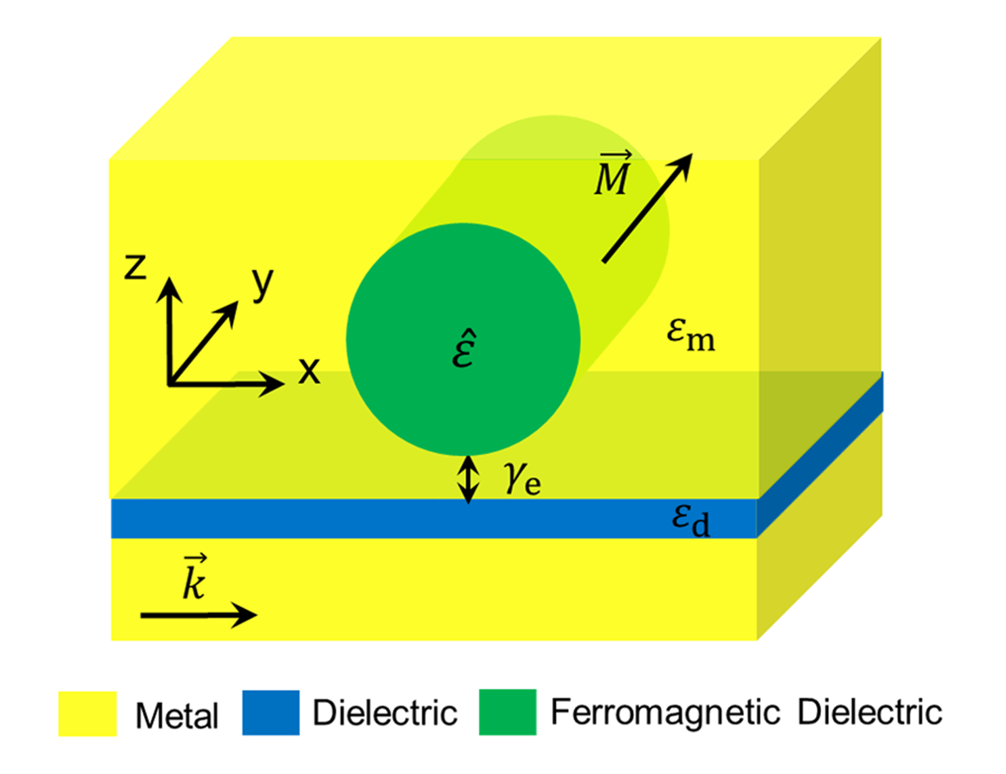
The geometry of a magneto-plasmonic disk resonator side-coupled to a MIM waveguide is shown in Fig. 1. Under an external magnetic field in the direction of y-axis, the permittivity tensor of ferromagnetic dielectric filling the disk resonator is expressed as
| (4) |
Here the gyration in the off-diagonal components is proportional to the magnetization, , where is the magneto-optical susceptibility. The permittivity of the metal is , where . For a sufficiently large disk radius, the wavenumber of the surface travelling magneto-plasmon approximates to that of the planar magneto-plasmon of a metal-ferromagnetic dielectric interface which is expressed as Im et al. (2017)
| (5) |
The resonance condition for the SPP modes is determined by the condition , where is an integer. The reonance frequency is sensitive to the disk radius and does not strongly depend on the other geometric parameters such as the waveguide thickness and the distance between the waveguide and the disk resonator. The resonance frequency is modulated by the external magnetic field as following.
| (6) |
The transmission of the SPP waveguide coupled to the disk resonator can be described by the temporal coupled-mode theory Manolatou et al. (1999) from which the following results can be received:
| (7) |
where and are the considered angular frequency and the resonant angular frequency, respectively. and are the input and the output power of the SPPs, respectively. and are the decay rates due to the absorption in the resonator and the escape rate due to the coupling between the waveguide and the resonator, respectively. If we assume the condition , which can be realized by adjusting the distance d between the disk resonator and the waveguide, at the frequency Eq. (3) and (4) lead to
| (8) |
Here, is the characteristic gyration, where is the quality factor of the surface travelling resonant mode of the unload disk resonator. Adjusting the magnetic field to the value , Eq. (5) leads to
| (9) | |||
| (10) |
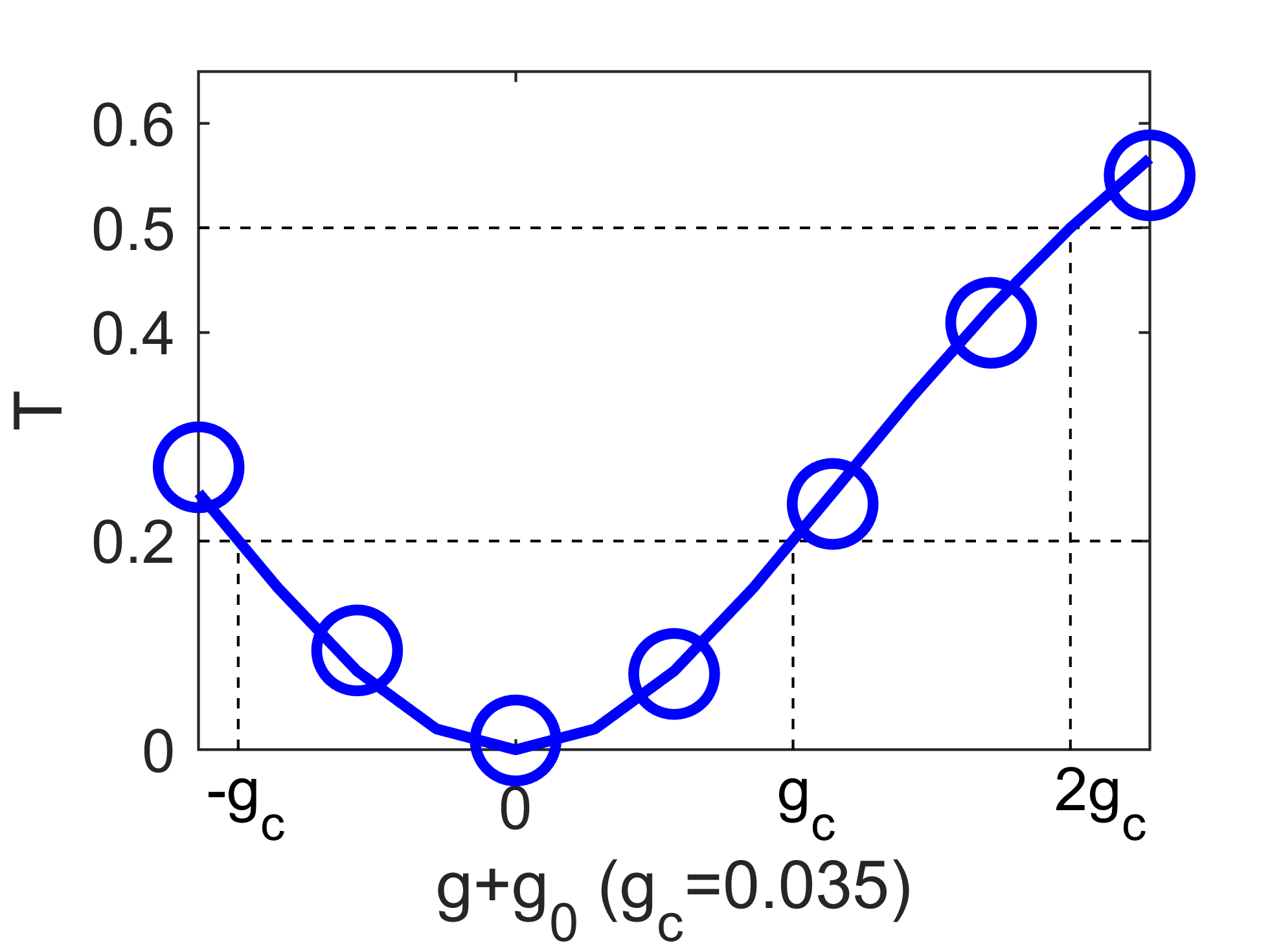
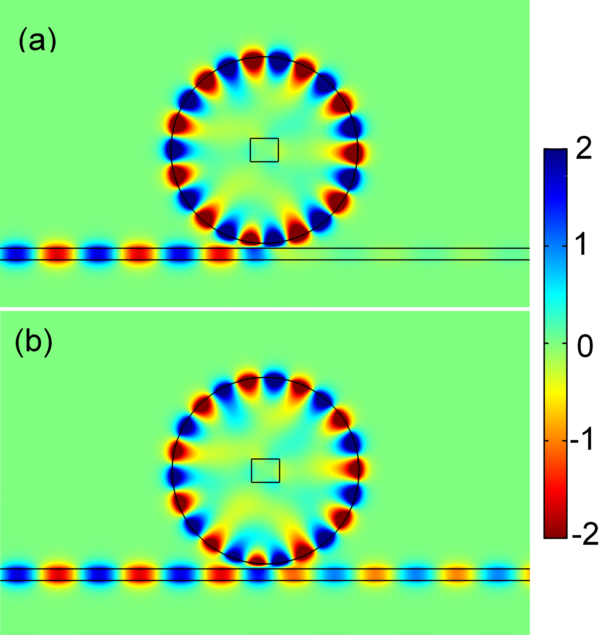
Eq. (6) means the SPPs are completely dropped for these parameters. With reversed direction of the magnetic field the transmission is expressed as Eq. (7). From Eq. (6) and (7), we can predict a high-contrast magneto-plasmonic modulation keeping a moderate insertion loss of if the gyration by the external magnetic field is on the level of the characteristic gyration . Let us first make a simple order-of-magnitude estimation of the magnitude of the characteristic gyration . The quality factor can be expressed as , where and are energies of the electric field and the magnetic field in the disk resonator, respectively. Using the relations , and and substituting the electric and the magnetic field distributions of the planar metal-dielectric interface Maier (2007), we find that is roughly estimated as .With the experimental data of the permittivity of silver Johnson and Christy (1972) as and and the permittivity of Bi-substituted iron garnet (BIG) Dutta et al. (2017) as , at a wavelength of 750 nm we can estimate . With calculated by Eq. (2), the characteristic gyration is about 0.03 which is in the order of magnitude of real ferromagnetic dielectrics Yao et al. (2015). We note that the gyration value for BIG saturates at 0.06 for B=150 mT (see the Methods of Ref. Davoyan and Engheta (2014)). Obviously, the wavenumber modulation of surface travelling magneto-plasmons is enhanced by the high quality factor , allowing a small characteristic gyration which is experimentally achievable. Fig. 2 shows the transmission of the SPPs in the waveguide side-coupled to the disk resonator as shown in Fig. 1 in dependence on the gyration of the ferromagnetic dielectric filling of the disk resonator. The blue circles have been obtained by numerical solutions of the Maxwell equation at the wavelength of 748 nm. The numerical results well agree with the prediction by the analytical formula Eq. (5) (the blue curve), where and have been assumed to fit the numerical results. Fig. 3(a) and (b) show the distributions of the magnetic field component of the SPPs at a gyration and of Fig. 2, respectively. As seen by changing the direction of the magnetic field the transmission of the SPPs is switched from an off to an on state via the changed interference pattern.
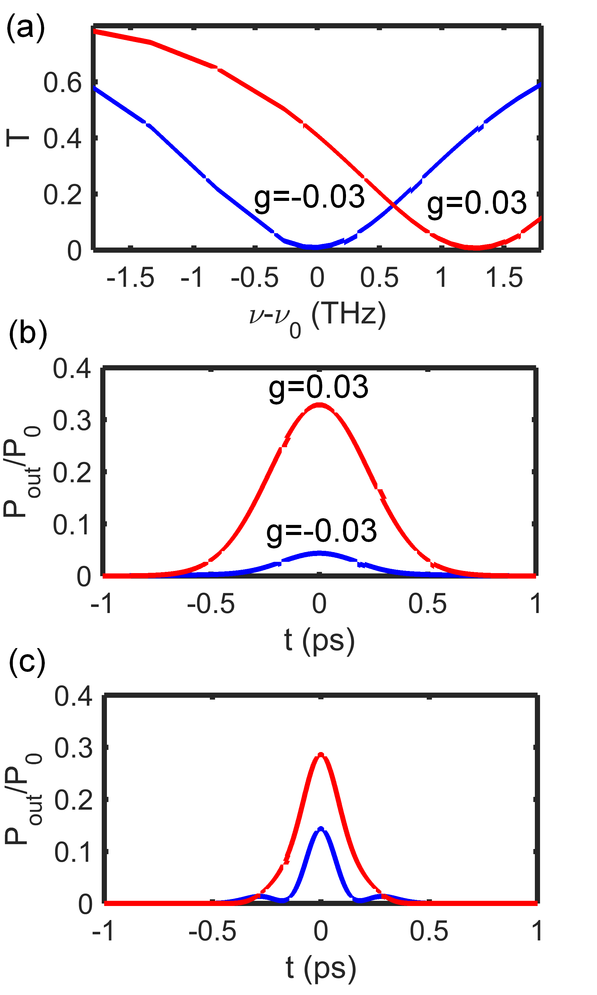
Finally, let us consider the optical bandwidth of the proposed magneto-plasmonic disk resonator. Fig. 4(a) shows the transmission in dependence on the frequency obtained by the numerical solution of Maxwell equations in the frequency domain Im et al. (2016). As seen a high contrast ratio of the transmission exceeding tenfold ratio (90-%-modulation) is maintained within an optical bandwidth of hundreds of GHz. The temporal responses to input SPP pulses have been calculated numerically by the superposition of the responses to the Fourier components of the input pulses. In the case of an input pulse with a FWHM of 500 fs [Fig. 4(b)], one can see a tenfold-contrast ratio keeping a moderate insertion loss. In the case of a FWHM of 200 fs [Fig. 4(c)], a lower contrast and even distortion of the pulse shape is obtained, which are attributed to the reduction of the optical bandwidth of the resonant device.
In conclusion, we investigated a novel type of an ultracompact plasmonic resonator based on a MIM waveguide side-coupled to a magneto-optical disk resonator. Wavenumber and transmission of the SPPs of the disk resonator are modulated by the magnitude of the magnetic field and on/off switching is demonstrated by the change of the direction of the magnetic field. Moreover, the high quality factor of the surface travelling magneto-plasmon resonant modes allows strong enhancement of the maneto-plasmonic modulation by more than 200. A tenfold-contrast ratio of the magneto-plasmonic modulator with a submicron footprint is maintained within an optical bandwidth of hundreds of GHz. The analytical predictions have been well supported by the numerical results.
References
- Yu et al. (2008a) Z. Yu, G. Veronis, S. Fan, and M. Brongersma, Appl. Phys. Lett 92, 041117 (2008a).
- Cai et al. (2009) W. Cai, J. White, and M. Brongersma, Nano Lett. 9, 4403 (2009).
- Hu et al. (2011) X. Y. Hu, Y. B. Zhang, X. N. Xu, and Q. H. Gong, Plasmonics 6, 619 (2011).
- Im et al. (2016) S.-J. Im, G.-S. Ho, D.-J. Yang, Z.-H. Hao, L. Zhou, N.-C. Kim, I.-G. Kim, and Q.-Q. Wang, Sci. Rep. 6, 18660 (2016).
- Bozhevolnyi et al. (2006) S. I. Bozhevolnyi, V. S. Volkov, E. Devaux, J. Y. Laluet, and T. W. Ebbesen, Nature 440, 508 (2006).
- Zhu et al. (2011) S. Y. Zhu, G. Q. Lo, and D. L. Kwong, IEEE Photonic Techn. Lett. 23(24), 1896 (2011).
- Holmgaard et al. (2009) T. Holmgaard, Z. Chen, S. I. Bozhevolnyi, L. Markey, and A. Dereux, Opt.Express 17(4), 2968 (2009).
- Hao et al. (2007) F. Hao, P. Nordlander, M. T. Burnett, and S. A. Maier, Phys. Rev. B 76(24), 245417 (2007).
- Large et al. (2011) N. Large, J. Aizpurua, V. K. Lin, S. LangTeo, R. Marty, S. Tripathy, and A. Mlayah, Opt. Express 19(6), 5587 (2011).
- Zhai et al. (2015) X. Zhai, Y. Liu, H. Li, R. Wujiaihenaiti, Y. Zhu, and L. Wang, J. Nanomater. 2015, 541409 (2015).
- Randhawa et al. (2011) S. Randhawa, A. V. Krasavin, T. Holmgaard, J. Renger, S. I. Bozhevolnyi, A. V. Zayats, and R. Quidant, Appl. Phys. Lett 98(16), 161102 (2011).
- Kuttge et al. (2010) M. Kuttge, F. J. G. de Abajo, and A. Polman, Nano Lett. 10, 1537 (2010).
- Bo et al. (2017) F. Bo, S. K. Özdemir, F. Monifi, J. Zhang, G. Zhang, J. Xu, and L. Yang, Sci. Rep. 7, 8045 (2017).
- Armelles et al. (2013) G. Armelles, A. Cebollada, A. García-Martín, , and M. U. González, Adv. Optical Mater. 1, 10 (2013).
- Stanciu et al. (2007) C. D. Stanciu, F. Hansteen, A. V. Kimel, A. Tsukamoto, A. Itoh, A. Kirilyuk, and T. Rasing, Phys. Rev. Lett. 99, 047601 (2007).
- Sepúlveda et al. (2006) B. Sepúlveda, L. M. Lechuga, and G. Armelles, J. Lightwave Technol. 24, 945 (2006).
- Khurgin (2006) J. B. Khurgin, Appl. Phys. Lett. 89, 251115 (2006).
- Yu et al. (2008b) Z. Yu, G. Veronis, Z. Wang, and S. Fan, Phys. Rev. Lett. 100, 023902 (2008b).
- Kuzmiak et al. (2012) V. Kuzmiak, S. Eyderman, and M. Vanwolleghem, Phys. Rev. B 86, 045403 (2012).
- Belotelov et al. (2011) V. I. Belotelov, I. A. Akimov, M. Pohl, V. A. Kotov, S. Kasture, A. S. Vengurlekar, A. V. Gopal, D. R. Yakovlev, A. K. Zvezdin, and M. Bayer, Nat. Nanotechnol. 6, 370 (2011).
- Kreilkamp et al. (2013) L. E. Kreilkamp, V. I. Belotelov, J. Y. Chin, S. Neutzner, D. Dregely, T. Wehlus, I. A. Akimov, M. Bayer, B. Stritzker, and H. Giessen, Phys. Rev. X 3, 041019 (2013).
- Belotelov et al. (2013) V. Belotelov, L. Kreilkamp, I. Akimov, A. Kalish, D. Bykov, S. Kasture, V. Yallapragada, A. V. Gopal, A. Grishin, S. Khartsev, M. Nur-E-Alam, M. Vasiliev, L. Doskolovich, D. Yakovlev, K. Alameh, A. Zvezdin, and M. Bayer, Nat. Commun. 4, 2128 (2013).
- Temnov et al. (2010) V. V. Temnov, G. Armelles, U. Woggon, D. Guzatov, A. Cebollada, A. García-Martín, J. M. García-Martín, T. Thomay, A. Leitenstorfer, and R. Bratschitsch, Nat. Photonics 4, 107 (2010).
- Temnov et al. (2016) V. V. Temnov, I. Razdolski, T. Pezeril, D. Makarov, D. Seletskiy, A. Melnikov, and K. A. Nelson, J. Opt. 18, 093002 (2016).
- Melle and Armelles (2003) S. Melle and J. L. M. A. G. Armelles, Appl. Phys. Lett. 83, 4547 (2003).
- Joibari et al. (2014) F. K. Joibari, Y. M. Blanter, and G. E. W. Bauer, Phys. Rev. B 90, 155301 (2014).
- Koshelev et al. (2015) K. L. Koshelev, V. Y. Kachorovskii, and M. Titov, Phys. Rev. B 92, 235426 (2015).
- Johnson and Christy (1972) P. B. Johnson and R. W. Christy, Phys. Rev. B 6, 4370 (1972).
- Dutta et al. (2017) A. Dutta, A. V. Kildishev, V. M. Shalaev, A. Boltasseva, and E. E. Marinero, Opt. Mater. Express 7, 4316 (2017).
- Im et al. (2017) S.-J. Im, C.-S. Ri, K.-S. Ho, and J. Herrmann, Phys. Rev. B 96, 165437 (2017).
- Manolatou et al. (1999) C. Manolatou, M. J. Khan, S. Fan, P. R. Villenueve, H. A. Haus, and J. D. Joannopoulos, J. Quantum Electron. 35, 1322 (1999).
- Maier (2007) S. A. Maier, Plasmonics: Fundamentals and Applications (Springer, New York, 2007).
- Yao et al. (2015) S. Yao, T. Sato, K. Kaneko, S. Murai, K. Fujita, and K. Tanaka, Jpn. J. Appl. Phys. 54, 063001 (2015).
- Davoyan and Engheta (2014) A. Davoyan and N. Engheta, Nat. Commun. 5, 5250 (2014).