Improved model for transmission probabilities of membrane bellows based on TPMC simulations
Abstract
Many complex vacuum systems include edge-welded bellows. Their simulation in the molecular flow regime with a Test Particle Monte Carlo (TPMC) code, such as MolFlow+, can take considerable amounts of computing power and time. Therefore we investigated the change of the transmission probability of a bellow compared to a cylindrical tube in TPMC simulations. The results were used to develop an empirical model to simplify the geometry of a bellow in a TPMC model by replacing it with a cylindrical tube of extended length, consequently compensating the reduced conductance of the bellow. The simulated transmission probabilities of a variety of different bellow lengths have been used to fit the parameters of the model. Each bellow geometry simulated with MolFlow+ comprised two cylindrical tubes, one at each end, and the central bellow section. The geometry of each bellow is described by two quantities. The first one is the total length of the geometry model normalized to the inner diameter of the bellow. The second one is the fraction of the bellow section with regard to the total length. Simulating a tube instead of a long bellow reduced the simulation time by a factor of up to 1000, while the error introduced through the replacement of the bellow with a cylindrical tube of modified length was in most cases negligible.
keywords:
Edge-welded bellow , transmission probability , improved model , TPMC simulation1 Introduction
Edge-welded bellows are important and common components of vacuum systems. Due to multiple scattering of gas particles inside the bellow elements, the transmission probability of gas particles through a bellow can be significantly reduced in comparison to a cylindrical tube of the same length. Therefore, when aiming for a realistic simulation of a vacuum system, edge-welded bellows can not be neglected without a loss of accuracy of the simulation. On the other hand, the inclusion of edge-welded bellows significantly complicates the simulation. In a typical Test Particle Monte Carlo (TPMC) vacuum simulation, the geometry of all components of the vacuum system is approximated e.g. by a triangle mesh. When comparing a cylindrical tube with a bellow of the same length, the latter increases the amount of triangles needed easily by a few orders of magnitude, therefore increasing the computation time of the simulation considerably. The increased number of hits of the walls inside the narrow bellow elements and the resulting longer trajectories until the particle leaves the bellow, add to the computation time, too. To our knowledge, empirical formulae for the transmission probabilities of edge-welded bellows have not been presented in the literature so far, while for the case of cylindrical tubes, empirical formulae for arbitrary tube lengths exist. The aim of this paper is to provide an empirical formula for the transmission probability of edge-welded bellows of arbitrary length. By using this formula, we propose a method for replacing edge-welded bellows with cylindrical tubes of appropriately adjusted length in vacuum simulations, which leads to a reduction of simulation time without a significant loss of accuracy.
The paper is organized as follows. In Sec. 2, we shortly explain the dynamics of rarefied gases, present analytic formulae for transmission probabilities for cylindrical tubes as given in literature and extend the discussion to the case of edge-welded bellows. In Sec. 3, we give a short introduction to the TPMC software MolFlow+ which is used for our TPMC simulations. We proceed to describe the principal method and relevant parameters of our bellow simulations. In Sec. 4, we present the results of our simulations and discuss the dependence of the transmission probability on the bellow element angle. Additionally, we propose a new empirical model for the transmission probability of edge-welded bellows in dependence of their geometry parameters and analyze the increase in computation time when including edge-welded bellows in a vacuum simulation in comparison to a cylindrical tube. We complete the analysis with a proposal of a method for removing edge-welded bellows from vacuum simulations, therefore decreasing the time needed for a simulation, without losing the desired accuracy of the simulation.
2 Dynamics of rarefied gases
2.1 Flow of rarefied gases through cylindrical tubes
The physical problem of the flow of rarefied gases through cylindrical tubes has been analyzed both theoretically and experimentally for a long time, e.g. by Knudsen who proposed analytic formulae for the conductance of cylindrical tubes and the gas rate that flows through them[1]. These formulae were corrected and improved by Smoluchowski[2] and Clausing[3]. The latter additionally derived an analytic formula of the transmission probability of cylindrical tubes with arbitrary length, i.e. the probability of a gas particle to flow through the tube, in the form of an integral equation. For tubes with arbitrary length and diameter , this integral can not be solved analytically in closed form, but it can be solved through numerical integration. For special configurations however, the integral is approximately solvable. For tubes that are very short compared to their diameter, Clausing found the analytic solution
| (1) |
while for very long tubes with respect to their diameter, the well-known limit
| (2) |
applies. For tubes with lengths between these two limits, the empirical formula
| (3) |
2.2 Flow of rarefied gases through edge-welded bellows
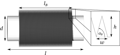
The geometry of edge-welded bellows is significantly more complex than that of cylindrical tubes. Depicted in Fig. 1 is a computer-aided design (CAD) model of a typical edge-welded bellow, consisting of two cylindrical tubes on both ends and the actual bellow element in between the two tubes111The geometry of hydroformed bellows, often used for systems where less flexibility is required, differs slightly from the triangular edge-welded CAD model presented in Fig. 1. In first approximation, the model is still valid, since the exact shape of the bellow element has only a minor influence on the transmission probability.. The geometry of the bellow is characterized by the total length of the tube , the inner diameter of the tube , the length of the bellow element and the height and width of a bellow segment, as depicted in the figure. Via the trigonometric relation
| (4) |
the height of the bellow is directly connected to the opening angle of the bellow segment. Gas particles that enter the bellow typically scatter numerous times inside the bellow segments. Depending on the geometry parameters of the bellow, this leads to an increased beaming effect towards the walls of the bellow or towards the inlet of the tube. As a consequence, edge-welded bellows have a lower transmission probability for gas particles than cylindrical tubes of the same length and diameter. Therefore, bellows are important and non-negligible components of vacuum systems, especially when aiming for an accurate simulation of the system.
The integral formula for the transmission probability as derived by Clausing was quite complicated even for the simple case of cylindrical tubes with arbitrary length. Due to the more complex geometry of edge-welded bellows, it is therefore not expected that an analytic formula for the transmission probability can be derived from first principles, and neither is it expected that such a formula would have a simple analytic solution. In order to quantify the transmission probability for a bellow, we use an ansatz that is motivated by the empirical form of Eqs. (1) and (3):
| (5) |
The coefficients are a priori undetermined and could be fixed by e.g. measurements or TPMC simulations. We want to point out that these coefficients depend on the other geometry parameters of the bellow. In the case of bellows used in actual vacuum systems, the bellow height and width are usually fixed. Hence, we choose the coefficients to depend on the length of the actual bellow element, only. As our analysis described in Sec. 4.1 shows, this is a valid approximation for typical bellows. In order to determine the parameters , we simulated several variations of bellows geometries as described in Sec. 3.2.
3 TPMC simulations of edge-welded bellows
Before we describe the method and parameters of our bellow simulations, we first explain the basic concepts of the TPMC program MolFlow+. The publicly available C++ code has been developed and maintained by R. Kersevan et al. [5] and is hosted by CERN [6].
3.1 Introduction to MolFlow+
The C++ code MolFlow+ is a TPMC program for the simulation of vacuum systems in the regime of molecular flow. The program allows both for the import of CAD geometries as well as the creation of models of vacuum systems inside MolFlow+ itself. In the following, we only want to present the basic concepts of the program. A detailed description of the functionality of the software can be found in [7].
When importing a model of a vacuum system into MolFlow+, the program approximates the geometry of the model by dividing it into a polygonal mesh, with the individual elements of the mesh being called facets. For each facet, the user can define its individual properties, e.g. the sticking coefficient of the facet, its outgassing rate or the reflection behavior of the facet with respect to colliding gas particles. In the TPMC simulation, the trajectories of gas particles start from the facets that are chosen as gas sources, with a rate corresponding to the outgassing rate, and their path through the vacuum set-up is tracked via a ray-tracing algorithm. Collisions of rays with a facet correspond to the gas particle hitting the respective wall of the vacuum set-up. The simulation ends when the gas particle is absorbed with a probability of by the corresponding facet. Otherwise, it is emitted again as another ray, usually following a cosine law. Three counters are assigned to each facet, counting the desorption, hit, and absorption of particles. The two main quantities, generated by the TPMC simulation, that are necessary for our analysis are:
-
1.
Desorptions : Total number of gas particles that are emitted from a source facet. In our simulation, particles are only desorbed from the inlet of the bellow.
-
2.
Absorptions : Total number of gas particles that are absorbed by a specific facet. In our simulations, the facet corresponding to the outlet of the bellow has a sticking coefficient , equivalent to an ideal absorber, while the rest of the facets have .
3.2 Method of the bellow simulations
For the TPMC simulation of the transmission probabilities with MolfFlow+ we constructed models of edge-welded bellows with a large variety of geometry parameters, as exemplarily depicted in Fig. 1. The models were designed using the open-source software Blender[8]. The circular entrance facet was defined both as a gas source and as an ideal absorber, i.e. . The outlet facet is only an ideal absorber. For all other facets, the sticking probability has been set to zero. This configuration corresponds to a set-up where gas particles enter the bellow only from one side, which is a valid approximation since we are only interested in the transmission probability of the bellow itself. The simulation of each bellow continued until the number of absorptions by the outlet facet was of the order , ensuring sufficient statistical accuracy. This quantity, together with the total amount of emitted gas particles , allows the calculation of the transmission probability by the formula
| (6) |
We performed two studies on the transmission probabilities of the bellows, as described in the following:
-
1.
Qualitative analysis of the transmission probability in dependence on the geometry parameters of the single bellow segments. For this study, we only considered the case of a pure bellow, i.e. we set , and a bellow segment with a fixed width . For the design parameter , two distinct, fixed values with were simulated. For these two values, the height of the bellow element was varied between the values in 13 steps, corresponding to opening angles . The results of this study are presented in Sec. 4.1.
-
2.
Quantitative analysis of the transmission probability in dependence of the total length and the length of the bellow . For this study, the geometry parameters of the bellow segments were fixed to the values and , corresponding to an angle . Both the total length of the tube as well as the length of the bellow element compared to the total length of the tube have been varied. For cylindrical tubes () three additional lengths were simulated at = 50, 500, and 5000, increasing the reliability of the fitted parameters to very long tubes. The results of this study are presented in Sec. 4.2.
4 Results of the simulations
In this section, we report the results of the simulations of the different geometries introduced in the previous section. Additionally, a procedure to remove edge-welded bellows from vacuum simulations is proposed, in order to save simulation time without introducing large errors due to the missing bellows.
4.1 Dependence of the transmission probability on the bellow angle
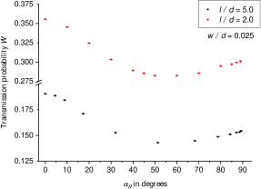
The first study investigates the dependence of the transmission probability on the geometry of the single bellow elements. The simulated transmission probabilities , together with their statistical error bars, are plotted in Fig. 2 as a function of the bellow element angle , defined in Eq. (4), for two distinct, fixed values of . While the absolute value of differs for the two different lengths of the tube, the functional dependence of on is approximately the same for both lengths. A qualitative analysis of the plot allows us to formulate three statements:
-
1.
The limiting case represents a cylindrical tube. In the vicinity of this value, the transmission probability is approximately independent of within a few percent. Additionally, for large values of , the transmission probability is approximately independent of as well.
-
2.
For all values , the transmission probability is lower than the one for , showing that in general, a bellow has a significantly lower transmission probability than a cylindrical tube of the same length.
-
3.
The transmission probability reaches a minimum for angles in the vicinity of .
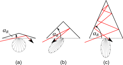
Qualitatively, one can understand these observations by physical reasoning. Illustrated in Fig. 3 is a single bellow element with trajectories of gas particles for (a) a very small bellow angle, (b) a bellow angle of around and (c) a very large bellow angle. In the illustration, the inlet of the bellow is on the left. For small angles, the bellow approximately resembles a cylindrical tube. Hence, the scattering of the gas particles is effectively the same as in the case of a tube. There is no increased backward beaming, since the bellow element acts as a nearly diffuse reflector. This reflective behavior is depicted in gray by the reflection distribution, in this case approximately given by a cosine distribution. For very large angles, the gas particles scatter frequently inside the bellow elements. The net effect of these numerous scattering events is that the gas particles leave the bellow element with an increased beaming towards the opposite wall of the bellow, as indicated by the gray reflection distribution. Due to this, the transmission probability becomes approximately independent of for large angles, since the beaming towards the opposite side of the bellow does not influence much. The large difference of transmission probabilities between large and can be explained by the reduction of particle trajectories emitted towards the outlet of the bellow, which would otherwise add to the strong forward beaming effect of long cylindrical tubes. Finally, for , the backwards beaming becomes maximal for the majority of bellow elements, leading to a minimal transmission probability for this angle, as indicated by the gray distribution function which is directed towards the entrance of the tube. Since the exact position of this minimum critically depends on all geometry parameters of the bellow, we restrict ourselves to this qualitative analysis.
4.2 New model for the transmission probabilites of bellows
For typical bellows, the geometry parameters are chosen such that and . As the qualitative analysis has shown, the transmission probability is nearly independent of in such cases, and consequently, the dependency of on and for edge-welded bellows is not taken into account in the quantitative model described in this section. With fixed values of and , the transmission probability can be fully parametrized as a function of and .
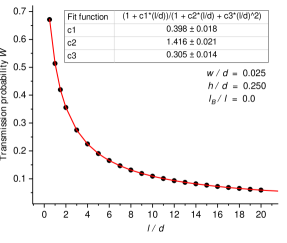
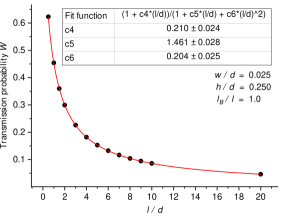
For the transmission probability function for an edge-welded bellow should turn into Eq. (5) for a cylindrical tube, which we call . The parameters in the formula are equivalent to the empirical result from Eq. (3). For the case of a pure bellow () the same ansatz is used, called , but with different parameters . The independent fits of the simulation results with Eq. (5) are shown in Fig. 4 for both cases.
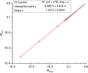
In order to test the consistency of the simulated data with the empirical formula in [4] for a cylindrical tube, we plotted the simulation results for the case over the results of Eq. (3). The resulting plot is shown in Fig. 5. The straight line fitted to the points has a slope . This demonstrates the excellent agreement between the widely used approximation of Eq. (3) and our TPMC simulations for cylindrical tubes.
The dots in Fig. 6 represent the simulated transmission probabilities for a variaty of geometry parameters and . For constant values of the simulation results show a linear drop between and . Thus, for arbitrary values of , the transmission probability can be interpolated by a linear equation:
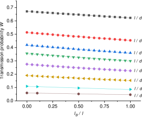
The full set of parameters has been determined by fitting Eq. (4.2) to all of the simulated data. The results for the six parameters are presented in Tab. 1, together with their statistical errors. The straight lines in Fig. 6 have been calculated with Eq. (4.2). They connect the simulated points which share the same value of . The individual simulations are in very good agreement with this empirical model. Due to the high number of simulated particles, the error of each result is of . For most of the points the error bars are too small to be visible. For values of the number of different simulations was restricted to fewer values, due to the rapidly increasing computation time. For the same reason the high statistics of adsorbed particles of could not be maintained for larger values of . It had to be reduced to adsorptions. The simulation of the single point at was stopped due to the long simulation time, after reaching a statistical uncertainty of better than 1%.
| Parameter | Fit value | Standard error |
|---|---|---|
| 0.2915 | 0.0020 | |
| 1.3018 | 0.0026 | |
| 0.2225 | 0.0015 | |
| 0.2707 | 0.0069 | |
| 1.5267 | 0.0077 | |
| 0.2777 | 0.0077 |
For the ratio of the transmission probabilities of a pure bellow and a cylindrical tube, parametrized by Eq. (4.2), converges against a constant value
| (8) |
For cylindrical tubes the transmission probability converges towards for , which agrees well with the literature value of Eq. (2). The transmission probability for pure bellows converges towards for .
4.3 Comparison of simulation time for bellows and tubes
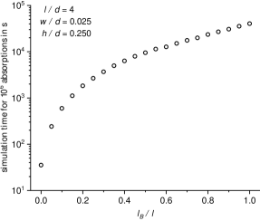
In order to investigate the effect of accurately modeled edge-welded bellows in a TPMC simulation with respect to the simulation time, the geometry parameter set , and is used as a benchmark. For values with steps of , each bellow model was simulated until the number of adsorptions reached on the outlet surface of the bellow. The required simulation time is shown in Fig. 7. As can be seen in the logarithmic plot, the simulation time considerably increases with the length of the bellow segments, represented by the fraction . For each additional bellow element, the number of facets in the simulation increases, as well as the time a particle spends trapped inside the narrow bellow elements. This leads to a non-linear increase of the simulation time. For values of with a simulation was not practicable anymore with the same accuracy, since the time required to reach adsorptions was too long. This analysis shows that bellows have a significant effect on the simulation time, which can rise by several orders of magnitudes.
4.4 Replacement of a bellow with an adapted cylindrical tube
Due to the substantial increase in CPU time when modeling an edge-welded bellow in a TPMC simulation, we suggest a method to optimize vacuum simulations without a reduction of the statistical significance of the result. The transmission probability of a bellow in a vacuum system can be estimated by Eq. (4.2). Since the simulation of a cylindrical tube with the same transmission probability as the bellow is much faster, one can replace the bellow by a slightly longer cylindrical tube with an effective length . The extended length would compensate the larger conductance of the tube with regard to the bellow. With the ansatz , one finds for the effective length
| (9) |
by inverting Eq. (4.2) for . Thus, for reducing the simulation time for vacuum setups containing edge-welded bellows, we propose the following approach:
- 1.
-
2.
Calculate the effective length of a cylindrical tube with the same transmission probability as the bellow, using Eq. (9).
-
3.
Replace the bellow in the TPMC model with a cylindrical tube of length .
The proposed substitution changes the angular distribution of the trajectories of the particles leaving the bellow. In long tubes the well known beaming effect is more pronounced than in bellows. Therefore, this method is most accurate if the bellow connects to vacuum chambers with larger dimensions than the diameter of the bellow, where the beaming effect plays only a minor role in the subsequent distribution of the simulated particles.
The transmission time through a tube is faster than the transmission time through a bellow, where the particles spend more time in the crevices of the bellow segments. Most TPMC simulations investigate the state of a vacuum system that has already reached equilibrium. However, if the dynamic development of the pressure over time is an issue, the proposed method should be used with a grain of salt.
Apart from these two special cases the proposed substitution of a bellow by a cylindrical tube with an appropriate length can lead to a considerable reduction of the simulation time.
5 Conclusions
We have simulated the transmission probability of edge-welded bellows for a wide range of design parameters with the TPMC code MolFlow+. An empirical model was developed to describe the results in a concise way.
The analysis shows that for typical edge-welded bellows, the geometrical parameters of the individual bellow elements, or more specifically, the bellow angle , has only a minor influence on the transmission probability. In most applications its influence can be neglected, leading to a quantitative description, which only depends on the ratio of the length and diameter of the bellow.
The quantitative model of , presented in this work, examined the more general case, where the bellow features cylindrical tubes at both ends. It is parameterized with the total length over diameter and the relative length of the bellow. For a fixed total length drops linearly with the increasing share of the bellow section. For fixed , the dependence of on follows the functional form of the commonly used empirical formula (Eq. 3) of the transmission probability for a cylindrical tube. The results from a large number of simulations with different bellow and tube lengths have been used to determine the six parameters of the model.
For very long bellows the model converges towards a constant ratio between the transmission probabilities of a bellow and a cylindrical tube. With the commonly used approximation for very long tubes, the transmission probability of long bellows can be estimated as within the errors of the simulations.
In an attempt to reduce the prohibitively long TPMC simulation times for long bellows, a method is proposed, where the empirical model is used to calculate the appropriate length of a cylindrical tube, which replaces the bellow in the TPMC model. This method can reduce the simulation time by several orders of magnitude, while preserving the statistical significance of the simulation.
Acknowledgment
We want to thank Roberto Kersevan and Marton Ady from CERN for making the source code of MolFlow+ 2.5 available to us. Additionally, we want to thank the KATRIN collaboration for supporting this work.
References
- [1] M. Knudsen, Die Gesetze der Molekularströmung und der inneren Reibungsströmung der Gase durch Rören, Ann. Phys. 333 1 p. 75, doi:10.1002/andp.19093330106
- [2] M. v. Smoluchowski, Zur kinetischen Theorie der Transpiration und Diffusion verdünnter Gase, Ann. Phys. (4)33 1559 (1910), doi:10.1002/andp.19103381623
- [3] P. Clausing, The Flow of Highly Rarefied Gases through Tubes of Arbitrary Length, Journal of Vacuum Science and Technology 8 5, (1971) 636 doi: 10.1116/1.1316379
- [4] K. Jousten (editor), Handbook of Vacuum Technology, Wiley-VCH, Weinheim (2008), ISBN: 978-3-527-40723-1, p. 227
- [5] R. Kersevan and J.-L. Pons, J. Vac. Sci. Technol. A 27, (2009) 1017
- [6] MOLFLOW+, molecular flow TPMC simulation code, CERN (2016), http://test-molflow.web.cern.ch
- [7] M. Ady and R. Kersevan, Molflow+ User Guide, CERN (2014)
- [8] Blender Foundation, Blender - a 3D modelling and rendering package, Blender Institute, Amsterdam, http://www.blender.org