Caging Loops in Shape Embedding Space: Theory and Computation
Abstract
We propose to synthesize feasible caging grasps for a target object through computing Caging Loops, a closed curve defined in the shape embedding space of the object. Different from the traditional methods, our approach decouples caging loops from the surface geometry of target objects through working in the embedding space. This enables us to synthesize caging loops encompassing multiple topological holes, instead of always tied with one specific handle which could be too small to be graspable by the robot gripper. Our method extracts caging loops through a topological analysis of the distance field defined for the target surface in the embedding space, based on a rigorous theoretical study on the relation between caging loops and the field topology. Due to the decoupling, our method can tolerate incomplete and noisy surface geometry of an unknown target object captured on-the-fly. We implemented our method with a robotic gripper and demonstrate through extensive experiments that our method can synthesize reliable grasps for objects with complex surface geometry and topology and in various scales.
1 Introduction
As an important type of robot grasping, caging grasps [1, 2, 3], as compared to force-closure grasps [4, 5, 6, 7], are advantageous in handling target objects with unknown or uncertain surface geometry and/or friction properties. This makes caging grasps more practically applicable in a wide spectrum of real scenarios. We are especially interested in a simple yet effective type of caging grasp formed by caging loops. A caging loop is a closed curve in three dimensional space computed around some part of the target object and used to guide robot grippers to form a caging grasp.
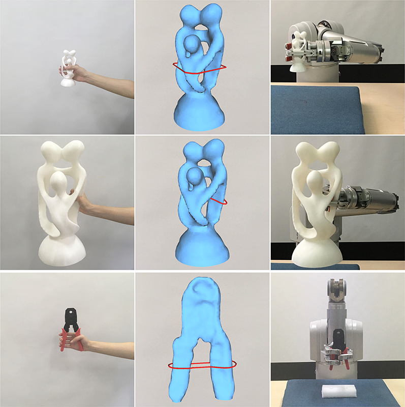
Existing methods on 3D caging grasp are based either on the geometric (e.g. [8]) or the topological (e.g. [9]) information of the target surface, or even both [10]. A common issue to these methods is that the computed caging curves seriously depend on topological and geometrical features of objects, while being oblivious to the relative size between the target object and the gripper. Taking the genus-4 Indonesian-Lady model in Fig. 1 for example. The six handles on the model are all seemingly good candidates for grasping. However, when the size of the model is too small compared to the robot gripper, these handles will no longer be graspable since the holes may be too small for the fingers to pass through. In such case, a more feasible grasp would be enclosing the object with a loop encompassing multiple handles (see Fig. 1(top) and Fig. 2(a)).
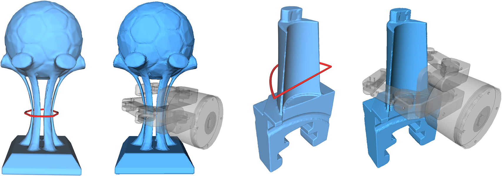
Another issue with geometry-based caging curves is that they easily lead to non-convex spatial curves which are not suited for guiding the gripper configuration. The example in Fig. 2(d) demonstrates such case, where the gripper penetrates into the object due to the non-convexity of the caging loop. Estimating a convex hull for the spatial loop still cannot guarantee a penetration-free configuration.
1.1 Motivation And Contribution
These examples motivated us in seeking to “fill up” those small topological holes and “smooth out” the geometric details on the target surface, before computing caging curves. Therefore, we advocate computing caging loops in the embedding space of the target surface, through a topological analysis of the distance field defined for the target surface in the embedding space.
We conduct a theoretical study on the fundamental relationship between caging loops and Morse singularities (including minimal, maximal and saddle points) of a spatial distance function. Based on that, we develop an algorithm of caging loop extraction through saddle point detection and analysis, within a proper grasping space defined in account of the gripper size. Working with a distance function defined in the embedding space naturally decouples the shape of caging loops from the geometric details of the target surface, while still keeping them aware of the overall shape of the target object. The caging loops are properly placed and scaled based on the relative size of the gripper against the target shape, rather than always tied with a specific handle as in traditional approaches.
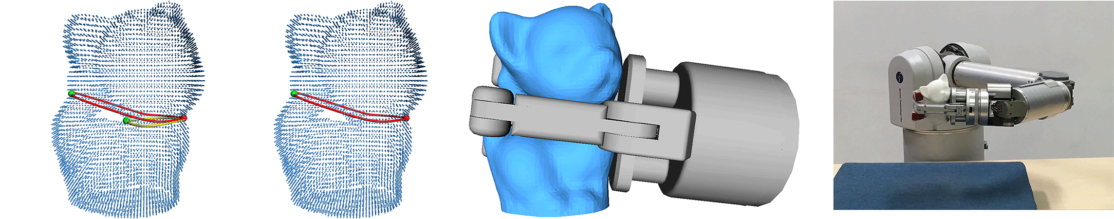
Another benefit of working in embedding space is the tolerance of incomplete and noisy surface geometry of the target object. This makes our method especially suited for synthesizing grasps for unknown objects which are captured and reconstructed on-the-fly, with a minimal effort of robot observation. In our implementation (see Fig. 4), two depth cameras are deployed to capture the target object from two (front and back) views. Even with such a sparse capturing and low-quality reconstruction, our method can still synthesize feasible caging loops for robust grasping.
We found this simple idea leads to a robust and efficient algorithm, with theoretical guarantees. We implemented our algorithm in a grasping system composed of a Barrett WAM robotic arm with a three-finger gripper and two Xtion Pro RGB-D cameras. Only depth images are used for reconstructing the target surface based on the depth fusion technique [11]. We have conducted numerous evaluations with both synthetic and real examples to evaluate the performance of our method. We show that our system is able to robustly grasp objects with complex surface geometry and topology and in various scales.
Our work makes the following contributions:
-
•
We propose a novel method for caging grasp synthesis through topological analysis of shape-aware distance field defined in shape embedding space. The method is able to generate relative-scale-aware caging loops for unknown objects captured on-the-fly.
-
•
We provide a rigorous study on the relation between the topology of distance field and caging loops, based on Morse theory, and derive a robust algorithm for caging loop estimation. We also provide a handful of provably effective techniques to reduce the computational cost of our method.
-
•
We implement our method in a grasping system using robot gripper, and conduct thorough evaluations and comparisons with both synthetic and real objects.
(a) (b)
(c) (d)
1.2 Related Work
Robot grasping is a long-standing yet actively studied research topic in the fields of robotics and vision. Force-closure and caging are two typical approaches that have been developed to synthesize grasps. Force-closure methods [12, 13, 14, 15, 5, 4] concentrate on finding a stable grasping configuration for the grippers where a mechanical equilibrium is achieved. The advantage of such approach is that the synthesized grasps are usually physically feasible. The method, however, requires that the 3D shape of the target model is known a priori and cannot tolerate much the surface defect such as missing data. Furthermore, the contact area between the gripper and the target surface is often small, leading to unsteady grasps.
Caging grasps [3], as compared to force-closure ones, seeks for a sufficiently large contact area and thus are deemed to have better stability, although they are not designed to directly reach a mechanical equilibrium. The key benefit of caging [3] is that it is robust to surface uncertainty and imperfection. This makes it especially applicable to unknown objects being captured and reconstructed on-the-fly. Some works studied the computation of planar cages in 2D space for planar objects [16, 17, 18, 19]. Most existing approaches to 3D object caging rely on the topological structure of the target surface [9, 20, 21]. Some further take geometry information into account [10]. However, such approaches cannot compute a caging loop encompassing multiple handles or deal with different relative scales between the gripper and the target object.
The Morse theory, as a connection between geometry and topology, has been widely utilized in the graphics and visualization fields [22, 23]. In our approach, the core algorithmic step is to find a caging loop according to a -based distance field, where is a point in the grasping space. At this point, the Morse theory is used to build a fundamental relationship between caging loops and Morse saddle points.
2 Theory
2.1 Grasping Strategy
In order to define a caging loop, we have to consider at least geometric and mechanical aspects. The geometric considerations include:
-
•
A caging loop encompasses the target object - any penetration into the target shape is not allowed.
-
•
A caging loop encloses some part of the target object tightly, i.e., cannot be shortened with respect to a slight perturbance (i.e., stable grasp) or at least goes around the target object like a great circle enclosing a sphere (i.e., unstable grasp).
-
•
A caging loop should roughly match the real robot gripper size.
On the other side, the mechanical considerations include
-
•
The center point of a caging loop should be as close as possible to the center of gravity of the target shape so as to minimize the moment of intertia.
-
•
A caging loop should be roughly horizontal so that the target object can be taken up steadily.
Our strategy is to compute a collection of caging loop candidates in consideration of the above-mentioned geometric principles. For purpose of efficient computation, we also invent a set of filtering techniques to reduce the number of loop candidates as far as possible.
2.2 Mathematical Formulation
Imagine the scenario of a caging grasp where the fingers of the gripper stretch to two opposite directions, roughly forming a loop; See Fig. 1 and Fig. 2. In the following, we shall formally characterize in which space we extract caging loops and systematically establish properties of caging loops.
The surface of the target object, typically represented as a watertight mesh, divides the whole space into interior parts and exterior parts, where only the visible free space (the outmost surface exterior space) is helpful to determine a real grasp configuration. Rather than constrain caging loops lying on the target surface , we relax caging loops from to the shape embedding space.
Definition 2.1
The visible free space separated by the target surface is called the grasping space.
Generally speaking, a stable grasp is desired, i.e., the caging loop encloses some part of the target object tightly and cannot be shortened even with a slight perturbance. In some rare cases, however, an unstable grasp like a great circle enclosing a sphere is also acceptable. Both cases imply that there is a fundamental relationship between caging loops and locally shortest loops in the grasping space.
Definition 2.2
Suppose the target object defines a grasping space . A closed curve is called a caging loop candidate if and only if is locally shortest everywhere, i.e., for any point , any sufficiently short segment of around cannot be shortened any more. All such loop candidates constitute a caging loop space, denoted by .
Property 2.3
Each caging loop touches the target surface at three or more points.
Proof. Without loss of generality, we assume that touches the target surface at only one point . Then the open curve lies in the grasping space but doesn’t touch . Considering that a locally shortest curve in must be a straight line segment, cannot include a bending point. Furthermore, is not only the start point of the straight line segment but also its endpoint. Therefore, degenerates into a single point under the above assumption, which contradicts to the given condition that is a caging loop. Similarly, it can be shown that the case of two touching points is impossible.
We can further show that each caging loop consists of an alternative sequence of straight line segments in the grasping space and geodesics on the target surface.
Property 2.4
Let be the target surface. Each caging loop consists of an alternative sequence of geodesic paths lying on and straight line segments in the grasping space , where a geodesic segment may degenerate into a single point.
In fact, the loop space includes all geodesic loops constrained on the surface and thus cannot be empty, which can be easily verified from the Lusternick-Schnirelmann theorem [24].
Theorem 2.5
is non-empty.
However, it is difficult to directly extract a caging loop without any further hint. Therefore, we consider a type of relaxed caging loops.
Definition 2.6
Suppose the target object defines a grasping space . Let be a point in . A closed curve is called a -based caging loop candidate if and only if is locally shortest everywhere except at . When is taken over all points in , all such loop candidates constitute a different caging loop space, denoted by .
We immediately have the following property.
Property 2.7
is a superset of .
Remark: Each loop carries a base point . If we eliminate those loops that are not locally shortest at the corresponding base point, then becomes . Therefore, the above property implies that we can select the desirable caging loop from .
3 Methodology
3.1 Computing Loop Candidates

Let be a point in the grasping space . For each point in , we use to denote the length of the shortest path connecting and . is called the distance field rooted at . Note that the distance is measured in rather than on the target surface.
Suppose that is a -based loop in the caging loop space . It is easy to know that there is a point such that divides into two equal-length parts. Obviously, both the two sub-curves are locally shortest paths in the grasping space . In the following, we shall reveal the fact that there is a fundamental relationship between Morse theory and caging loops.
Theorem 3.1
Suppose that the target object defines a grasping space . Let be the distance field rooted at . Each Morse saddle or maximal point of is able to define a -based caging loop.
Proof. Let be an Morse saddle (or maximal) point of . Since there exists a pair of shortest paths that go along opposite directions at . By combining , we get a -based caging loop.
Although the above discussion is assumed in the continuous setting, Morse-Smale theory is also well defined in the discrete setting; see more details in [23]. We can inherit the spirit in [23] and distinguish Morse saddle points, minimal points and maximal points by considering the relative magnitude at a voxel and its neighboring voxels. As Fig. 3 shows, we label ’s neighbor with a “+” if the neighbor has a higher value and a “-” otherwise. It is easy to know that there are at most possible configurations. Fig. 3 gives a typical situation of Morse saddle point, where two opposite neighbors are labeled with “-” while the other four neighbors are labeled with “+”. Similarly, a voxel is classified as a maximal point if all 6 neighbors are labeled with “-”.
Based on Theorem 3.1, it is natural to devise a naïve algorithm (see Algorithm 1) to build the -based caging loop space .
3.2 Filtering Rules
However, is very large generally. We need to invent a handful of filtering rules to reduce the computational cost. First of all, the reduction of the grasping space is much helpful to filter out redundant caging loops.
Theorem 3.2
Let be the convex hull of the target surface . Any caging loop must lie between and .
Secondly, Property 2.3 asserts that the base point can be constrained on the target surface , which cannot cause missing any useful caging loop. In fact, the location of can be more restricted; See the following theorem.
Theorem 3.3
For a point on the target surface , if both the principal curvatures are negative, cannot determine a caging loop.
Proof. Suppose is a caging loop. The sufficiently short segment of around can be viewed as the intersection between a normal plane at and the target surface . Since both the principal curvatures at are negative, the loop can be shortened by moving toward a little bit, leading to a contradiction.
Finally, even if the base point is given, there is no need to compute the entire distance field since an overly long loop is no use for grasping. It is sufficient to limit the sweep process in an appropriate range comparable to the gripper size. In practice, it is reasonable to require that the total stretching length of the robot gripper (twice as long as the gripper finger), denoted by , should be larger than one half of the length of the caging loop. Therefore, during the computation of the -based distance field, we can terminate the sweep process when the sweep radius amounts to since at this moment, any -based caging loop longer than has been found.
Taking the above speedup techniques simultaneously into consideration, we give an advanced algorithm for computing caging loops; See Algorithm 2 (the difference from Algorithm 1 is underlined).
4 Implementation
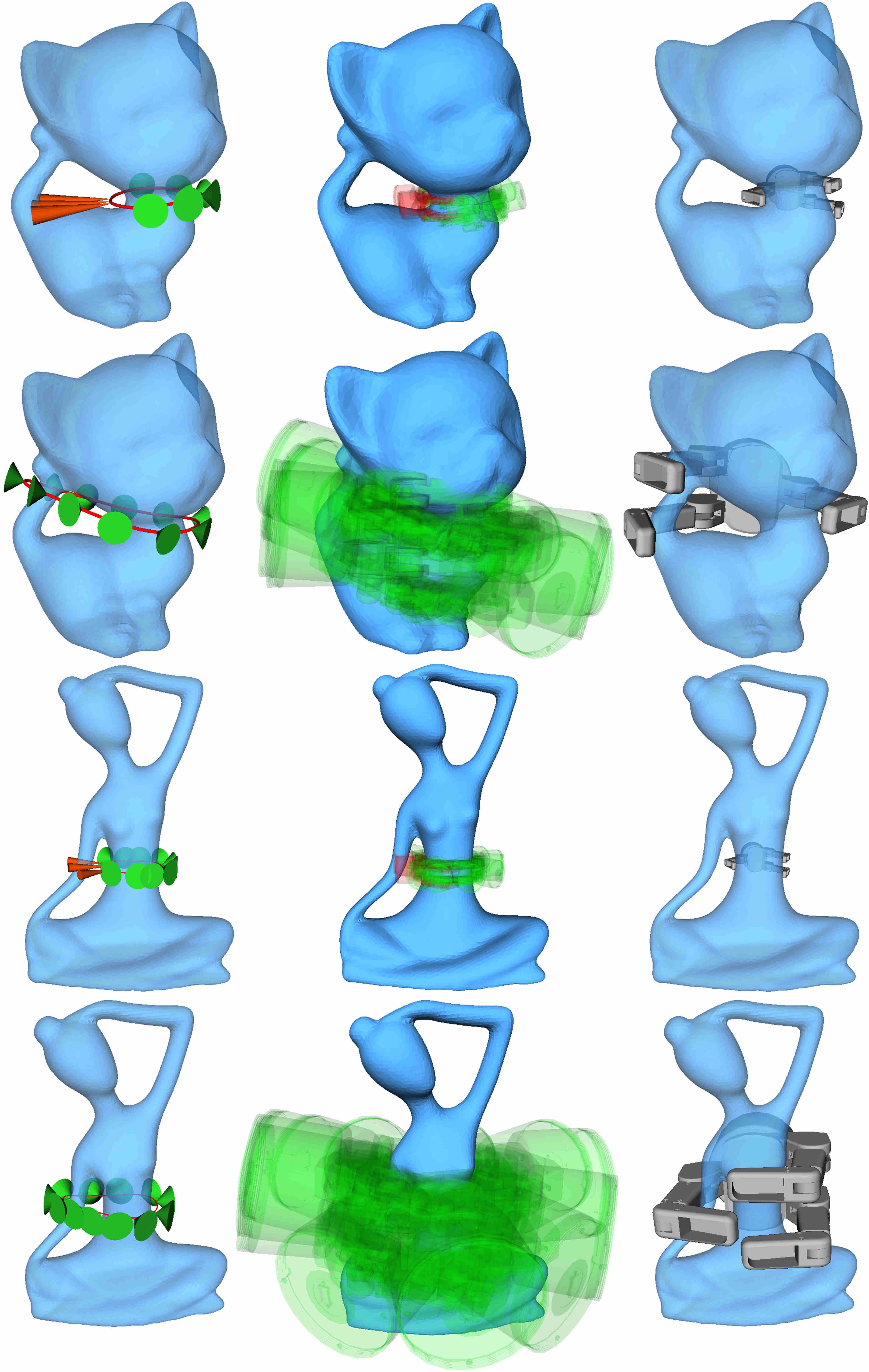
In a real grasping scenario, the gripper thickness cannot be negligible - a gripper cannot stretch into small topological holes or gaps. A commonly used technique is to filter out those infeasible caging loops by checking interference. Rather than leave it to ex post interference analysis, in this paper, we take each gripper finger as a skeleton curve equipped with a sweep radius . In implementation, we offset the target surface outward in a distance of and require any caging loop to be lying in the grasping space separated by the -offset surface . Fig. 4 shows an implementation details of our approach.
(a) (b) (c) (d)
(e) (f) (g) (h)
4.1 Grasping Space
Given a scanned point cloud of the target shape, we shall adapt the radial basis function (RBF) technique [25] to represent the -offset surface , which is central to define the grasping space . The general RBF with regard to is defined as follows:
where is the basis function used in our experiments, and the weighting coefficients and the low-degree (typically linear) polynomial is undetermined. Taking into the RBF, we have
Furthermore, considering that the point that lies on the -offset surface ,, we have
where is unknown. At the same time, in the RBF based approach, the four side conditions are
The above formulation can be finally transformed into a linear system from which we can immediately compute and . To this end, we find an implicit surface to represent the -offset surface . If the shape embedding space is discretized into voxels, it is very easy to identify outside voxels that meet , which can be viewed as a discrete representation of the grasping space .
4.2 Gripper Configuration
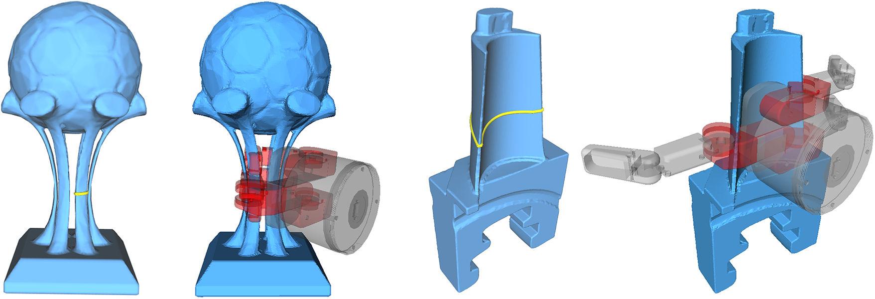
Upon obtaining a desirable caging loop , we need to determine the origin position of the gripper, as well as an orthogonal frame to set the gripper orientation, which facilitates a real grasp. Suppose that is represented by a point sequence . Imagine that there is an inward cone rooted at and the center line of the cone coincides with the normal vector at ; See Fig. 5. (If is not located on , the normal vector is discussed later.) We further define to be the maximum open angle under the condition that no penetration occurs between the inward cone and the target shape. The origin point is then selected from so as to maximize the opening angle. Let be the center point of . We then define the first direction as follows:
which roughly means the forward direction of the gripper. Considering that the loop is roughly a planar curve, we can fit using a plane where is a unit vector. Finally, we define as follows:
If the triple is able to define a valid grasping configuration (no global interference happens), we use it to guide the orientation of the gripper and launch a real grasp. In our experiments, the gripper will spread its fingers and move to the point first. It then wraps the target object tightly with the hint of and .
In Fig. 5, we show some examples on how to find a valid grasping configuration assuming that a desirable caging loop has been found. The key step is to check global interference in the simulation environment of OpenRAVE. It can be observed that our approach can report different gasping configurations on the same model with different sizes.
Remark: If is not located on , is given by , where is the tangent direction of the loop at and is the normal to the fitting plane of .
5 Experimental Results
We conducted both simulation and mechanical experiments to validate our approach. In this section, we first test the effectiveness of our algorithm on a variety of complex objects. We then show that our algorithm can be applied to 3D shapes with various levels of noise and geometric features. After that, we demonstrate the superior caging ability of our approach on real grasping scenarios (the digital models of the target objects are unknown in advance). Finally, we give the timing statistics of the main computational steps.
5.1 Test on High-genus Models in Various Sizes
(a) (b)
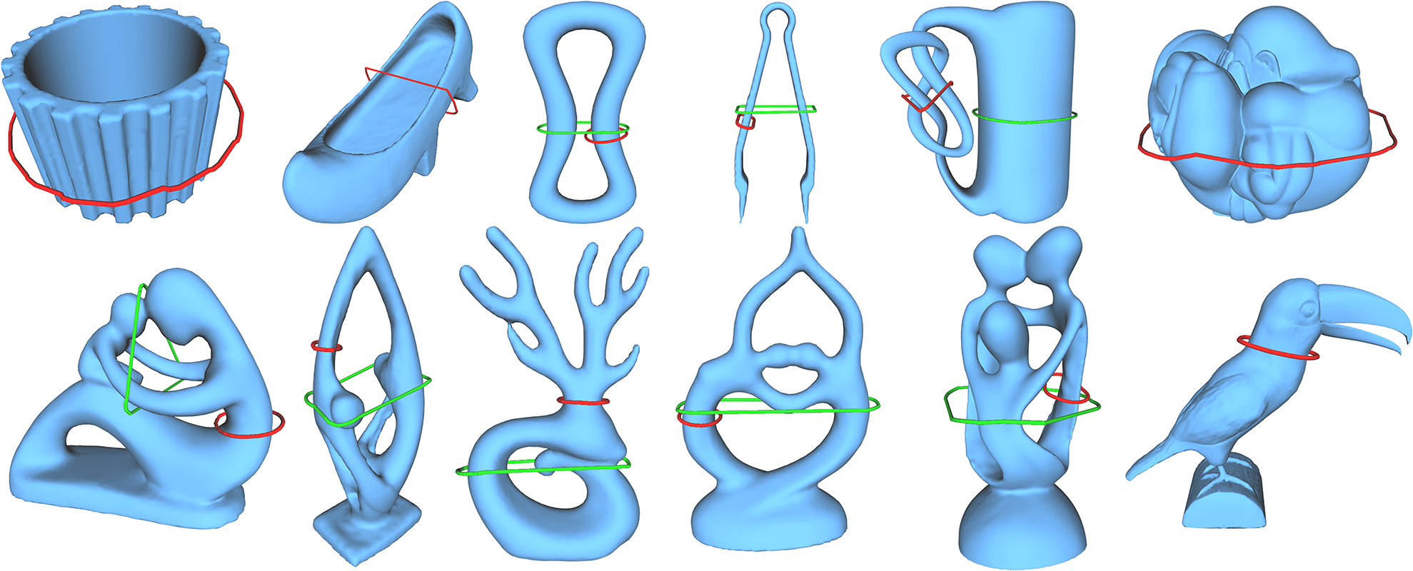
There are a number of research works on caging a 3D shape, which largely fall into one of the following three categories: topology guided [9], geometry guided [8] and topology & geometry guided [10, 26]. Existing approaches, whether topology guided or geometry guided, consider only those loops constrained on the target surface. Therefore, it is hard for them to deal with small topological holes or small gaps. As shown by the comparison in Fig. 6, our algorithm handles 3D shapes with small topological holes and is aware of the relative size between the gripper and the shape. More caging loop examples can be found in Fig. 7.
5.2 Test on Models with Various Levels of Noise and Geometric Feature
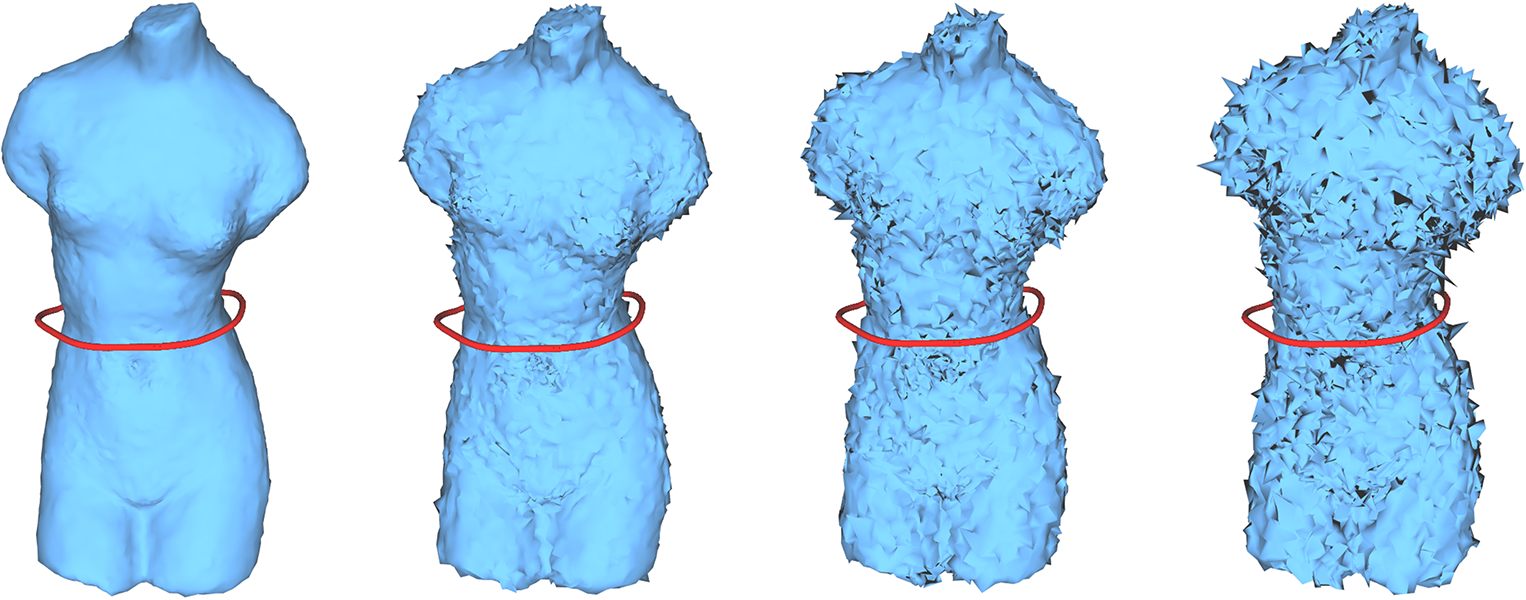
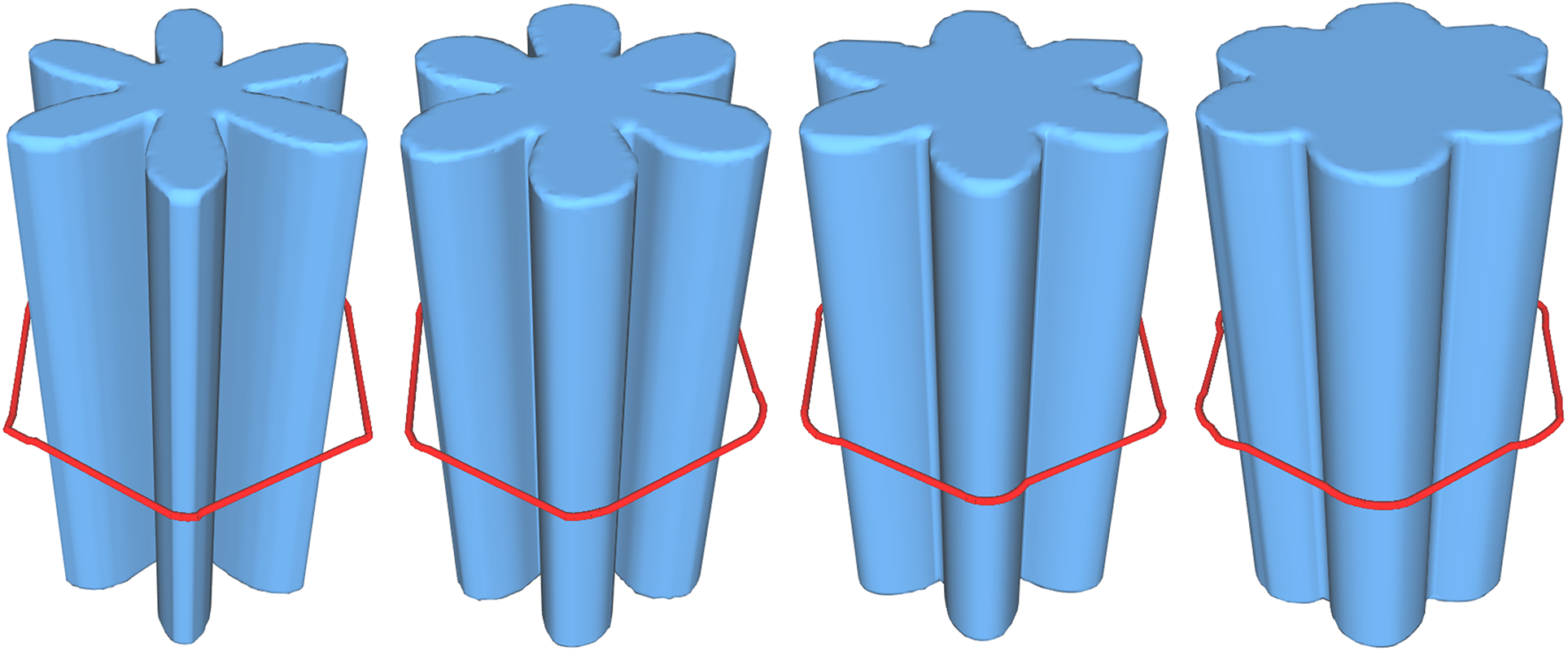
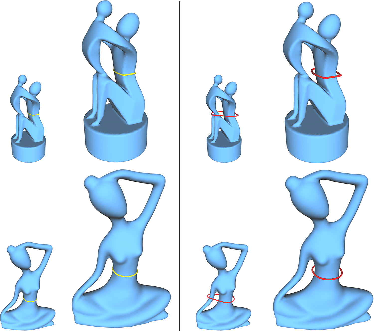
In real grasping scenarios, the target object is often scanned into a point cloud with noise. Therefore, a key criteria to evaluate a caging algorithm is whether it is robust to geometric noise or variations. In Fig. 8, the top row shows a group of caging loops on the Venus models with various levels of noise, while bottom row shows a group of caging loops on the Pillar models with various levels of geometric details. Both of them exhibit the robustness of our algorithm against geometric noise and details.
5.3 Test on Real Objects
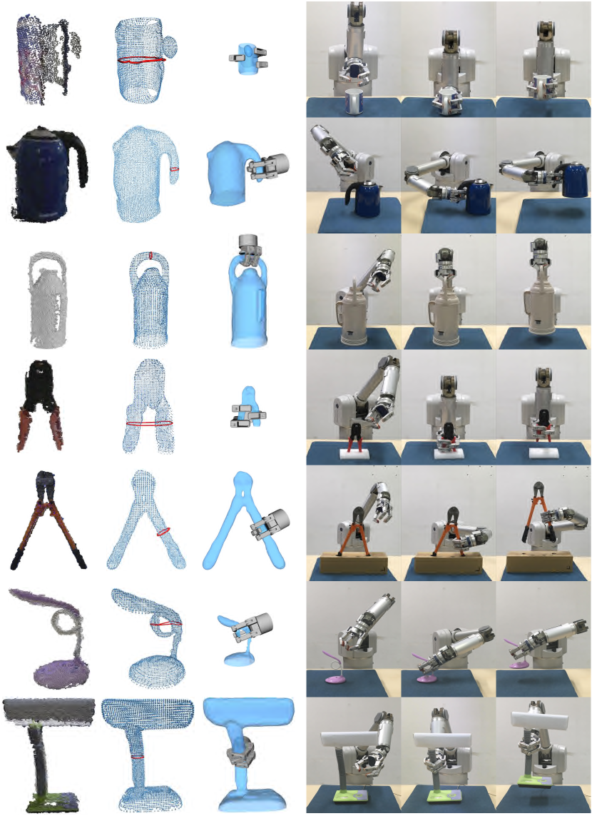
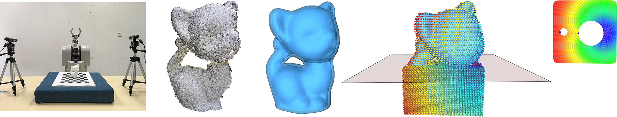
In order to validate our approach on real data, we build a platform with a 7-DoF Barrett WAM arm, a Barrett BH8-282 three-finger gripper and two Xtion Pro depth cameras. For each object shown in Fig. 9, we keep the depth cameras unchanged while rotating the target shape repeatedly for times. In this way, we recorded of the grasp success rates. A grasp is regarded to be successful if the target shape does not escape from the gripper during a large-scale movement that is about cm off the ground. We report the success rate of grasping in Table 1. It shows that our approach can synthesize reliable caging grasps, as compared to traditional approaches whose success rate is generally about .
5.4 Performance
In order to accomplish a grasping task, we have to perform a sequence of shape analysis operations and then send a grasp instruction to the robot. Recall that we define a grasping space and search the best caging loop in that space. In our implementation, we discreticize the bounding box enclosing the target shape into voxels and label each voxel between the -offset surface and its convex hull with “1”. After that, we extract a set of uniformly distributed sample points from and eliminate those sample points that do not help determine a caging loop at all (see Theorem 3.3). Finally, the loop candidate pool is generated based on Morse theory. Among these steps, the most time-consuming steps include the grasping space computation, a distance field generation for a collection of base points and topological analysis based on Morse theory. The mesh models shown in this paper are discretized into 2K vertices, and the average computation time for each model is about 1.5 seconds. It can be seen that our algorithm runs very fast at this level of resolution. Therefore, if we simultaneously execute the computation task and the move of gripper, it does not introduce a noticeable delay.
6 Conclusion and Discussion
In this work, we propose to synthesize feasible caging grasps in the shape embedding space of the target object. Our caging loops are able to encompass multiple small topological handles and concave regions, which are relatively too small to be grasped, through decoupling their computation from surface geometry of the target object. This also facilitates grasp synthesis for unknown objects which are acquired and reconstructed on-the-fly. Extensive experimental results exhibit that our approach can deal with real objects with complex surface geometry and topology, being aware of the relative size between objects and gripper.
Our current solution has several limitations. First, the method used for measuring the physical feasibility is merely a preliminary solution which can definitely be replaced by other alternatives. Our core method for caging loop computation, however, ensures the candidate loops are mostly feasible with respect to the gripper size. Second, the caging loops computed by our method mainly reflect the geometric aspect of graspability and do not account for the high level information of semantics or functionality. For example, an object can be grasped in different ways for different purposes. Synthesizing function related grasps is an interesting venue for future study.
References
- [1] A. Rodriguez, M. T. Mason, and S. Ferry, “From caging to grasping,” I. J. Robotics Res., vol. 31, pp. 886–900, 2011.
- [2] W. Wan, R. Fukui, M. Shimosaka, T. Sato, and Y. Kuniyoshi, “A new ‘grasping by caging’ solution by using eigen-shapes and space mapping,” in ICRA, 2013.
- [3] R. Diankov, S. S. Srinivasa, D. Ferguson, and J. J. Kuffner, “Manipulation planning with caging grasps,” in Humanoids, 2008.
- [4] X. Zhu and H. Ding, “Planning force-closure grasps on 3-D objects,” in ICRA, 2004.
- [5] D. Ding, Y. Liu, and S. Wang, “Computing 3-D optimal form-closure grasps,” in ICRA, 2000.
- [6] C. Borst, M. Fischer, and G. Hirzinger, “Grasping the dice by dicing the grasp,” in IROS, 2003.
- [7] C. Ferrari and J. F. Canny, “Planning optimal grasps,” in ICRA, 1992.
- [8] D. Zarubin, F. T. Pokorny, M. Toussaint, and D. Kragic, “Caging complex objects with geodesic balls,” 2013 IEEE/RSJ International Conference on Intelligent Robots and Systems, pp. 2999–3006, 2013.
- [9] F. T. Pokorny, J. A. Stork, and D. Kragic, “Grasping objects with holes: A topological approach,” 2013 IEEE International Conference on Robotics and Automation, pp. 1100–1107, 2013.
- [10] T.-H. Kwok, W. Wan, J. Pan, C. C. L. Wang, J. Yuan, K. Harada, and Y. Chen, “Rope caging and grasping,” 2016 IEEE International Conference on Robotics and Automation (ICRA), pp. 1980–1986, 2016.
- [11] R. A. Newcombe, S. Izadi, O. Hilliges, D. Molyneaux, D. Kim, A. J. Davison, P. Kohli, J. Shotton, S. Hodges, and A. W. Fitzgibbon, “Kinectfusion: Real-time dense surface mapping and tracking,” in ISMAR, 2011.
- [12] A. Bicchi, “On the closure properties of robotic grasping,” I. J. Robotics Res., vol. 14, pp. 319–334, 1995.
- [13] A. T. Miller and P. K. Allen, “Graspit! a versatile simulator for robotic grasping,” IEEE Robotics and Automation Magazine, vol. 11, pp. 110–122, 2004.
- [14] Y. Liu, “Qualitative test and force optimization of 3-D frictional form-closure grasps using linear programming,” IEEE Trans. Robotics and Automation, vol. 15, pp. 163–173, 1999.
- [15] W. S. Howard and V. Kumar, “On the stability of grasped objects,” IEEE Trans. Robotics and Automation, vol. 12, pp. 904–917, 1996.
- [16] E. Rimon and A. Blake, “Caging planar bodies by one-parameter two-fingered gripping systems,” I. J. Robotics Res., vol. 18, pp. 299–318, 1999.
- [17] P. Pipattanasomporn and A. Sudsang, “Two-finger caging of concave polygon,” Proceedings 2006 IEEE International Conference on Robotics and Automation, 2006. ICRA 2006., pp. 2137–2142, 2006.
- [18] ——, “Two-finger caging of nonconvex polytopes,” IEEE Transactions on Robotics, vol. 27, pp. 324–333, 2011.
- [19] M. Vahedi and A. F. van der Stappen, “Caging convex polygons with three fingers,” 2008 IEEE/RSJ International Conference on Intelligent Robots and Systems, pp. 1777–1783, 2008.
- [20] T. K. Dey, J. Sun, and Y. Wang, “Approximating loops in a shortest homology basis from point data,” in Symposium on Computational Geometry, 2010.
- [21] J. A. Stork, F. T. Pokorny, and D. Kragic, “Integrated motion and clasp planning with virtual linking,” 2013 IEEE/RSJ International Conference on Intelligent Robots and Systems, pp. 3007–3014, 2013.
- [22] P.-T. Bremer, H. Edelsbrunner, B. Hamann, and V. Pascucci, “A topological hierarchy for functions on triangulated surfaces,” IEEE Transactions on Visualization and Computer Graphics, vol. 10, pp. 385–396, 2004.
- [23] X. Ni, M. Garland, and J. C. Hart, “Fair Morse functions for extracting the topological structure of a surface mesh,” ACM Trans. Graph., vol. 23, pp. 613–622, 2004.
- [24] L. Lusternik and L. Schnirelmann, Méthodes topologiques dans les problèmes variationnels. Hermann, 1934.
- [25] J. C. Carr, R. K. Beatson, J. B. Cherrie, T. J. Mitchell, W. R. Fright, B. C. McCallum, and T. R. Evans, “Reconstruction and representation of 3D objects with radial basis functions,” in SIGGRAPH, 2001.
- [26] A. Varava, D. Kragic, and F. T. Pokorny, “Caging grasps of rigid and partially deformable 3-D objects with double fork and neck features,” IEEE Transactions on Robotics, vol. 32, pp. 1479–1497, 2016.