Multirate 5G Downlink Performance Comparison for f-OFDM and w-OFDM Schemes with Different Numerologies ††thanks: Marina Mondin is also affiliated with DET, Politecnico di Torino, C.so Duca degli Abruzzi 24, 10129, Torino, Italy (marina.mondin@polito.it).
Abstract
One of the main open problems for next generation wireless networks, is to find the new OFDM-based waveform to be used in 5G. The new modulation scheme must primarily be able to achieve higher spectral efficiency than its predecessor. The main 3GPP’s candidate is a new version of OFDM, called Filtered Orthogonal Frequency-Division Multiplexing (f-OFDM), which is similar to OFDM but with additional filtering in order to reduce Out-Of-Band (OOB) emissions and to obtain a better spectral-localization. Another option is windowed-OFDM (w-OFDM), which is basically a classical OFDM scheme where each symbol is windowed and overlapped in the time domain. In this paper we compare classic OFDM signals using Cyclic Prefix (CP-OFDM) with f-OFDM and w-OFDM, each one with multiple parametric options and numerologies. A multirate transmitter simultaneously operating with multiple numerologies is considered, where the transmitted sub-bands must be up-sampled and interpolated in order to generate the composite numerical signal fed to the Digital to Analog Converter (DAC). Finally, we discuss advantages and disadvantages of the various schemes.
Index Terms:
5G, f-OFDM, w-OFDM, CP-OFDMI Introduction
Next generation cellular networks present extremely challenging issues for researchers and engineers. The main goal is to improve the actual LTE performance, in order to meet the growing data demand from the newly provisioned technologies and services. For example, increasing the data rate by a factor 100 with respect to LTE, while decreasing the latency from the actual 15 ms down to as low as approximately, 1 ms. Requirements and key features of 5G are fully presented in [1], [2], [3] and [4]. The new services foreseen in 5G and their associated requirements can be summarized as follows:
-
•
URLLC (Ultra Reliable Low Latency Communications): requires low latency and high reliability;
-
•
eMBB (Enhanced Mobile Broadband): requires low latency, high spectral efficiency and high data rate;
-
•
mMTC (massive Machine Type Communication): requires low energy consumption, low device complexity and an improved link budget.
Enabling new technologies, such as massive MIMO, Device-to-Device communications (D2D), Wireless Software Defined Networking (WSDN), Millimeter Wave communications and network Densification, are being utilized in order to reach 5G’s goals.
In this paper we deal with problems regarding Radio Access techniques. As stated earlier, new services in 5G require high data rates and large spectral efficiency. For this reason, we focus on spectral efficiency problem of a legacy OFDM (Orthogonal Frequency-Division Multiplexing) system, which has to improve its performance to achieve the required targets. As is well known, OFDM is one of the most important transmission techniques of the recent past [5], largely used in LTE standards. The principle of OFDM based on sub-carrier division has been well studied and tested during the years and the first advantage of this scheme is its simplicity of implementation. Moreover, OFDM allows for simple modulation and demodulation and is MIMO friendly. On the other hand, OFDM suffers from high PAPR (Peak-to-Average Power Ratio) and, mostly, of high Out-Of-Band (OOB) emissions. The required Cyclic Prefix (CP) and strict bounds for synchronization are among other disadvantages of OFDM. Indeed, in a 5G scenario it is desirable to use sub-bands that do not need to be perfectly synchronized with each other due to the different requirements of the multitude of devices or services on the network. In fact, in 5G we will have different kind of devices which rarely connect to the network. For example, an IoT (Internet of Things) device needs to send just few control bytes on rare occasions, and several kind of devices will have very short battery life. For these reasons, it may be desirable to use a waveform with relaxed synchronization requirements.
This article attempts to summarize benefits and disadvantages of the two schemes currently being considered by 3GPP (Third Generation Partnership Project) for 5G applications, namely f-OFDM (Filtered OFDM) and w-OFDM (Windowed OFDM), and to compare them with classic CP-OFDM. In the last case, we consider standard OFDM sub-bands, without using any strategy to reduce OOB emissions.
In the f-OFDM schemes we use low-pass filters in order to attenuate the OOB emissions and have an efficient sub-band divided system, as explained in [6], [7] and [8], while, in the w-OFDM scenario, OOB emissions are reduced by smoothing the symbol transitions with a time domain window applied on each sub-band, according to [9] and [10]. Other results on f-OFDM can be found in [11] which gives a closed form for ISI (Inter-Symbol Interference), ICI (Inter-Carrier Interference) and ACI (Adjacent-Channel Interference). [12] suggests a filter-bank version of f-OFDM, while [13] discusses PAPR reduction in f-OFDM. Finally, [14] and [15], describe field trials results for f-OFDM and w-OFDM based systems in real environments.
In contrast to previous studies, our comparison is made for a realistic multirate transmitter able to simultaneously transmit sub-bands with different numerologies, where the signals associated with the low-rate sub-bands must be up-sampled and interpolated in order to generate the composite numerical signal fed to the DAC. As a consequence, our results also account for the effects generated by up-sampling and interpolation.
The remainder of this paper is organized as follows. In section II we present our framework and show the generic structure of the considered Base Station (BS) transmitter. In subsections II-A, II-B and II-C, we give details on the considered signal waveforms, and in the section III we describe the receiver structure. Finally, in section IV we show different simulation results to evaluate and compare our waveforms, and finally present the conclusions in section V.
II Transmitter structure
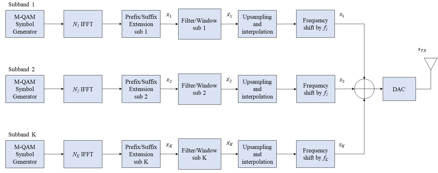
In this section we provide a full description of our three proposed schemes, we start by showing the common elements and then detail the specifics of each signal. On the transmitter, we are focusing on a Base Station (BS) scenario, which simultaneously transmits multiple sub-bands with multiple numerologies, followed by a single-sub-band receiver (we are assuming that each service, or user, could be served by more than one sub-band).
Figure 1 shows the BS transmission structure which is common for all the considered waveforms, with differences residing in the prefix/suffix and filter/window blocks. The processing details for the considered schemes are described in sections II-A, II-B and II-C.
The transmission steps are very similar to a classical OFDM scheme, starting with a QAM symbol generator over the branches, where represents the number of sub-bands generated by the BS and it depends on the plurality of services offered by the network. In order to have a fair comparison, we assume to have the same modulation order among all the sub-bands. We will consider M-QAM schemes, with , as suggested by the 3GPP LTE-A standard. These symbols are transmitted on the useful sub-carriers (and possibly on the pilot sub-carriers, that in this study will be treated as useful sub-carriers), while null values are formally transmitted on the (unused) null sub-carriers.
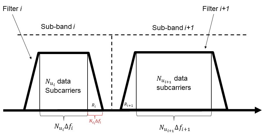
Since we will have different coexisting numerologies, every sub-band may have an FFT/IFFT processor with a different dimension, so we denote by the IFFT dimension used in the sub-band. is typically selected to be a power of 2, so we can write , where is a non-negative integer. Each sub-band could have a different number of useful sub-carriers, so that we have null sub-carriers. Furthermore, represents the total number of ‘’guard” sub-carriers introduced between the sub-band and its neighboring sub-bands. We choose to use sub-carriers on the right and the same number on the left side of our useful sub-carriers. We also denote as the sub-carrier spacing in the sub-band, defined as a power-of-2 multiple of the minimum sub-carrier spacing (equal to ), so that we can write , where is a non-negative integer. Given these assumptions, we can express the sampling frequency used for the sub-band as:
| (1) |
Given these assumptions, the transition guard band between the and sub-band (shown in Figure 2) is equal to .
We also denote as the total bandwidth used for transmission, and as the total bandwidth of the sub-band. With this representation we have and . Obviously, in order to achieve a better spectral efficiency it is desirable to have in order to avoid wasting frequency resources, with a consequential loss in terms of spectral efficiency. In this paper we consider different values of to show their impact on some performance indicator such as the raw-BER.
The prefix/suffix block adds a Cyclic Prefix or Suffix depending on the considered waveform.
Next, with reference to Figure 1, the sequence is either filtered or windowed depending on the considered scheme in order to improve frequency localization and lower the spectral side-lobes.
In order to add the signals associated to sub-bands with different numerologies we have to convert them to a common sampling frequency (possibly the least common multiple frequency) that we achieve by up-sampling the signals sampled at the lower frequencies.
Given our assumptions, the least common multiple frequency is the maximum frequency among all the sub-bands, i.e., from (1)
| (2) |
where, . The upsampling factor for each sub-band is calculated as
| (3) |
Each up-sampled signal needs to be interpolated with a low pass filter (designed as described in II-B) and properly shifted in the frequency domain by frequency in order to generate the composite overall digital sequence, where
| (4) |
and , is the center frequency of the first sub-band. The signals associated to the sub-bands are then added and sent to the DAC.
II-A CP-OFDM
In the case denoted as CP-OFDM, the transmitter implements a classic OFDM scheme with cyclic prefix (without windowing or filtering to reduce OOB emissions). We will consider this scheme as reference against which we compare the other schemes. In this case, the Prefix/Suffix block just adds the Cycling Prefix (CP) containing samples.
II-B Filtered OFDM
The transmission chain for f-OFDM is very similar to that for the CP-OFDM, with an additional low-pass filter introduced after the CP concatenation and before the frequency shift in order to reduce the OOB emissions. Clearly, the structure of the transmitter low-pass filter is very important for reducing OOB emissions and possible interference. Ideally, we want a filter perfectly flat in pass-band and zero outside this band, with null transition bands. This kind of filter is physically unrealizable, but can be approximated by truncating and windowing the ideal impulse response.
This operation introduces a new element in this framework, the filter transition bands. It is important to note that the transition bands are completely independent from frequency guard bands introduced above. Obviously having the transition band contained in the guard band could guarantee better performances.
The filter has to be as flat as possible in the pass-band with tight transition bands. To achieve this goal we have chosen a windowed-sinc filter with ideal impulse response
| (5) |
for where, represents the filter order and the transition band on one side. does not represent our final filter, it is just a truncated . The final coefficients of our normalized lowpass filter are given by
| (6) |
where, the term represents the chosen window. In this paper we use a raised cosine window defined as
| (7) |
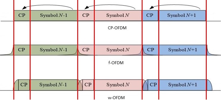
where, is bounded as in equation (5). The filter impulse response contains samples, which causes a signal extension in the time domain by samples. This signal elongation could seem a critical point of the f-OFDM scheme leading to interference in time. Fortunately, this kind of filter has the major part of its energy concentrated in the main Sinc lobe, so the elongation is important just for a small time period during the CP of the successive symbol (see Figure 5). For this reason, it is not strictly necessary to choose to be very small, specifically can be larger than (length of the cyclic prefix).
II-C Windowed OFDM
In this section we illustrate the time domain windowing strategy. Since, the signal high frequency components are mainly generated by the discontinuities between adjacent OFDM symbols, softening these singularities with a smooth transition lowers the OOB emissions. Specifically, the OFDM symbols must be elongated with the insertion of CP, prefix and suffix, then windowed and finally concatenated (by partially overlapping two consecutive symbols).
The first operation is to extend our OFDM symbol by copying the last samples of the native OFDM symbol at the beginning of the new w-OFDM symbol, as typically done for CP-OFDM (II-A). The first samples are denoted as ”prefix”, while the remaining are denoted as CP. The w-OFDM symbol is then further extended by copying the first samples of the native OFDM symbol at the end of the new w-OFDM symbol, as shown in Figure 3.

Native OFDM symbols in each sub-band may have different lengths, hence the parameter is used to denote the prefix/suffix parameter for the sub-band. At this point the w-OFDM symbol that we denote as contains samples. However, prefix and suffix will be smoothed with a windowing operation, and then the suffix of the w-OFDM symbol will be overlapped with the first samples of the w-OFDM symbol.
The windowed symbol is obtained from the extended symbol via
| (8) |
where, represents the chosen window of length . As proposed in [9], we use a window defined via,
| (9) |
where, represents a column vector of elements filled by zeros, likewise is the same kind of vector filled by ones. The parameter represents the window transition length, i.e. the number of samples the window spends to go from zero-to-one and from one-to-zero, and is the transition length in the sub-band. The vector contains the uphill samples of the window, and the downhill samples. These vectors are defined via,
| (10) |
| (11) |
In this paper we chose to use a Blackman windowing function so that,
| (12) |
This completes the explanation of how to build a single w-OFDM symbol. The last of a symbol are then overlapped and added to the first of the successor, as shown in Figure 4. Hence, to obtain the desirable effect of smooth transitions, we must choose the overlapping length to be higher than the transition time . Is important to notice that the w-OFDM symbol is longer than CP-OFDM and f-OFDM symbols. So that, in order to have comparable symbol duration, for our simulations we decide to adopt a different CP duration for w-OFDM, defined as , with . In this configuration the final w-OFDM duration will be , where the last samples are overlapped with the following symbol. Figure 5 shows symbol duration on our three framework.

III Receiver structure

Figure 6 shows the generic structure of the receiver for a the sub-band. The receiver structure is very general and can be adapted to various schemes with minimal modifications.
The first step is the frequency down-conversion,
that generates the baseband version of the signal from which to filter out the sub-band. After filtering, we need to down-sample, eliminate the prefix/suffix and perform a -points FFT.
The low pass filter has to be as flat as possible in our pass-band, with tight transition bands and high stopband attenuation. In this paper we choose to use the same filter used in transmission for the f-OFDM in II-B.
IV Numerical results
In this section we provide the results obtained by numerical simulations of CP-OFDM, f-OFDM and w-OFDM schemes in a three sub-bands environment. Since we are only comparing the robustness of the considered schemes to adjacent channel interference generated by the simultaneous use of different numerologies, we consider a simple AWGN channel, without taking into account transmission effects such as non-linearity or fading, that would affect all the waveforms in the same way. The simulations consider a scenario with sub-bands with the numerologies listed in Table I. In all simulations we chose to use as number of useful data carriers an integer multiple of a PRB (Physical Resource Block), fixed at sub-carriers. In particular we chose to use PRB for each sub-band and for each simulation.
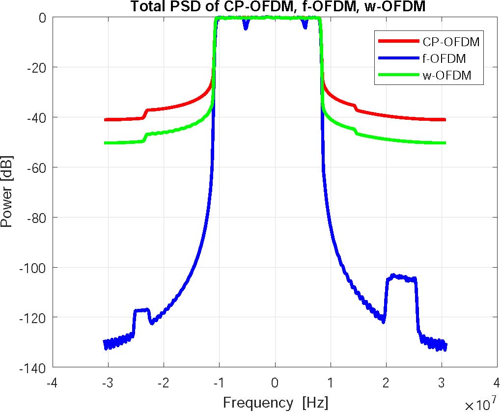
The Power Spectral Density (PSD) of the composite signal containing the three subbands described in Table I is shown Figure 7. The bit-error-rate performances obtained using semi-analytic techniques [16] for QPSK and 256 QAM constellations are reported in Figures 8 and 9, respectively.
| Parameter | Sub-band 1 | Sub-band 2 | Sub-band 3 |
|---|---|---|---|
| 1024 | 1024 | 1024 | |
| 64 | 64 | 64 | |
| 30 | 60 | 15 | |
| 177 | 89 | 353 | |
| (kHz) | 180 | 180 | 180 |
| (kHz) | 90 | 90 | 90 |
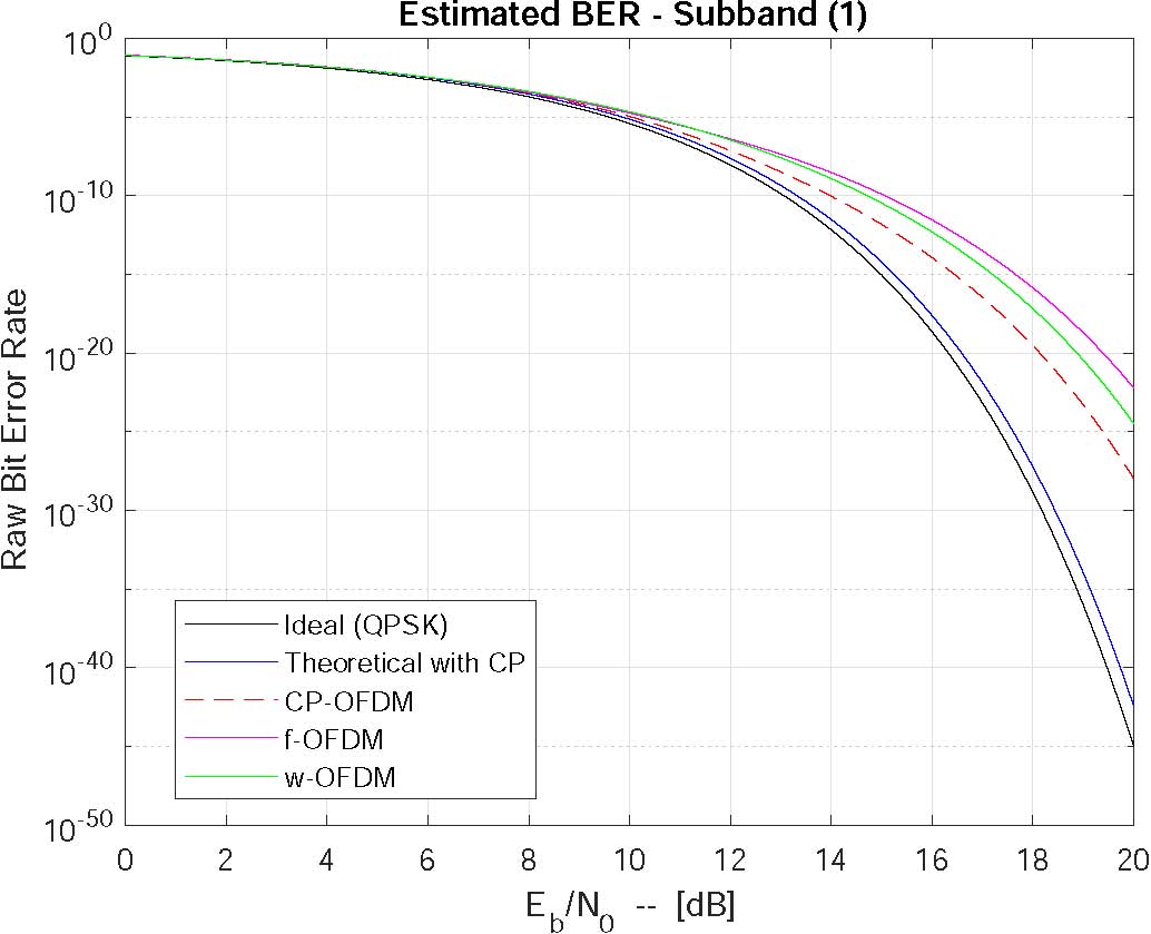
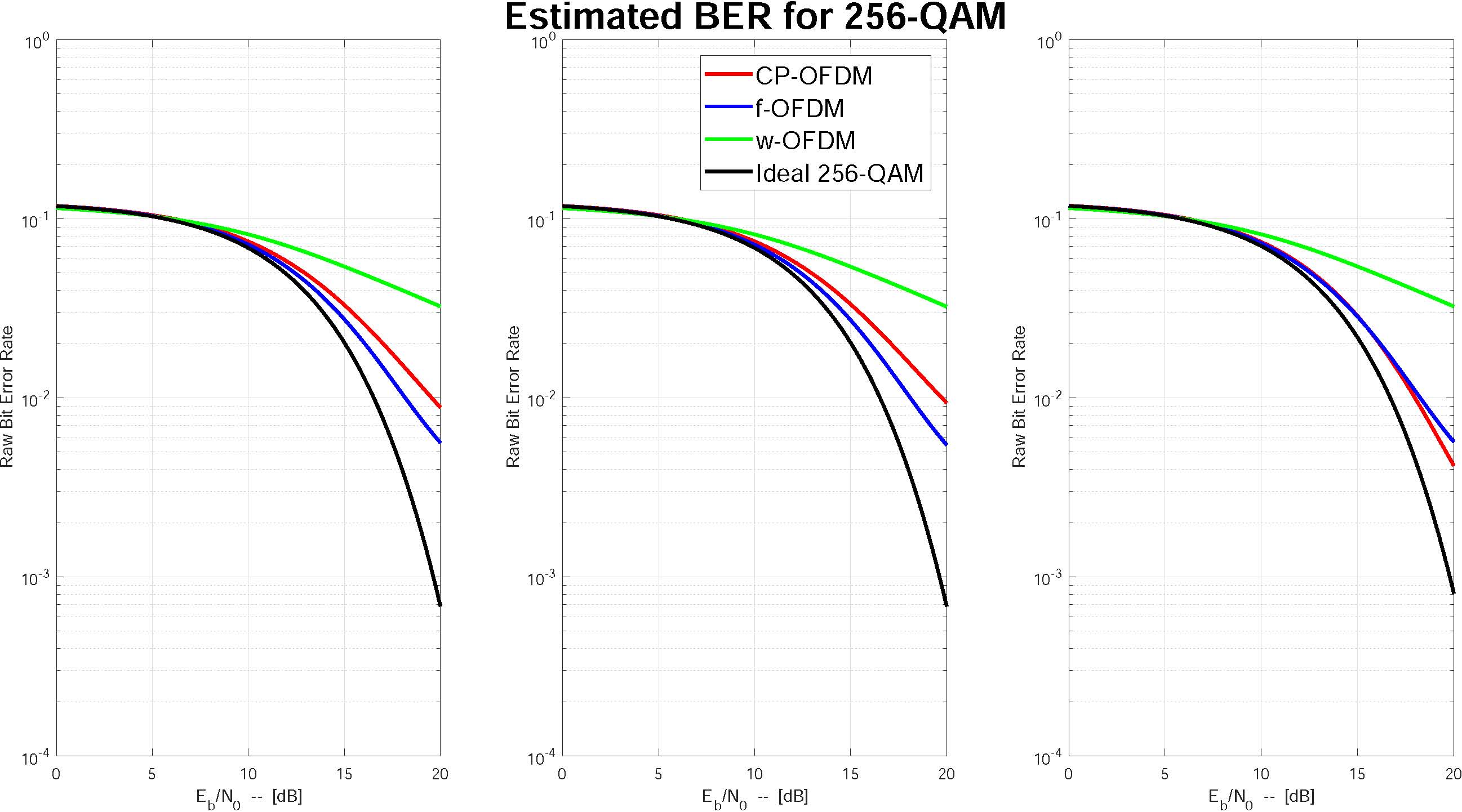
As it can be observed in Figures 9 and 8, when different numerologies are used in adjacent subchannels (introducing ACI, Adjacent Channel Interference, due to the non-orthogonality of the OFDM subcarriers), a loss can be observed on the BER curves that would not be present with a unique numerology (these ideal curves are not reported for brevity). As expected, such loss is more noticeable with higher modulation orders and in subchannels that suffer from higher interference from adjacent subchannels (like subchannel 3, whose higher ACI can be observed in Figure 9).
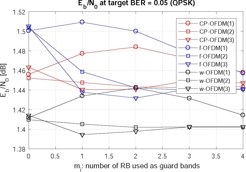
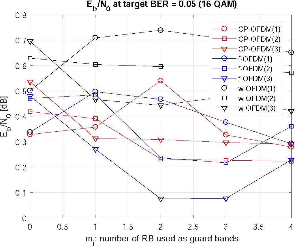
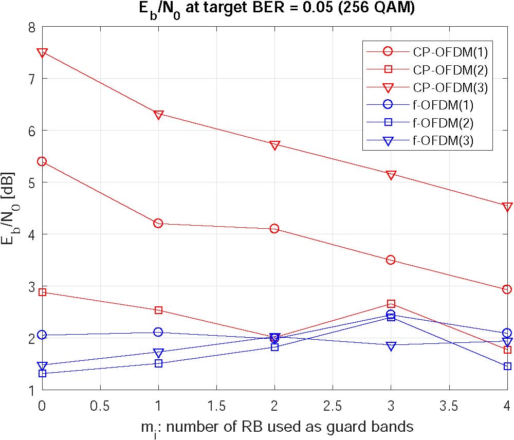
A second set of performance curves has been obtained to show the sensitivity of various schemes to subchannel separation, where we have selected (i.e., the subchannel separation is equal to resource blocks with ) and .
As shown in Figure 10, BER performance improve with subchannel separation and for low modulation orders (QPSK) w-OFDM offers better performances than f-OFDM (in this case, the distortion introduced by filtering on f-OFDM is more relevant than the distortion introduced on w-OFDM by the use of a windowed CP). The situation changes as the modulation order increases (and the effect of ACI becomes more relevant): as shown in Figure 11, CP-OFDM offers the best performance in this scenario for 16QAM (while f-OFDM and w-OFDM are almost comparable), while f-OFDM outperforms the other schemes with a 256QAM modulation as shown in 12 (w-OFDM performance in this case are very bad and are not shown in the graph). Overall we can observe that while w-OFDM outperforms f-OFDM for low modulation orders, f-OFDM offers better performance with high modulation orders. Furthermore, at high modulation orders, the performance of f-OFDM does not significantly degrade as the channel separation decreases, and it is possible to allocate the various subchannels extremely close to each other, thus improving the spectral efficiency.
V Conclusions
In this paper a multirate transmitter simultaneously operating with multiple numerologies has been considered, comparing the performance of the OFDM-based schemes that are currently being considered for 5G applications in a realistic scenario via accurate simulations. Specifically, simulated performances of CP-OFDM, w-OFDM and f-OFDM schemes have been presented showing that while w-OFDM offers better performance with low modulation orders, f-OFDM, thanks to its better OOB attenuation, outperforms both w-OFDM and CP-OFDM with high modulation orders, while offering a reduced sensitivity to subchannel separation.
References
- [1] J. G. Andrews, S. Buzzi, W. Choi, S. V. Hanly, A. Lozano, A. C. Soong, and J. C. Zhang, “What will 5G be?” IEEE Journal on selected areas in communications, vol. 32, no. 6, pp. 1065–1082, 2014.
- [2] I. F. Akyildiz, S. Nie, S.-C. Lin, and M. Chandrasekaran, “5G roadmap: 10 key enabling technologies,” Computer Networks, vol. 106, pp. 17–48, 2016.
- [3] F. Boccardi, R. W. Heath, A. Lozano, T. L. Marzetta, and P. Popovski, “Five disruptive technology directions for 5G,” IEEE Communications Magazine, vol. 52, no. 2, pp. 74–80, 2014.
- [4] E. Hossain and M. Hasan, “5G cellular: key enabling technologies and research challenges,” IEEE Instrumentation & Measurement Magazine, vol. 18, no. 3, pp. 11–21, 2015.
- [5] R. v. Nee and R. Prasad, OFDM for wireless multimedia communications. Artech House, Inc., 2000.
- [6] X. Zhang, M. Jia, L. Chen, J. Ma, and J. Qiu, “Filtered-OFDM-enabler for flexible waveform in the 5th generation cellular networks,” in Global Communications Conference (GLOBECOM). IEEE, 2015, pp. 1–6.
- [7] J. Abdoli, M. Jia, and J. Ma, “Filtered OFDM: A new waveform for future wireless systems,” in Signal Processing Advances in Wireless Communications (SPAWC), 2015 IEEE16th International Workshop on. IEEE, 2015, pp. 66–70.
- [8] J. Li, K. Kearney, E. Bala, and R. Yang, “A resource block based filtered OFDM scheme and performance comparison,” in Telecommunications (ICT), 2013 20th International Conference on. IEEE, 2013, pp. 1–5.
- [9] K. Mizutani and H. Harada, “Universal Time-Domain Windowed OFDM,” in Vehicular Technology Conference (VTC-Fall), 2016 IEEE 84th. IEEE, 2016, pp. 1–5.
- [10] K. Mizutani, Z. Lan, and H. Harada, “Time-domain windowing design for IEEE 802.11 af based TVWS-WLAN systems to suppress out-of-band emission,” IEICE Transactions on Communications, vol. 97, no. 4, pp. 875–885, 2014.
- [11] L. Zhang, A. Ijaz, P. Xiao, M. Molu, and R. Tafazolli, “Filtered OFDM Systems, Algorithms and Performance Analysis for 5G and Beyond.”
- [12] Y. Qiu, Z. Liu, and D. Qu, “Filtered bank based implementation for filtered OFDM,” in 2017 7th IEEE Int. Conf. on Electronics Information and Emergency Communication (ICEIEC). IEEE, 2017, pp. 15–18.
- [13] M. B. Mabrouk, M. Chafii, Y. Louet, and C. F. Bader, “A Precoding-based PAPR Reduction Technique for UF-OFDM and Filtered-OFDM Modulations in 5G Systems,” in European Wireless 2017, 2017.
- [14] D. Wu, X. Zhang, J. Qiu, L. Gu, Y. Saito, A. Benjebbour, and Y. Kishiyama, “A field trial of f-OFDM toward 5G,” in Globecom Workshops (GC Wkshps), 2016 IEEE. IEEE, 2016, pp. 1–6.
- [15] P. Guan, D. Wu, T. Tian, J. Zhou, X. Zhang, L. Gu, A. Benjebbour, M. Iwabuchi, and Y. Kishiyama, “5G Field Trials: OFDM-Based Waveforms and Mixed Numerologies,” IEEE Journal on Selected Areas in Communications, vol. 35, no. 6, pp. 1234–1243, 2017.
- [16] K. S. S. Michel C. Jeruchim, Philip Balaban, Simulation of Communication Systems: Modeling, Methodology and Techniques. Springer US, 2000.
