[para]default
G
en
oM3 Templates: from Middleware Independence to
Formal Models Synthesis
††thanks: This work was supported in part by the EU CPSE Labs project funded by the H2020 program under grant agreement No 644400.
Abstract
G en oM is an approach to develop robotic software components, which can be controlled, and assembled to build complex applications. Its latest version G en oM3, provides a template mechanism which is versatile enough to deploy components for different middleware without any change in the specification and user code. But this same template mechanism also enables us to automatically synthesize formal models (for two Validation and Verification frameworks) of the final components. We illustrate our approach on a real deployed example of a drone flight controller for which we prove offline real-time properties, and an outdoor robot for which we synthesize a controller to perform runtime verification.
1 Introduction
There is a rising concern in advanced robotic and autonomous systems software development. Can we improve the dependability of such systems by deploying formal validation and verification (V&V) techniques applied to their software? Such techniques are widespread in areas such as aeronautic, railway, etc, but are still seldom used in robotics. Nowadays, robotic software developments use model-based or model-driven software engineering approaches (e.g. SmartSoft [1], RobotML [2], MontiArc [3]). These approaches and their associated middleware are numerous and surveyed in a number of papers [4, 5, 6]. Still, most of theses approaches remain disconnected to formal model analysis and the use of V&V techniques. Several works proposed to use the formal synchronous language ESTEREL [7] to model functional components [8, 9, 10]. The formal models were then exploited to verify behavioral and timed properties using model checking tools. These experiments were nevertheless led on simple examples and specifications were either hard-coded in ESTEREL or manually translated from robotic components. More recently a special issue [11] on this subject presented a number of interesting works along hybrid automata [12] and controller synthesis [13] and more recently [14]. The formal frameworks proposed are similar to the ones we use, but they are mostly deployed at decisional level or on rather simple robotic systems. Our approach is somewhat complementary in choosing to model all the software components which need to be integrated together at the functional level and then checking and enforcing properties on the integrated code. The closest work to our approach is MAUVE [15], where the code is instrumented to collect Worst Case Execution Time (WCET), and then temporal formal property can then be checked on the components. Our approach distinguishes itself by, simultaneously, being fully automatic, considering all timing constraints of the model and tackling rather complex integrated robotic applications.
In this paper we present the G en oM3 framework to specify and deploy robotic functional components. G en oM3 relies on a specification language which allows the programmer to completely define how the component will work when associated to the user provided code, and how this code will be internally organized along services, tasks, ports, etc. This specification is done independently of the middleware targeted and, thanks to its template mechanism, can also be used to synthesize more than just the final code of the component, but also client libraries, and models for various V&V frameworks.
The paper first describes, with an example, the specification language used by G en oM3. Section 3 presents the template mechanism used to synthesize middleware specific components, but also to produce the components formal models for two V&V frameworks. Section 4 briefly presents two examples (a drone flight controller and an outdoor robot navigation) which have been completely specified in G en oM3, followed by a section where we illustrate the type of properties we can formally prove on the resulting models, as well as how we synthesize a runtime controller to run the component. The paper concludes on the ongoing work along these lines and the future extensions we intend to tackle.
2 G en oM3 components
G en oM3 [16] is a tool to specify and implement robotic functional components. In the overall LAAS architecture [17], functional components act as “servers” in charge of functionalities which may range from simple low-level driver control (e.g. the velocity control of the propellers of a drone, camera, etc) to more integrated computations (e.g. Simultaneous Localization And Mapping (SLAM), navigation, PRM or RRT motion planning, etc).
2.1 Requirements
We consider that a typical component is a program which needs to handle and manage the following aspects:
- Inputs and Outputs
-
: a component interacts with external clients and other components. For the former, the control flow, it must handle requests from client(s) and asynchronously send back reports to the client which issued the request, to act on the result. For the latter, the data flow, it must provide a mechanism to share data with other components and read data from other components. Data flow and control flow are semantically different and correspond to two different ways components can interact.
- Algorithms
-
: the core algorithms needed to implement the functionality the component is in charge of must be appropriately organized within threads as to preserve the reactivity of the component and the schedulability of the various possibly concurrent algorithms. A component may have just one service to provide, but most of the time, there are a number of such services associated to the considered robotic functionality. The way algorithms are specified and organized in a component is a tradeoff. One can let the programmer organize its code the way it pleases him. But without any particular structure, chances are that little can be validated or verified. If one provides guidelines and rules as how the code must be organized, than we stand a much better chance as to prove some properties on the code.
- Internally shared data
-
: the various algorithms, possibly concurrent, running in the component, may have to share state variables, parameters, etc. which represent the internal state of the component.
2.2 Implementation
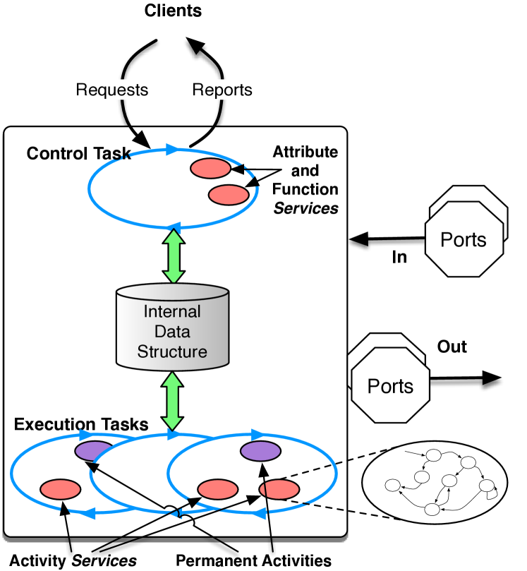
To achieve such requirements of a functional component, we propose to organize each one along the structure shown on Fig. 1. Of course, the pros and cons of these implementation choices can be discussed, and we will attempt to justify them as we present them. We illustrate the detailed specifications on Listing 1, with the maneuver component of the complete functional layer of a Mikrokopter drone flying in our lab (Fig. 2). This component, given a position to hoover or waypoints to pass by, is in charge of producing intermediate positions to navigate to.
Specifying a component in G en oM3 is the programmer design choice. Thus, there are a number of considerations she/he has to take into account, which may depend on the hardware constraints, the complexity of the algorithm, the needed external data, etc. Let us describe these different elements in more details and how they interact, and how they are specified. Note that at this point, we are not assuming any particular middleware for interprocess communication or data sharing (control and data flow).
Apart from the control task, each element of the specification results from choices the developper has to carefully make (how many tasks? periodic or not? if periodic, which period? which services associated to which task? how to break down long services in processing steps? etc):
- Control Task
-
: A component always has a control task that manages the control flow by processing requests and sending reports (from/to external clients); activate and stop services, etc. The control task is implicitly comprised within a component and the user does not need to specify it.
- Execution Task(s)
-
: Aside from the control task, whose reactivity must remain short, one may need one or more execution tasks, aperiodic or periodic, in charge of longer computations.
- Services
-
: The core algorithms needed to implement the functionality the component is in charge of are encapsulated within services. Services are associated to a request (with the same name), but one may also define permanent activities which are attached to an execution task.
- IDS
-
: A local internal data structure is provided for all the services to share parameters, computed values or state variables of the component. It is appropriately accessed (i.e. with proper locking) by the services when they need to read or write a field of the IDS (line 10).
- Ports
-
: They specify the shared data, in and out, the component needs or produces from/for other components (line 3).
- Exceptions
-
: One may specify exceptions, which can be returned by services to report non nominal execution (line 7).
We go in more details and see how these different elements interact and how the component internally runs.
Services
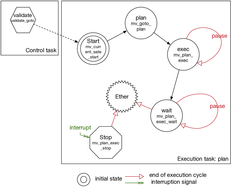
Services hold the specifications of the algorithms handled by the component. Services can take arguments (line 35), and return values (line 29). Services are activated upon receiving the corresponding request. A service may have a validate codel (line 38). This codel is executed by the control task and checks that the arguments of the request are correct. If they are, the service is then runnable, otherwise, it is reported with an illegal arguments report. A service may also specify other services it interrupts (line 45) when it becomes runnable. The interrupted services execute a stop codel (line 43) if any and report to their client that they have been interrupted.
Control Services, are only for short execution as to not delay the control task which executes them. A control service may be an attribute (setter or getter of fields of the IDS, line 27), or a function (line 29) for quick and simple computations. A G en oM3 component offers four predefined function services, namely: Kill (stop the component), Abort (stop an activity service), Connect Port to connect a local in port to a distant out port and Connect Service to connect a service of another component.
Activity services (activities for short), see line 35 and 47, are executed in the execution task specified in their declaration (line 37). They all have a start codel which is the entry point of their codels finite-state machine (FSM) and as many states/codels, as the programmer wants, to specify the decomposition of the long computation they are performing (e.g., the FSM defined from line 39 to 43, also drawn on Fig. 3). The execution of a codel always returns the next state to which the execution must transition to in the service FSM. If the returned state is prefixed with pause (line 41), the control of the execution task is passed to the next service to execute in this task, if any, or back to the scheduler as to wait until the next task period. ether is a special state to which a terminating service can transition. An activity may be permanent (from line 21 to 24). It is not requested by a client and is run by its execution task when the component starts.
Codels specify the C or C++ function they will call, with the arguments (taken from the service arguments, the IDS and/or the ports of the component) they need (in and out). Codels are restricted to use these arguments only. Codels are also restricted to return a state/codel specified in the FSM definition of their service. Each codel may specify a WCET, which measures the worst case execution time of the codel alone (i.e., executing independently of any other execution). The organisation of activity services along FSM and codels may be seen as an unnecessary burden on the robot programmer, but nothing prevent the programmer to have one start codel which does it all. Yet, breaking code along a FSM brings a number of advantages when it comes to better code integration and V&V. It improves schedulability and code execution interleaving. It provides a finer model of data sharing and code interlocking.
Control Task
As seen before, the control task manages the requests and reports of the component, as well as starting, terminanting services. It runs the validate codels for services which specify one. If there exist activities that are incompatible with the requested service, the control task instructs the execution tasks in charge of such activities to interrupt them. If the request concerns a control service (attribute, line 27 or function, line 29), the control task executes it directly. Otherwise, the requested activity service is then put on hold until all the incompatible instances are correctly interrupted and terminated. Then the control task advises the execution task declared by the service to run it, and sends an intermediate reply to the client to inform it that processing has started. Upon completion of services, the control task sends reports to the corresponding client (service ended nominally, service interrupted, etc.).
Execution Tasks
Execution tasks are periodic (with a specified period, line 20) or aperiodic (line 15). With each period signal (if periodic) or event occurrence (if sporadic), the execution task runs its permanent activity (if any) and then all the active instances of its associated activities. An active instance of a given activity is an instance that has been requested by a client and whose execution has not yet ended.
Internal Data Structure
Access to the IDS is mutually exclusive. One can see that the proper specifications (enforced by G en oM3) of the codel arguments allows for a very fine grain locking of the IDS field. In other words, we know at any time which codels access what. Only the needed field(s) by a codel are locked in order to ensure maximal parallelism.
Ports
Information exchange with other components is made through ports (line 3). As seen above, ports usage (in, out or in/out) is also declared in codels arguments. As such, over a large set of components composing a robotic functional layer, we have a clear model of which codels use a particular port and at what time.
3 Templates Approach
As seen above, G en oM3 provides a rich language to specify functional components and how they should be organized. Still, producing the real component code to run on the robot, out of this specification, requires additional steps. This is where G en oM3 template mechanism is critical. G en oM3 without template just analyzes the specification file and checks it for inconsistencies. The real power of G en oM3 is to call it on a specification file, along with a template, as to automatically synthesize the target of the template.
A template when called by G
en
oM3 on a given component specification has access to all the information contained in the specification file
such as services names and types, ports and IDS fields needed by each codel, execution tasks periods, etc. Based on all these specifications,
G
en
oM3 can also compute information such as which codels can execute at the same time (considering their respective arguments), or which
port must be locked by which codel. etc.
Through the template interpreter
(Tcl), one specifies what they need the template to synthesize. Since the interpreter relies on a complete scripting language, there is
virtually no restriction on what a template can generate. For instance, Listing 2 shows an excerpt of a template function and
Listing 3 the C code it produces when called together with the maneuver specification. The interpreter evaluates
anything enclosed in markers ’ ’ without output, while on the code between ” ”,
variables and commands substitution is performed and the result is output in the destination file, together with the text outside of the markers. For example,
<’foreach s [$component services] {’>... <’}’>
iterates over the list of services of the component, contained in the $component variable; while <"[$s name]"> is replaced by
the name of the service contained in the $s variable bound by the foreach statement.
There are a number of templates already defined, to synthesize the component code for a given middleware (e.g., PocoLibs111https://git.openrobots.org/projects/pocolibs, ROS [18]), C client libraries, OpenPRS client procedures and code, a JSON client, etc. For example, the template skeleton generates the files containing the codel stubs with their proper function prototypes. The user can then specify the algorithmic core of their codels without worrying about the middleware.
3.1 Middleware Independence
The middleware “server” templates are used to synthesize the component itself to be run on the robot. They output the glue code in charge of making calls to the targeted middleware. The synthesized glue code manages message passing (requests/reports) as well as ports connection, and handles all the internal algorithms to manage the different tasks, services FSMs, proper locking of shared resources, etc. This is a viable solution to the problem of middleware dependency as neither the specification nor the codels rely on a specific middleware. Indeed, codel execution can only rely on the objects declared in their arg list (i.e. IDS fields, their service arguments and ports) and do not make calls to the middleware.
So far, G en oM3 offers several middleware templates, notably ROS-Com and PocoLibs. The former heavily uses ROS topics, ROS services and ROS actions (actionLib) in the synthesized code, while the latter uses PocoLibs primitives, such as MBox, CSMBox, posters, etc. But from an external behavior point of view, the two resulting components (ROS and PocoLibs) behave exactly the same (apart from performance issues specific to the middleware implementation).
3.2 Formal Verification
G en oM started as a robotic software development tool and methodology in the mid 90’s [19]. Quickly, it appeared that the component specification could be used for more than components code synthesis. An earlier study, using G en oM2, did an ad hoc job at synthesizing a BIP [20] model and went as far as running the synthesized model of 14 components along with the BIP Engine on a real robot [21]. G en oM3 has a semantically cleaner specification model (arbitrarily complex user-defined FSMs, codels WCETs, etc) and thanks to its versatile template mechanism can now be used to synthesize formal models for different frameworks (Fiacre [22] and Real-Time BIP (RT-BIP) [23]). But one should keep in mind that we want to synthesize the model which is semantically equivalent to the resulting component. So the synthesized model goes beyond what is in the component specification file. As a result, the Fiacre or RT-BIP templates synthesize models relative to a targeted specific middleware. Moreover, unlike the previous work presented in [21], the current G en oM3 component specifications include some temporal information: WCET on codels, as well as the period of execution tasks. WCET can be obtained empirically, or with more advanced techniques [24], for now, we get them by running the components and collecting data. Yet, these temporal information were not taken into account in [21] but are now part of the formal models we synthesize.
In [25], a template is presented which automatically synthesizes models in Fiacre [22], a formal language for specifying concurrent and real-time systems based on automata (behavior) and time Petri nets (timing aspects). The synthesized models are exploited in order to verify important real-time properties using TINA [26] model checkers.
G en oM3 also provides a template to automatically generate RT-BIP [20] models. RT-BIP is a formal framework based on interacting components encapsulating timed automata with urgencies. It is associated to an execution engine and an offline deductive verification tool: RTD-finder [27]. The latest release of the RT-BIP engine (RT-BIPE) implements external transitions guarded with external, non controllable events. This allowed us to run the generated models with the RT-BIPE checking for client requests while properly handling the execution of sporadic tasks, particularly the control task, and monitor our components online.
4 Deployed Examples
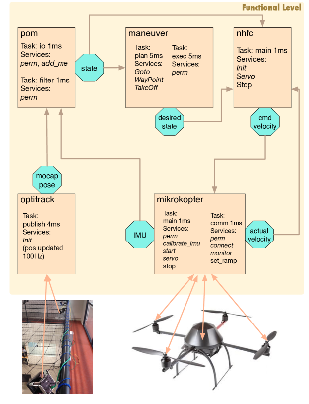
There are already a number of experiments deployed with G en oM3. We illustrate our approach with the functional level of (i) a MikroKopter quadcopter flying in our lab and (ii) our outdoor robot Mana.
4.1 Quadcopter Flying Example
Fig. 2 presents the 5 components involved in our quadcopter functional layer. Each box corresponds to a component, and each octagon is a port. Ports are written (out) by the components they are attached to, and read (in) through the arrow pointing to the reading component. Inside each box, we list the execution tasks (their period or “ap” if they are aperiodic), and a partial list of the services provided by this component. Note that this figure does not present the “supervisor” in charge of sending requests and analyzing reports, which is out of scope of this paper.
-
•
mikrokopter is the component in charge of the quadcopter low-level hardware. The quadcopter is controlled by applying a velocity to each propeller, and produces the current velocities, as well as its current IMU (Inertia Measurement Unit) values. It has two tasks i) comm, aperiodic, which keeps polling and parsing data from the hardware (to get the current propellers velocity and IMU) and storing them in the IDS. ii) main, periodic at 1ms, which reads the cmd velocity port, manages the servo control and writes the two ports IMU and the propellers actual velocity.
-
•
optitrack is the component handling the current position of the quadcopter as perceived by our “OptiTrack” motion capture system. It has one task publish, periodic at 250Hz. It provides the current position of the quadcopter in the mocap pose port.
-
•
pom merges the mocap pose position produced by optitrack and the IMU from mikrokopter and produces an Unscented Kalman filtered position in port state. It has two tasks io and filter both periodic at 1KHz.
-
•
maneuver is the navigation component, it has two tasks exec with a period of 5ms and plan aperiodic. Given a position or waypoints to navigate to, it reads the state, and computes a trajectory to reach it, producing intermediate positions to fly to in desired state.
-
•
nhfc (Near Hovering Flight Controller) is the core of the flight controller. Running one task main at 1KHz, it reads the actual velocity port of the propellers, the current position in the state port of pom, and the desired position (port desired state) of maneuver and produces the proper cmd velocity port containing the desired velocity of the propellers (which is then read by mikrokopter) to reach and hover near this position.
The complexity of our quadcopter functional level is such that with 5 components, 13 tasks running potentially in parallel, over 40 services and more than 65 codels, checking by hand any temporal property is impossible. Note that for the sake of simplicity, only a partial list of services is presented in this paper, we refer the reader to the source repository for the complete specifications https://git.openrobots.org/projects/telekyb3 (in the corresponding sub-projects).
4.2 Outdoor Navigation Example
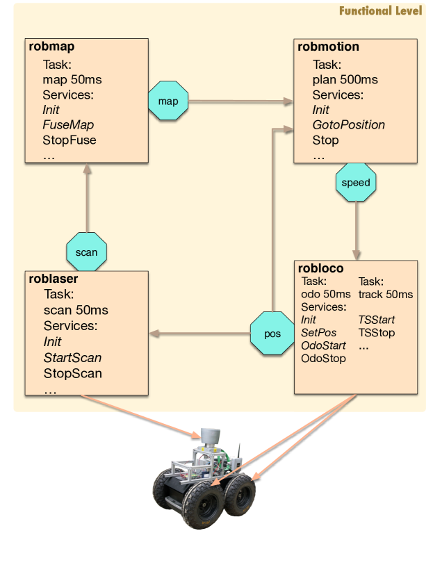
This navigation stack is inspired from the real navigation running on our Segway RMP 400 robot, Mana.
Fig. 4 presents the four components in charge of the navigation:
-
•
robloco is in charge of the robot low-level controller. It has a track task (period 50 ms) associated to the activity TSStart (TrackSpeedStart, interruptible by the function TSStop) that reads data from the speed port and sends it to the motor controller. In parallel, one of the odo task (period 50 ms) associated activities, namely OdoStart (interruptible by the function OdoStop), reads the encoders on the wheels and produces a current position on the pos port.
-
•
roblaser is in charge of the laser. It has a scan task (period 50 ms) which runs the StartScan activity (interruptible by the function StopScan). StartScan produces, on the port scan, the free space in the laser’s range tagged with the position where the scan has been made (read on pos).
-
•
robmap aggregates the successive scan data in the map port. A fuse task (period 50 ms) and FuseMap, one of its activities, perform the computation. The function FuseStop interrupts the activity FuseMap.
-
•
robmotion has one task plan (period 500 ms) which, given a goal position (via the activity GotoPosition), computes the appropriate speed to reach it and writes it on speed, using the current position (from pos), and avoiding obstacles (from map). GotoPosition interrupts itself, so a new request will cancel the currently running one (if it exists) and force the execution of its stop state. Similarly, The Stop service (function) interrupts GotoPosition.
5 Offline and Runtime Verification
Templates are used to generate our quadcopter and outdoor robot components for various middleware. We use these components today routinely on PocoLibs and ROS-Com middleware. In this section, we focus on verification of the PocoLibs implementation as it is more adapted for real-time applications such as flight control running at 1KHz.
5.1 Offline Real-time Properties with Fiacre
When it comes to prove real-time properties on concurrent real-time systems, one has to take into account the hardware on which it runs, and the scheduling policy used. The latest release of the Fiacre template allows the user to provide the number of cores provided by the platform. The template consequently generates a Fiacre model of the components including a cooperative (non-preemptive) FIFO scheduler in charge of allocating the cores to the different tasks present in the components model222In other words, the tasks are not preempted, and release their core/CPU at the end of each cycle.. We give hereafter two examples of real-time properties that we successfully prove on our, respectively, quadcopter and outdoor components. These properties are of a capital importance to robotic programmers. Note that we automatically synthesize the Fiacre models of the components and the external clients considering their behavior as they produce the requests as needed for both applications.
Schedulability (Quadcopter)
We refer to a periodic execution task as schedulable if it always executes the requested services before its deadline (next period signal). Schedulability is very often a hard real-time requirement in quadcopter applications. The problem of verifying the schedulability of tasks is inherently complex in G en oM3 because of the mutual exclusion between codels. For instance, in mikrokopter, while the task main is executing a given service, it may have to wait when it reaches one of its codels since such a codel needs a resource (a field of the IDS or a port) already in use by a codel being executed by the control task or the task comm or even a task of another component since ports are shared among components. Hence, verifying the schedulability is more complicated than just summing the WCETs of the codels and comparing the result to the task period. Furthermore, the lack of cores may cause a delay between the period signal and the actual start of task execution, raising the risk to miss the deadline. To verify schedulability properties, we generate an external client to ensure a stationary flight (hovering).
The modeling choices in [25] permit an easy expression of schedulability properties for all tasks e.g. for main:
Which translates to: for all execution paths, when main is at its state executing, the boolean main_period_signal (which is set to true in the model when main period is reached) evaluates to false. The same modeling choices ease also the verification of schedulability properties. Indeed, they are expressed as invariants which allows the use of the TINA coarser reachability graph construction that does not preserve firing sequences (smaller state spaces). The results, obtained in about seven minutes, show that all tasks are schedulable, considering the quad-core hardware constraints. We note that in case of using a less powerful hardware, e.g. a core-duo platform, the model checker produces a counterexample as the schedulability property holds no more for filter (pom). Considering the aforementioned scheduler characteristics, we prove that in order to satisfy schedulability properties for the hovering application, a hardware with three cores minimum is indispensable.
Bounded Stop (Outdoor Robot)
As soon as a Stop request is sent to robmotion, thestop codel of robmotion’s GotoPosition is executed (because the specification of the Stop service is to interrupt the GotoPosition service). This execution includes writing a null speed to speed port that will be sent to the motor controller via executing the codel update of TSStart (robloco). For the robot programmer, it is naturally important to determine the maximum amount of time between sending a Stop request and applying a null speed to the wheels. Due to mutual exclusion among cores and ports, manually calculating would be as tedious as error-prone.
We make use of the Fiacre patterns [28] leadsto within and leave to compute the worst-case value of considering the actual quad-core platform on Mana.
The pattern leadsto encodes the Linear Temporal Logic (LTL) combined operator (always eventually). The scope modifier within extends the pattern leadsto in order to express a timed property. The pattern leave expresses leaving a given state. Indeed, it is important in this context to compute the bound up to the end of update execution to make sure the null speed is sent to the wheels controller. We sum the bounds separating (1) sending the Stop request and reaching the codel stop of GotoPosition (robmotion) and (2) reaching the codel stop of GotoPosition and leaving the codel update of TSStart (robloco) to prove the sought bound to be 560 ms.
5.2 Online Real-time Controller with RT-BIP
RT-BIP models are automatically generated out of G en oM3 specifications. The G en oM3-to-RT-BIP template synthesizes readily executable models (linked with the codels) for the multi-threaded RT-BIPE. This latest release of RT-BIPE, allows the definition of asynchronous external transitions, which permits us to run the component on the RT-BIPE while communicating directly with external clients. We use these models to conduct runtime monitoring on the outdoor robot navigation components robmotion and robloco while evolving with the other components implemented in PocoLibs.
For instance, the RT-BIPE enforces the timed constraints of the model (respect of task period and WCET) and is able to catch when those constraints are violated, and take appropriate measures. The multithreaded RT-BIP engine is still currently under development toward a version that will allow us to run all the components together on the engine and perform runtime verification and online enforcement of properties. As for offline verification of the model with RTD-Finder, it is still being investigated as the tool does not yet readily support urgencies and variables. RTD-Finder, being a deductive verification tool on invariants automatically extracted from the model (behavior invariants, interaction invariants and history clock invariants), may be a legitimate resort when models do not scale with model checking. The outcome of the ongoing work on integrating urgencies and/or variables in the verification process will certainly open a new horizon in verifying more complex systems in the future.
6 Conclusion
G en oM3 defines a functional component specification language and offers a template mechanism which allows the programmer to synthesize the component code ready to be built, linked to the user written algorithms, and to deploy it on the targeted platform. There exist a number of templates, for example to synthesize the components for various middleware. Thus the middleware choice can be done later with respect to performance issues, development platform or other independently deployed components and legacy software. Similarly, one can now automatically synthesize the formal models, for two frameworks widely used by the V&V community for embedded and concurrent real-time systems (Fiacre and RT-BIP). These formal models can then be used with their respective toolboxes, to formally check offline properties, using complementary approaches: model checking for Fiacre; and invariants extraction and satisfiability for RT-BIP. RT-BIP, together with its Engine can also run the formal models linked to the user code, in place of the regular component, and enforce real-time properties at runtime. From the roboticist point of view, being able to formally check functional components alone, but also integrated with other components, with two different V&V paradigms is a win-win situation, as one can choose the most adapted technique to the particular behavioral and timed properties they want to prove. Moreover, with the rising complexity of autonomous systems (autonomous cars, drones, cobots, etc), formal analysis and proof of correct behavior is becoming a rather critical issue and can lead to new ways of certifying the software of these systems. For example, we are now starting a new project to apply this methodology to an autonomous driverless bus, and expect this approach to ease the certification of such a vehicle, with respect to regulation agency.
As for future work, we plan to take advantage of the upcoming versions of the RT-BIP Engine to be able to run all the components of a functional layer. We also plan to improve how to have roboticist (not V&V expert) to express the properties they want to prove and how to easily interpret the results.
References
- [1] C. Schlegel, T. Hassler, A. Lotz, and A. Steck, “Robotic software systems: From code-driven to model-driven designs,” in ICAR, 2009.
- [2] S. Dhouib, S. Kchir, S. Stinckwich, T. Ziadi, and M. Ziane, “RobotML, a Domain-Specific Language to Design, Simulate and Deploy Robotic Applications.” in SIMPAR, 2012.
- [3] J. O. Ringert, A. Roth, and B. Rumpe, “Language and code generator composition for model-driven engineering of robotics component & connector systems,” JOSER, 2015.
- [4] D. Brugali, “Model-Driven Software Engineering in Robotics,” IEEE RAM, 2015.
- [5] A. Elkady and T. Sobh, “Robotics Middleware: A Comprehensive Literature Survey and Attribute-Based Bibliography,” Journal of Robotics, 2012.
- [6] N. Mohamed, J. Al-Jaroodi, and I. Jawhar, “Middleware for Robotics: A Survey,” in RAMECH, 2008.
- [7] F. Boussinot and R. de Simone, “The ESTEREL Language,” in Proceeding of the IEEE, 1991.
- [8] B. Espiau, K. Kapellos, and M. Jourdan, “Formal verification in robotics: Why and how?” in ISRR, 1996.
- [9] A. Sowmya, D. Tsz-Wang So, and W. Hung Tang, “Design of a Mobile Robot Controller using Esterel Tools,” Electronic Notes in Theoretical Computer Science, 2002.
- [10] M. Kim and K. C. Kang, “Formal Construction and Verification of Home Service Robots: A Case Study,” in Automated Technology for Verification and Analysis, 2005.
- [11] H. Kress-Gazit, “Robot challenges: Toward development of verification and synthesis techniques [from the Guest Editors],” IEEE RAM, 2011.
- [12] R. Muradore, D. Bresolin, L. Geretti, P. Fiorini, and T. Villa, “Robotic Surgery,” IEEE RAM, 2011.
- [13] H. Kress-Gazit, T. Wongpiromsarn, and U. Topcu, “Correct, Reactive, High-Level Robot Control,” IEEE RAM, 2011.
- [14] G. Jing, T. Tosun, M. Yim, and H. Kress-Gazit, “An End-To-End System for Accomplishing Tasks with Modular Robots.” in RSS, 2016.
- [15] N. Gobillot, F. Guet, D. Doose, C. Grand, C. Lesire, and L. Santinelli, “Measurement-based real-time analysis of robotic software architectures,” in IROS, 2016.
- [16] A. Mallet, C. Pasteur, M. Herrb, S. Lemaignan, and F. Ingrand, “GenoM3: Building middleware-independent robotic components,” in ICRA, 2010.
- [17] F. Ingrand, S. Lacroix, S. Lemai-Chenevier, and F. Py, “Decisional autonomy of planetary rovers,” JFR, 2007.
- [18] M. Quigley, B. Gerkey, K. Conley, J. Faust, T. Foote, J. Leibs, E. Berger, R. Wheeler, and A. Y. Ng, “ROS: an open-source Robot Operating System,” in ICRA, 2009.
- [19] S. Fleury, M. Herrb, and R. Chatilla, “GenoM: A Tool for the Specification and the Implementation of Operating Modules in a Distributed Robot Architecture,” in IROS, 1997.
- [20] A. Basu, M. Bozga, and J. Sifakis, “Modeling Heterogeneous Real-Time Components in BIP,” in SEFM, 2006.
- [21] S. Bensalem, L. de Silva, F. Ingrand, and R. Yan, “A Verifiable and Correct-by-Construction Controller for Robot Functional Levels,” JOSER, 2011.
- [22] B. Berthomieu, J.-P. Bodeveix, P. Farail, M. Filali, H. Garavel, P. Gaufillet, F. Lang, and F. Vernadat, “Fiacre: an Intermediate Language for Model Verification in the Topcased Environment,” in ERTSS, 2008.
- [23] T. Abdellatif, J. Combaz, and J. Sifakis, “Model-Based Implementation of Real-Time Applications.” in EMSOFT, 2010.
- [24] R. Wilhelm, T. Mitra, F. Mueller, I. Puaut, P. Puschner, J. Staschulat, P. Stenström, J. Engblom, A. Ermedahl, N. Holsti, S. Thesing, D. Whalley, G. Bernat, C. Ferdinand, and R. Heckmann, “The worst-case execution-time problem—overview of methods and survey of tools,” TECS, 2008.
- [25] M. Foughali, B. Berthomieu, S. Dal Zilio, F. Ingrand, and A. Mallet, “Model Checking Real-Time Properties on the Functional Layer of Autonomous Robots,” in ICFEM, 2016.
- [26] B. Berthomieu, P. O. Ribet, and F. Vernadat, “The tool TINA - Construction of abstract state spaces for Petri nets and Time Petri,” International Journal of Production Research, 2004.
- [27] S. Ben Rayana, M. Bozga, S. Bensalem, and J. Combaz, “RTD-Finder - A Tool for Compositional Verification of Real-Time Component-Based Systems.” in TACAS, 2016.
- [28] N. Abid, S. Dal Zilio, and D. Le Botlan, “Real-Time Specification Patterns and Tools,” in FMICS, 2012.