Tuning of non-paraxial effects of the Laguerre-Gaussian beam interacting with the two-component Bose-Einstein condensates
Abstract
We present the theory of microscopic interaction of the spin-orbit coupled focused Laguerre-Gaussian (LG) beam with the two-component Bose-Einstein condensate (BEC), composed of two hyperfine states of 87Rb in a harmonic trap. We have shown that Raman Rabi frequency distributions over the inter-component coupling identify phase separation coupling strength. A significant enhancement of side-band transitions due to non-paraxial nature of vortex beam is observed for particular values of inter-component coupling around 1.25 and 0.64 in unit of 5.5nm for and number of atoms, respectively. The uncertainty in the estimation of these coupling strengths is improved with the focusing angles of the beam. We discuss an experimental scheme to verify this non-paraxial effect on ultra-cold atoms.
1 INTRODUCTION
After the JILA experiments on two hyperfine states of 87Rb [1], the coupled Bose-Einstein condensates (BEC) became a highly useful artificial model for studying a wide variety of real condensed matter systems. The study of miscibility-immiscibility phase transition [2] of the two-component BEC and its tunable interaction through magnetic or optical Feshbach-resonances [3] provides rich insight into many-body quantum physics of the system and the origin of such phenomena. Examples of these quantum phenomena are the Kibble-Zurek mechanism [4], the production of dipolar molecules [5], vortex-antivortex molecules [6], phase separation [7, 8, 9, 10], pattern formation [11, 12, 13, 14], symmetry breaking transitions [15], skyrmions [16, 17], exotic vortex lattices [18], solitary multiquantum vortices [19] collective modes [20], nonlinear dynamical excitations [21, 22], quantum turbulence [23], vortex bright solitons [24] and vortex dynamics in coherently coupled BEC [25]. Diverse investigations in the above mentioned arenas of research have been carried out on two-component BEC using two different alkali-metal atoms [26, 27, 28, 29, 30] or different isotopes of same atom [31, 32, 33] or same isotopes with different hyperfine states [34, 35].
Our recent work [36] on the analysis of the structure of a two-component BEC with paraxial Laguerre-Gaussian (LG) beam has motivated us to study further on matter-vortices in the BEC mixture due to non-paraxial LG beam. Although the effect of orbital angular momentum (OAM) of LG beam on the center-of-mass (CM) motion of atoms at BEC was experimentally demonstrated [37, 38] more than a decade ago, it is the theoretical derivation of Mondal et al. [39, 40] that provides a detailed picture of the transfer mechanism of both the orbital and spin angular momentum (SAM) from paraxial LG beam to the internal and external motions of atoms below their recoil limit.
However, the transfer mechanism of angular momenta from the non-paraxial LG beam to the ultra-cold atoms is quite different compared to that of the paraxial LG beam. Unlike the latter case, the OAM and the SAM are no longer conserved separately for the former case, in interaction with an ultra-cold atom or molecule, but the total angular momentum (OAM+SAM) is conserved [41, 42]. Our recent study [43], shows that the OAM of focused LG beam can be transferred to the electronic motion of an ultracold atom even at the dipole transition level. That paper demonstrates the generation of three possible transition channels of light-matter interaction distributing the total angular momentum of the focused light to the internal electronic and external CM motions of atoms [43]. This extra degree of freedom provides control on the interaction as well as on the choice of the channels. Among those three channels, two channels are comparatively weak, lets call them ’side-band’ transitions. These side-band transitions channels also correspond to the transfer of the field polarization to the external motion of the atoms. In spite of their weakness, we will show the importance and enhancement of strength of these channels in particular physical conditions. We further study the effects of the focusing angle of the LG beam interacting with the two-component BEC using the proper choice of the inter- and intra- component interaction strengths. The nonparaxial vortex beams have important applications in different fields of science, such as trapping of atoms [44, 45] or microparticles [46], optical transitions in semiconductors [47], quantum information processing [48] and cell biology [49], etc.
The main aims of this paper are to study the effect of the non-paraxial nature of the LG beam on the two-component BEC and its application to analyze the structure of the density of the BEC depending on the inter-component coupling strength. Two hyperfine states of 87Rb are considered as two-component BEC here. To realize the effect quantitatively, we study the variation of the Rabi frequencies of the two-photon stimulated Raman transitions for different focusing angles of the LG beam, which interacts with the diverse ground state structures of the two component BEC produced due to the different inter- and intra-component scattering lengths. We find that the effect of non-paraxial LG beam is significant on the two component BEC for certain values of inter-component interaction at a fixed intra-component interaction strengths.
2 THEORY
In the mean field approximation, the stationary ground-state of a dilute mixture of two-component BEC trapped in a harmonic potential at K is governed by coupled Gross-Pitaeveskii (GP) equations [50, 51, 52]
| (1) |
where and are indexes of components of BEC with the normalization condition . Here , and denote the number of atoms, mass of the atom, and the chemical potential of the -th component of BEC. is the CM wavefunctions of the corresponding component of BEC. The asymmetrical harmonic potential is , where and are trapping frequencies in the plane and along axis, respectively. and are the intra-component and the inter-component coupling strengths, respectively. We consider an atomic valance electron of mass is moving around the mean field of core electrons and nucleus with total charge and mass . The CM coordinate with respect to laboratory frame is , where being the total mass. Here and are the coordinates of the valance electron and the center of atom, respectively. Therefore, the relative (internal) coordinate can be expressed as .
As the BEC components are coupled to each other, any perturbation to one of the components leads to the change in the CM wavefunction of the other component. Here, we consider the perturbation is coming from the interaction of the non-paraxial LG beam, which is produced from a circularly polarized paraxial pulse with OAM by passing it through a lens with high numerical aperture (NA). The spot size of the paraxial LG beam is overfilled the entrance aperture radius of the objective to take full advantage of the high numerical aperture. Due to the diffraction from the edges of the objective and the focusing from the NA, the SAM and OAM of the light get coupled and form a superposition of plane waves having an infinite number of spatial harmonics [53, 54]. For the non-paraxial circularly polarized LG beam, the x, y, z-polarized component of the electric field [42, 44, 55, 56] in the laboratory coordinate system can be expressed as
| (2) |
| (3) |
| (4) |
where is the polarization of light incident on the lens. Here, we consider that the light is circularly polarized with . The amplitude of the focused electric field is , where is the objective transmission amplitude, is the amplitude of incident electric field on the high NA lens and is the focal length related with by (Abbe sine condition). The coefficients , where takes the values 0, , in the above expressions, depend on focusing angle () by [42]
| (5) |
where is the projection of r′ on the plane, is the waist of beam at the position of the objective entrance port and is cylindrical Bessel function. The angular functions are , , and .
Let and be the internal electronic and the external CM wavefunctions, respectively, of -th component of BEC. The total wavefunction of the two-component BEC can be written as . The atom-radiation interaction Hamiltonian, , is derived from the Power-Zienau-Wooley (PZW) scheme [57] which is beyond the level of dipole approximation.
| (6) |
where is the local electric field of the LG beam experienced by the atom. is the electric polarization given by If the LG beam (with OAM= and SAM=) interacts with one of the components of the BEC (say, -th), then the dipole transition matrix element will be (for interaction with single-component BEC, see Ref.[43])
| (7) | |||||
where and . Eqn. (7) shows three possible hyperfine sub-levels of electronic transitions and this part of the transition matrix element is calculated using well known relativistic coupled-cluster theory [58, 59, 60, 61]. If the interaction happened with paraxial LG beam, only one of the electronic transitions, corresponds to the first terms in the square bracket, would obtain depending on the choice of SAM of the paraxial LG beam. When a circularly polarized LG beam is focused, it creates different types of LG photon with three different local polarizations, generating three different electronic transitions. To conserve the total angular momentum of each photon, the three different OAMs (, , ) of field are transferred to the CM of the atoms of the interacting component of BEC. Since the motions of the two component are coupled, the generation of three different vorticities in one of the components of BEC, modifies the CM wavefunction of the other component in three different ways. Further, the interaction Hamiltonian also depends on the focusing angle of the LG beam. Therefore, tuning of focusing angle of the LG beam directly affects the strength of interaction of the LG beam with BEC. Since, the coupling between the OAM and SAM of the focused LG beam creates special kind of intensity distribution due to the non-vanishing contributions of Z-component [55], we expect longitudinal variation of Rabi frequencies during the interaction among the components of BEC.

3 NUMERICAL RESULTS AND INTERPRETATION
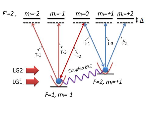
We consider co-propagating two sets of beams, say LG1 and LG2. Each set contains one LG and one Gaussian beams. Individual components of the coupled 87Rb BEC are considered to be non-rotating. The BEC is prepared in a harmonic potential using the two hyperfine states and (see FIG. 1). They are designated, henceforth, as BEC-1 and BEC-2, respectively. The interaction of the focused LG beam with the individual components of the BEC produces three angular momentum channels [43]. According to the Eq. (7), these three angular momentum channels generate +1, and 0 units of topological charge at the CM of the atom of BEC. The proper choice of polarizations of the Gaussian beams can Raman-excite the atoms to the different stoke or anti-stoke electronic states. Let us name the channels as T-1, T-2, and T-3, respectively, for BEC-1, and t-1, t-2, and t-3, respectively, for BEC-2. These three angular momentum channels correspond to the different Raman electronic transitions through the different intermediate states. For BEC-1, the channels have three intermediate electronic hyperfine states, , , and , respectively. In case of BEC-2, the intermediate electronic hyperfine states are , , and , respectively. Depending on the requirement of the problem, we can choose a particular Gaussian beam for the channel of our interest. Atoms excited by other channels will be lost from the trap due to linear momentum transferred from the focused LG beam.
A brief discussion on the interaction of the two-component BEC with the paraxial LG beams will be useful before considering non-paraxial beam in the study. However, the detailed structure of the above BEC mixture for different inter-component interactions and number of atoms along with the formalism of the interaction with paraxial LG beam are available in our recent paper [36]. The asymmetry parameter of the harmonic trap is with the axial frequency is Hz. The characteristic length is m. The intensity of the paraxial LG beam is considered, W cm-2 but the intensity of the non-paraxial LG beam before focusing is assumed 10 mW m-2 and its waist m. The intra-component -wave scattering lengths are nm, nm [1] and inter-component -wave scattering length nm, where is a parameter which can be tuned using Feshbach resonance [3, 32]. For simplicity, we consider that both the hyperfine states are populated by equal number of atoms.
3.1 Density structure of non-vortex two-component BEC revisited
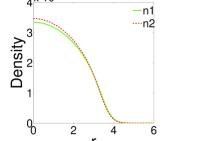
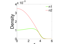
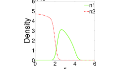
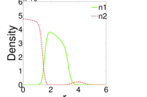
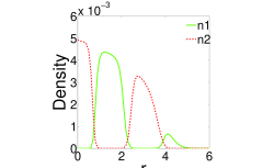
FIG. 2 presents the initial non-vortex density distribution of the two-component BEC at plane for . FIG 2(a) to 2(i) represent the distribution with increasing inter-BEC coupling strength, . Since BEC-1 has relatively stronger intra-BEC strength compared to BEC-2, BEC-1 is radially more expanded than BEC-2 at . However, this yields relatively less central density of BEC-1 compared to BEC-2 (see FIG 2(a)). As the mutual interaction between the components of BEC is increased, the components start departing from each other (FIG. 2(b) and 2(c)). Eventually after a certain value of , a part of the BEC-2 breaks and grows at the outer region of BEC-1 (FIG 2(d), 2(e), 2(f) and 2(g)). Further increase of inter-component interaction even breaks BEC-1 in some parts and it appears at the surrounding of BEC-2 (FIG. 2(h) and 2(i)). Therefore, multi-ring shaped density profiles are obtained in the x-y plane with increasing value.
3.2 Interaction with the paraxial LG beams
Let us consider that the paraxial LG1 (with OAM and SAM) and LG2 (with OAM and SAM) beams are impinged on BEC-1 and BEC-2, respectively, as shown in FIG. 1. Therefore, for both the components of the BEC, two photon Raman transitions are performed with co-propagating LG and Gaussian (G) beams based on dipole transitions. Due to the particular selection of OAM and SAM of the paraxial LG beams, only T-1 and t-1 channels will be available with one kind of Gaussian beam. The channels transfer and units of OAM to the atoms, respectively, to a particular electronic state, say, . Therefore, superposition of the vortex and antivortex states is created at the center of mass of the condensate component corresponding to the electronic state, i.e., BEC-2. To examine the effect of inter-component coupling to the T-1 and t-1 transition channels, we have studied and analyzed corresponding two-photon Rabi frequencies in FIG. 3(a). The above non-vortex density profiles are considered as initial wavefunctions of the two-components BEC. In this dipole transition, the OAM of light does not contribute to the internal motion of the atoms. Therefore, the Rabi frequencies are calculated from the multiplications of the center of mass matrix elements and the electronic matrix elements involving OAM and SAM, respectively. This has been discussed in detail in our earlier paper [36] with many distinct physical features.
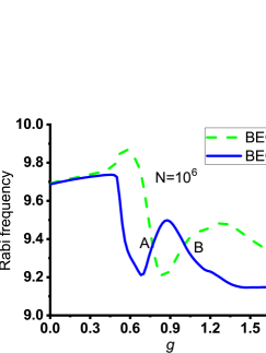
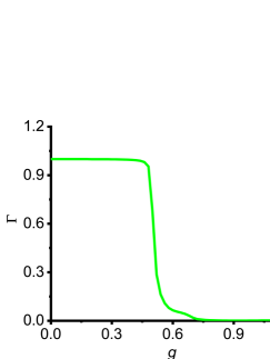
The Rabi frequency profiles of T-1 and t-1 transition channels are presented in FIG. 3(a) considering both LG1 and LG2 as paraxial. The figure interprets that BEC-1 and BEC-2 have almost the same initial density structures for -values between 0 and 0.4. Around , the local peak of Rabi frequency variation for BEC-1 in contrast to the constant descending profile of BEC-2 can be explained clearly from their initial density structures around that coupling region. Initial density profile at that -value shows that BEC-2 is compressed around the center of the trap and BEC-1 is moved away from that center. There is a coincident observed near . There the Rabi frequencies becomes locally minimum for BEC-1, but locally maximal for BEC-2. Also it is the -value at which the initial BEC components becomes totally immisible as seen from FIG. 3(b) containing the plot for variation of overlap between the components. The overlap parameter is calculated using Eq. (8) of reference [2].
| (8) |
The complete overlap, i.e. indicates total mixing between the components, whereas for complete phase separation condition we have . The cutting points A and B of the Rabi frequency distributions in FIG. 3(a) describe the population of the vortex and antivortex states at BEC-2 will be same. Therefore, these inter-component coupling strengths are ideal for a maximally coherent fringe pattern of interference. When the components are non-miscible, we may get interesting vortex-dipole dynamics [62] which is beyond the scope of discussion of this paper.
However, the interactions of the non-paraxial or focused LG beam with the two-component BEC will not only provide enhanced Rabi frequencies due to increased intensity, but also will generate different channels of transitions along with their external control mechanism as discussed in the following subsection.
3.3 Interaction with the Non-Paraxial LG beams
The interaction of the two-component BEC with the non-paraxial LG beams is the main theme of this work. The interactions open up different channels of transitions with variable strengths depending on the parameters of the LG beams. Lets chose first one of the dominant options, where before focusing the OAM and SAM of LG1 (with OAM and SAM) and LG2 (with OAM and SAM) are such that the strengths of T-1 and t-1 transitions are the strongest among each set of transitions (see FIG. 1). In fact, they are the transitions which were involved in the above mentioned paraxial case. The difference is expected to observe in the strength of Rabi frequencies and the effect of the other transition channels through which atoms are lost from the trap.
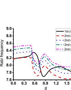
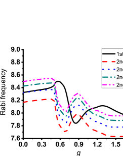
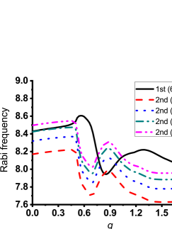
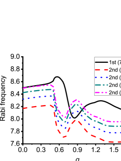
FIG. 4 shows the variation of the Rabi frequencies, calculated using expression Eq. (2.7), with the inter-component interaction strengths, of the components of BEC at different focusing angles of the LG beam. The focusing angles of LG1 are considered 40∘, 50∘, 60∘ and 70∘ in FIG. 4(a), 4(b), 4(c) and 4(d) , respectively. An overall increase in the Rabi frequencies is found with the increase in the focusing angle compared to the paraxial beam (compare with FIG. 3(a)). This is understandable as more number of photons are available for interaction with atoms trapped in the harmonic potential having a smaller cross-section compared to the paraxial beam size. In each of the plots of the FIG. 4, the focusing angles of LG2 varies from 40∘ to 70∘ in order to analyze the mutual variations of the component wise interactions.
Unlike the paraxial case, the crossing points A and B of the Rabi frequency profiles for both the components can be tuned by changing the focusing angle of the light beam. It means that the maximally coherent interference pattern can be achieved even at -value away from the A and B points obtained in the paraxial case. In other words, we will be able to estimate the focusing angles of LG1 and LG2 by observing the perfect interference pattern by tuning inter-component coupling strength of the BEC mixture. In certain combinations of focusing angles, particularly for a large difference in focusing angles between LG1 and LG2, the cutting points are not available due to the comparatively large enhancement of the average Rabi frequency for the more focused beam case (See black solid line and red dashed line in fig 4(d)).
3.4 Estimation of non-paraxial effect of LG beam through the Rabi Frequencies
To estimate the effects of the non-paraxial signature of the LG beam in interaction with the two-component BEC, one of the best approaches is to compare the strength of the side-band transitions (say, T-2 ) with the prime transition (say, t-1). Let us now consider that LG1 and LG2 are generated by focusing the paraxial beams with (OAM, SAM) = and , respectively. FIG. 5 represents the schematic diagrams of the transitions among the energy levels. Unlike the last case (see FIG. 1), T-2 transition channel couples here with the t-1 transition channel via as intermediate state. Since T-2 transition channel is only possible (between T-2 and t-1) through spin-orbit coupling of the focused LG1 beam, it is expected that the Rabi frequency profile due to this channel is strongly affected by the focusing angle of the beam. Also, we consider that Gaussian beam is used to take the atoms back to BEC-2 only when intermediate state is . Therefore, atoms, which are excited through other T-1, T-3, t-2 and t-3 channels, will be lost from the trap. Since the above selection of OAM and SAM of LG1 beam transfer unit of OAM to the atoms at BEC-1 through the T-2 channel, a vortex-antivortex superposed state is created at the electronic state of BEC-2, i.e, , with the help of two-photon Raman transition. Interestingly, the density distribution of this vortex and anti-vortex depends on the initial non-vortex structure of the BEC-2 and BEC-1, respectively.
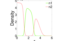
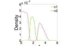
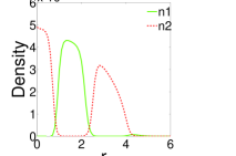
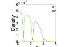
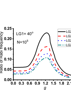
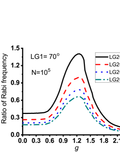
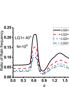
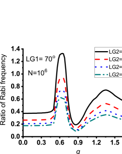
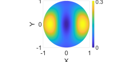
The effect of the non-paraxial nature of the LG beam on this interaction for different density of atoms can be explicit from the distribution of the ratio of Rabi frequencies of Raman transitions through T-2 and t-1 channels in FIG. 6. For example, we consider the two different populations of BEC with and . In the figures FIG. 6(a,c) and 6(b,d), we consider that the LG1 beam is focused at an angle 40∘ and 70∘, respectively. In the figures, the focusing angle of LG2 is varied from 40∘ to 70∘. The structures of the distributions definitely depend on the inter-component coupling through the initial density distributions of the BEC components. It is clear from the figures that the ratio attains a maximum value at around for and for in unit of 5.5 nm. Therefore, it is possible to enhance side-band transition significantly over primary transitions even with a comparatively low focused LG beam, if we choose the inter-component coupling strength properly. This phenomenon has a large impact on any experiments where non-paraxial vortex beam is or can be used [63]. It is obvious in the figure that at (when the components of BEC are independent of each other), strong focusing is the only possibility to increase the non-paraxial effects of the LG beam. Here, in the case of the coupled-BEC, the effects can also be controlled by specifying the intra- and inter- component interactions of the BECs. In fig 6(b,d), one can see that T-2 (which arises due to the spin-orbit coupling of light) even attains some values which is large compared to the prime transition t-1, which can not be possible in case of one-component BEC.
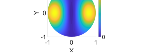
It is possible to carry out experimental study of the above effect of the non-paraxial nature in the interaction with the two-component BEC. In the above scheme of creating the vortex-antivortex superposition from the side-band and primary transitions at the energy level generates an interference pattern [43]. Let us consider that LG1 and LG2 beams are focused at angles 70∘ and 40∘, respectively, for atoms. We choose these particular combination of focusing angles of LG beams as they significantly affect the side-band transitions (see FIG. 6). The interference pattern displayed in FIG. 7 for and is in the plane. At , the populations of anti-vortex state through T-2 transition channel is much smaller compared to the population of vortex state through t-1 transition channel. In case of , the situation is opposite and both the populations from T-2 and t-1 transition are closer to each other as well. Therefore, near to maximally coherent interference pattern is produced as shown in 7(b). After fixing the focusing angles, if we tune the inter-component coupling strength of the BEC mixture, we will be able to estimate -value when effect of the non-paraxial nature of the vortex beam is maximal.
4 CONCLUSION
We have formulated a theory of interaction of the two-component BEC with the Laguerre-Gaussian (LG) beam, which is beyond the paraxial limit. Due to the coupling of the orbital and spin angular momentum of the light, the interaction of the focused LG beam with each of the components of the BEC takes place under three different angular momentum channels. Using the two photon Raman transitions, we calculate the Rabi frequencies of these angular momentum channels and show the variation of the Rabi frequency with the inter-BEC interaction strengths and focusing angles of the beam. We demonstrate the estimation procedure of the phase separation between the initial structure of the components of the BEC from the profiles of the Rabi frequencies. We have seen that the strengths of the side-band transitions achieve a maximum value for a particular value of the inter-BEC interaction strength and that is even larger than that of the strength of the primary transition for larger focusing angle of the beam. An experimental scheme is proposed to estimate the inter-coupling strength of the binary BEC by observing the coherence of the interference pattern based on the vortex-antivortex superposition from the side-band and primary transitions. Considering different orbital angular momentum of the incident beam and using the angular momentum channels, one can create multiply quantized vortices in the two-component BEC [18, 19]. These novel phenomenon of occurring multiply quantized vortices in BEC is observed in multicomponent superconductivity [64] or in rotating two-band Fermi gas [65]. The vortex-antivortex superpositions appear as the counter-rotating persistent currents in superconducting circuits [66, 67] which are propitious candidates for qubits in quantum-information processing and quantum communication networks [68]. Also, the vortices and multiple-vortices have been the subject of intensive experimental research in trapped superfluid Fermi gases [69, 70, 71] and even in real condensed matter system [72]. We believe this is one of the best approaches to study the effect of the non-paraxial nature of the vortex beam on ultra-cold atoms. This non-paraxial effects of the angular momentum channels could be experimentally verified by measuring the orbital angular momentum in the components of BEC using surface wave spectroscopy [73, 74].
ACKNOWLEDGMENTS
We thank Rohit Kishan Ray, IIT Kharagpur for useful comments on the manuscript.
References
- [1] Hall D S, Matthews M R, Wieman C E and Cornell E A 1998 Phys. Rev. Lett. 81 1543
- [2] Jain P and Boninsegni M 2011 Phys. Rev. A 83 023602
- [3] Chin C, Grimm R, Julienne P and Tiesinga E 2010 Rev. Mod. Phys. 82 1225
- [4] Nicklas E, Karl M, Höfer M, Johnson A, Muessel W, Strobel H, Tomkovič J, Gasenzer T, and Oberthaler M K 2015 Phys. Rev. Lett. 115 245301
- [5] Molony P K, Gregory P D, Ji Z, Lu B, Köppinger M P, Le Sueur C R, Blackley C L, Hutson J M, and Cornish S L 2014 Phys. Rev. Lett. 113 255301
- [6] Geurts R, Milošević M V and Peeters F M 2008 Phys. Rev. A 78 053610
- [7] McCarron D J, Cho H W, Jenkin D L, Köppinger M P and Cornish S L 2011 Phys. Rev. A 84 011603
- [8] Wacker L, Jørgensen N B, Birkmose D, Horchani R, Ertmer W, Klempt C, Winter N, Sherson J and Arlt J J 2015 Phys. Rev. A 92 053602
- [9] Wang F, Li X, Xiong D and Wang D 2016 J. Phys. B: At. Mol. Opt. Phys. 49 015302
- [10] Papp S B, Pino J M and Wieman C E 2008 Phys. Rev. Lett. 101 040402
- [11] Sabbatini J, Zurek W H and Davis M J 2011 Phys. Rev. Lett. 107 230402
- [12] Hoefer M A, Chang J J, Hamner C and Engels P 2011 Phys. Rev. A 84 041605
- [13] Hamner C, Chang J J, Engels P and Hoefer M A 2011 Phys. Rev. Lett. 106 065302
- [14] De S, Campbell D L, Price R M, Putra A, Anderson B M and Spielman I B 2014 Phys. Rev. A 89 033631
- [15] Lee C 2009 Phys. Rev. Lett. 102 070401
- [16] Kawakami T, Mizushima T, Nitta M and Machida K 2012 Phys. Rev. Lett. 109 015301
- [17] Orlova N V, Kuopanportti P and Milošević M V 2016 Phys. Rev. A 94 023617
- [18] Kuopanportti P, Huhtamäki J A M and Möttönen M 2012 Phys. Rev. A 85 043613
- [19] Kuopanportti P, Orlova N V and Milošević M V 2015 Phys. Rev. A 91 043605
- [20] Ferrier-Barbut I, Delehaye M, Laurent S, Grier A T, Pierce M, Rem B S, Chevy F and Salomon C 2014 Science 345 1035
- [21] Mertes K M, Merrill J W, Carretero-González R, Frantzeskakis D J, Kevrekidis P G and Hall D S 2007 Phys. Rev. Lett. 99 190402
- [22] Eto Y, Takahashi M, Nabeta K, Okada R, Kunimi M, Saito H and Hirano T 2016 Phys. Rev. A 93 033615
- [23] Takeuchi H, Ishino S and Tsubota M 2010 Phys. Rev. Lett. 105 205301
- [24] Law K J H, Kevrekidis P G and Tuckerman L S 2010 Phys. Rev. Lett. 105 160405
- [25] Calderaro L, Fetter A L, Massignan P, and Wittek P 2017 Phys. Rev. A 95 023605
- [26] Lercher A D, Takekoshi T, Debatin M, Schuster B, Rameshan R, Ferlaino F, Grimm R and Nägerl H-C 2011 Eur. Phys. J. D 65 3
- [27] Pasquiou B, Bayerle A, Tzanova S M, Stellmer S, Szczepkowski J, Parigger M, Grimm R and Schreck F 2013 Phys. Rev. A 88 023601
- [28] Roy A and Angom D 2015 Phys. Rev. A 92 011601
- [29] Lee K L, Jørgensen N B, Liu I K, Wacker L, Arlt J J and Proukakis N P 2016 Phys. Rev. A 94 013602
- [30] Bandyopadhyay S, Roy A, and Angom D 2017 Phys. Rev. A 96 043603
- [31] Sugawa S, Yamazaki R, Taie S and Takahashi Y 2011 Phys. Rev. A 84 011610
- [32] Inouye S, Andrews M R, Stenger J, Miesner H-J, Stamper-Kurn D M and Ketterle W 1998 Nature 392 151
- [33] Tojo S, Taguchi Y, Masuyama Y, Hayashi T, Saito H and Hirano T 2010 Phys. Rev. A 82 033609
- [34] Stenger J, Inouye S, Stamper-Kurn D M, Miesner H-J, Chikkatur A P and Ketterle W 1998 Nature 396 345
- [35] Sadler L E, Higbie J M, Leslie S R, Vengalattore M and Stamper-Kurn D M 2006 Nature 443 312
- [36] Bhowmik A, Mondal P K, Majumder S and Deb B 2018 J. Phys. B: At. Mol. Opt. Phys. 51 135003
- [37] Andersen M F, Ryu C, Cladé P, Natarajan V, Vaziri A, Helmerson K and Phillips W D 2006 Phys. Rev. Lett. 97 170406
- [38] Wright K C, Leslie L S and Bigelow N P 2008 Phys. Rev. A 77 041601
- [39] Mondal P K, Deb B and Majumder S 2014 Phys. Rev. A 89 063418
- [40] Mondal P K, Deb B and Majumder S 2015 Phys. Rev. A 92 043603
- [41] Marrucci L, Manzo C and Paparo D 2006 Phys. Rev. Lett. 96 163905
- [42] Zhao Y, Edgar J S, Jeffries G D M, McGloin D and Chiu D T 2007 Phys. Rev. Lett. 99 073901
- [43] Bhowmik A, Mondal P K, Majumder S and Deb B 2016 Phys. Rev. A 93 063852
- [44] Bhowmik A, Dutta N N and Majumder S 2018 Phys. Rev. A 97, 022511
- [45] Chu S, Bjorkholm J E, Ashkin A and Cable A 1986 Phys. Rev. Lett. 57 314
- [46] Ashkin A, Dziedzic J M, Bjorkholm J E and Chu S 1986 Opt. Lett. 11 288
- [47] Quinteiro G F and Tamborenea P I 2010 Phys. Rev. B 82 125207
- [48] Beugnon J et al. 2007 Nat. Phys. 3 696
- [49] Mehta A D, Rief M, Spudich J A, Smith D A and Simmons R M 1999 Science 283 1689
- [50] Ho T -L and Shenoy V B 1996 Phys. Rev. Lett. 77 3276
- [51] Jezek D M, Capuzzi P and Cataldo H M 2001 Phys. Rev. A 64 023605
- [52] Pu H and Bigelow N P 1997 Phys. Rev. Lett. 80 1130
- [53] Richards B and Wolf E 1959 Proc. R. Soc. London, Ser. A 253 358
- [54] Boivin A and Wolf E 1965 Phys. Rev. 138 B1561
- [55] Monterio P B, Maia Neto P A and Moysés Nussenzveig H 2009 Phys. Rev. A 79 033830
- [56] Iketaki Y, Watanabe T, Bokor N and Fujii M 2007 Opt. Lett. 32 2357
- [57] Babiker M, Bennett C R, Andrews D L and Romero L C D 2002 Phys. Rev. Lett. 89 143601
- [58] Bhowmik A, Dutta N N and Roy S 2017 Astrophys. J. 836 125
- [59] Bhowmik A, Roy S, Dutta N N and Majumder S 2017 J. Phys. B: At. Mol. Opt. Phys. 50 125005
- [60] Das A, Bhowmik A, Dutta N N and Majumder S 2018 J. Phys. B: At. Mol. Opt. Phys. 51 025001
- [61] Biswas S, Das A, Bhowmik A and Majumder S 2018 Mon. Not. R. Astron. Soc. 477 5605
- [62] Seo S W, Ko B, Kim J H and Shin Y 2017 Scientific Reports, 7 4587
- [63] Zhang J, Zhou K, Liang J, Lai Z, Yang X and Deng D 2018 Opt. Express 26 1290
- [64] Milošević M V and Perali A 2015 Supercond. Sci. Technol. 28 060201
- [65] Klimin S N, Tempere J and Milošević M V 2018 New J. Phys. 20 025010
- [66] Nakamura Y, Pashkin, Y A and Tsai J S 1999 Nature London 398 786
- [67] Friedman J R, Patel V, Chen W, Tolpygo S K and Lukens J E 2000 Nature London 406 43
- [68] Spedalieri F M 2006 Optics Communications 260 340
- [69] Zwierlein M W, Abo-Shaeer J R, Schirotzek A, Schunck C H and KetterleW 2005 Nature 435 1047
- [70] Zwierlein M W, Schirotzek A, Schunck C H and Ketterle W 2006 Science 311 492
- [71] Zwierlein M W, Schunck C H, Schirotzek A and Ketterle W 2006 Nature 442 54
- [72] Chmiel F P, Waterfield Price N, Johnson R D, Lamirand A D, Schad J, van der Laan G, Harris D T, Irwin J, Rzchowski M S, Eom C -B and Radaelli P G 2018 Nature Materials 17 581
- [73] Chevy F, Madison K W and Dalibard J 2000 Phys. Rev. Lett. 85 2223
- [74] Haljan P C, Anderson B P, Coddington I and Cornell E A 2001 Phys. Rev. Lett. 86 2922