11email: {pkouva01,dkouza01,annap,cspitsil}@cs.ucy.ac.cy 22institutetext: Department of Electrical and Computer Engineering, University of Cyprus
22email: {julio,lpetro02}@ucy.ac.cy
Formal Verification of a Programmable Hypersurface ††thanks: This work was partially funded by the European Union via the Horizon 2020: Future Emerging Topics call (FETOPEN), grant EU736876, project VISORSURF (http://www.visorsurf.eu).
Abstract
A metasurface is a surface that consists of artificial material, called metamaterial, with configurable electromagnetic properties. This paper presents work in progress on the design and formal verification of a programmable metasurface, the Hypersurface, as part of the requirements of the VISORSURF research program (HORIZON 2020 FET-OPEN). The Hypersurface design is concerned with the development of a network of switch controllers that are responsible for configuring the metamaterial. The design of the Hypersurface, however, has demanding requirements that need to be delivered within a context of limited resources. This paper shares the experience of a rigorous design procedure for the Hypersurface network, that involves iterations between designing a network and its protocols and the formal evaluation of each design. Formal evaluation has provided results that, so far, drive the development team in a more robust design and overall aid in reducing the cost of the Hypersurface manufacturing.
0.1 Introduction
This paper reports on work-in-progress carried out in the context of the research programme “VISORSURF: A Hardware Platform for Software-driven Functional Metasurfaces” [1], funded by Horizon 2020 FET-OPEN. VISORSURF is an interdisciplinary programme between computer science (networks/nano-networks and formal methods), computer engineering (circuit design and implementation), and physics (meta-materials). Its main objective is to develop a hardware platform, the HyperSurface (HSF), whose electromagnetic behavior can be defined programmatically. The HSF’s enabling technology are metasurfaces, artificial materials whose electromagnetic properties depend on their internal structure. Controlling the HSF is a network of controller switches which receives external software commands and alters the metasurface structure yielding a desired electromagnetic behavior, thus allowing a number of high-impact applications. These include electromagnetic invisibility of objects, filtering and steering of light and sound, as well as ultra-efficient antennas for sensors and communication devices.
This paper is concerned with the requirement of the programme for the rigorous design and formal evaluation of the controller-switches network and its protocols. This requirement stems from the project’s challenge to provide cutting-edge technology with limitations in both time and cost. Indeed, it is of paramount importance for the produced hardware to adhere to its specification from the very first version of the product, given the high cost of producing the components and the fact that the project’s budget is fixed. The specification includes qualitative properties, e.g., the controller network should route all messages correctly to all network nodes, as well as quantitative properties, since nodes need to be reached within specified time bounds in a fault-tolerant manner while preserving power.
Typically, in the networks literature, evaluation of network topologies and protocols is carried out via extensive simulation using discrete-event simulators such as NS-2 or OPNET, or via testbed experiments. While these are important evaluation methods, the results obtained are highly dependent on the physical-layer models supported by the simulators and, in the case of experiments, they are not suitable during the design phase of a protocol. At the same time, as is well known, the simulative approach may discover flaws in a system but it cannot prove their absence. On the other hand, formal analysis techniques allow to formally verify that a system complies to its specifications and check for the absence of flaws. Model checking, in particular, allows to investigate the behavior of a model via an exhaustive search of its state space. Properties of interest may be enunciated in temporal logic and subsequently checked for satisfaction on all possible executions of the system. In case of property violation, counter-examples can be provided to support the designer to diagnose the error. Model checking has been applied for the analysis and design of network protocols in a number of works including [3, 11, 10].
Unfortunately, a main drawback associated with model checking is the state-space explosion problem and on many occasions analysis cannot be applied on systems of a realistic size. To this effect, the use of statistical model checking (SMC) has been advocated. Statistical model checking [18, 20] is a formal-analysis approach that combines ideas of model checking and simulation with the aim of supporting quantitative analysis as well as addressing the state-space explosion problem. It uses Monte Carlo style sampling and hypothesis testing to provide evidence that a system satisfies a given property with high probability. The main idea is to simulate the system for finitely many runs and use hypothesis testing to infer whether the samples provide a statistical evidence for the satisfaction or violation of the specification. Naturally, the greater the number of simulations, the higher the precision achieved. The benefits of employing statistical model checking towards the analysis of network algorithms have been illustrated in various works including [12, 13, 8].
As required by the project’s objectives, our goal has been to develop a set of network protocols (network initialisation, routing and reporting) on a grid network (a Manhattan style topology [16] imposed by the hardware requirements of the project). In this paper we focus on the design of the routing algorithm, which proved to be the main challenge of the work. Routing within grid networks has been a topic of thorough investigation within the network community and it has been of great interest in domains such as networks on chip [9, 2]. Various algorithms have been proposed in the literature for mesh topologies where the main challenges posed were towards providing efficiency and tolerance to faults [6, 15, 17, 19]. While these works influenced the development of our routing protocol, the various restrictions imposed by the specific application, such as the limited connectivity as well as the limited resources available to each network node (e.g. limited memory/buffering space, limited computational capabilities) rendered the design of the routing algorithm quite challenging. Indeed, it turns out that apparently innocent characteristics of our model (e.g. the lack of line/column wrap-arounds) create the risk of deadlocks, even in the absence of faults in the network. To address this problem (discovered via model checking), it was necessary to explore options such as introducing buffers in the nodes or adopting different routing sequences so as to handle the congestion of parts of the network, and to seek methods for assessing these options and provide guarantees that they satisfy the set requirements.
Taking the requirements of VISORSURF into account has led us to employ formal methods from the initial stages of the iterative design of the network protocols via a continuous assessment of design proposals against requirements using model checking. Early on, our experimentation confirmed that the state-space explosion problem is a severe limitation when attempting to analyse a network of a reasonable size. Thus, we turned towards Statistical Model Checking (SMC) and we employed the UPPAAL tool and, more specifically, its SMC extension [5]. In this paper we report on our experience of applying formal methods in the design phase of a routing algorithm on a grid network as imposed by the hardware requirements of the project, and how this led to important design decisions, thus significantly facilitating us towards our goal. Furthermore, we discuss the main challenges we faced in obtaining desired results which point out directions for further research. We believe that our conclusions provide evidence on the impact formal methods may have in the design and implementation of technological applications in the context of small and medium-scale projects.
0.2 The Hypersurface: Requirements and Design Parameters
In this section we present the main requirements and design parameters of the Hypersurface, as imposed in the context of the VISORSURF programme and as needed in the present discussion. We identify three levels of requirements: i) architectural/physical constraints as imposed by the physical level of the HSF; ii) VISORSURF programme requirements as approved by the funding authority; and iii) resource/manufacturability limitations, in both time and money that make the design phase a non-trivial task.
Architectural/Physical Constraints and Terminology.
The metasurface tile is a surface consisting of configurable meta-material strips arranged as a grid. A set of four meta-material strips is configured via a controller switch, also called the intra-tile controller. All intra-tile controllers of the HSF are interconnected to constitute the intra-tile network. Intra-tile controllers will be designed and implemented as a single hardware element and their purpose is to implement basic functionalities, most importantly, support the rudimentary routing of configuration packets for configuring the metamaterial.
The intra-tile network receives configuration data from one or more gateway controllers. A gateway controller resides on the periphery of the metasurface and it sends configuration packets to controllers throughout the network that, in turn, are programmed by the user. A gateway controller has full computing power. It is envisaged that tiles will be interconnected at the gateway controller level to form larger metasurfaces.
VISORSURF Requirements.
As already explained, an intra-tile controller’s main task is to set the EM properties of the meta-material strips as directed via configuration packets from the gateway. Note that these packets are directives for appropriately implementing a desired functionality (e.g., to absorb or steer impinging waves) and, for any given function, they consist of one message per network controller. Such a set of configuration packets can be delivered in any order, thus allowing the flexibility to the gateway to decide on the sequence in which the packets will be delivered to the controller nodes. We refer to such sequences as configuration sequences.
In addition, intra-tile controllers are expected to report acknowledgements and status to the gateway, thus enabling the monitoring of the state of the controller network in real time and hence “debug” the HyperSurface program. As such, the intra-tile controller network needs to implement routing for both data and acknowledgement packets. The routing should be flexible, scalable, and robust. Furthermore, packets should be delivered in a timely manner (where the timing constraints will be determined in the course of the project). Finally, the intra-tile network needs to provide mechanisms that support a high degree of fault tolerance, where data packets will continue to be delivered to the recipient controllers despite hardware faults.
Resource/Manufacturability Limitations.
The programme is required to deliver a functioning HSF prototype within a specific amount of time, money, human, and expertise resources.
The main hardware element to be manufactured is the intra-tile controller. To limit the overall cost, a single uniform type of controller will be designed and manufactured. The selected chip technology for the controller manufacturing allows for a maximum number of 25 pins per intra-tile controller chip. The restriction limits the interconnection capabilities of an intra-tile controller with other components of the metasurface such as its connectivity with its neighbouring controllers as well as with the gateway. A consequence of this restriction is that intra-tile controllers will transmit data in a single bit-by-bit scheme. Moreover, this communication will be implemented asynchronously via an appropriate four-way asynchronous communication hardware protocol. Asynchronous communication uses no clock for synchronisation. Instead, the sender relies on the acknowledgement signal of the receiver to start and end a transmission. The restriction of asynchronous communication was imposed since adding a clock to the chip of the controller would have the following undesirable implications: i) require more components, such as a crystal that will increase the chip size, and a phase-lock loop responsible for inter-controller synchronisation; ii) increase power consumption; and iii) make a total metasurface absorber impossible because of the clock’s electromagnetic emissions. Finally, we mention that intra-tile chips will only possess volatile memory since non-volatile memory is expensive and error-prone.
0.2.1 Hypersurface Manufacturing: Iteration-
In order to mitigate the implementation risk, manufacturing of the intra-tile chip will take place in iterations. The first manufacturing iteration is expected to implement a basic but working prototype, and the entire design process will be completed for the final deliverable.
The experience presented in this paper will be implemented in the first manufacturing iteration: iteration-. Despite its basic functionality, iteration- identifies the elements that are going to be used by all future iterations: controller hardware and communication protocols, controller pin allocation, network topology, packet format, basic extendable routing protocol, and basic functionalities.
|
The initial design for iteration- can be found in Fig. 1 and Fig. 2. The three diagrams in Fig. 1 demonstrate the allocation of the pins and the communication channel endpoints on the intra-tile controller chip. Each channel endpoint requires three pins to implement bit-by-bit asynchronous communication. The limited number of pins (25) limits to a design where only four unidirectional channel endpoints can be allocated (a total of 12 pins) per controller. The physical distribution of the pins is as in diagram (b).
|
|
Following the design of the intra-tile controller, the suggestion for a grid topology is a variation of the Manhattan network topology [16] as presented in Fig. 2. Its main characteristic is that the routing direction alternates at each consecutive row and column. The topology is achieved by rotating the single design intra-tile controller by 90° each time to get the four different orientations (a-d) that are shown in Fig. 3. The interconnection of the four orientations is used to achieve the Manhattan topology; depending on the physical orientation of each intra-tile controller an output endpoint is connected to the corresponding input endpoint of a neighboring intra-tile controller. Each intra-tile controller has knowledge about its type based on its address.
The proposed topology offers a flexible and robust network, which respects the design constraints: it provides connectivity between the network nodes using only two input and two output edges per node. Unlike the Manhattan networks considered in the literature, the proposed topology provides connections (and consequently bidirectional communication) between neighbouring periphery nodes, which we refer to as wrap-arounds, thus employing all communication channels of the nodes and providing connectivity between all nodes. Our design choice of connecting neighboring periphery nodes and not the ends of each row and each column is due to the hardware implementation: crossing the interconnection wires would require to add extra layers on the PCB board that embeds the meta-surface. Furthermore, the edge controllers would require components, e.g. transistors, with more signal drive to send signals over longer wires.
Moving now to the programming of the chip, we point out that there are two modes of operation: the initialisation mode and the normal operation mode. This paper is concerned with evaluating the normal operation mode. The initialisation mode is used to initialise each intra-tile controller with a unique address and with additional initialisation data. This is necessary since, as already discussed, only a single type of controller will be produced and will not possess any non-volatile memory. This has led to the design of a simple initialisation protocol that will assign an address to each controller (its X-Y coordinates), which will be stored at its volatile memory, and, based on which each controller will determine its “type” based on its coordinates.
In the normal operation mode, due to the limited computing power of the intra-tile controller, we are experimenting with variants of the simple XY routing protocol [6], adopted for the Manhattan topology. Below there is the simple XY protocol variant adopted for the iteration- design.
The XY routing protocol assumes a Cartesian coordination system at the intra-tile controllers grid. The implementation assumes a gateway controller connected at the south west corner of the network grid and sending routing packets to intra-tile controller . The protocol first routes a packet on the -axis until it reaches the target -coordinate and then similarly on the -axis until it reaches the target. In a Manhattan topology we assume a standard mapping of the four directions “up”, “down”, “left”, “right” on each intra-tile controller depending on its orientation. Upon receiving a configuration packet, an intra-tile controller creates an acknowledgement packet to be routed to a gateway controller.
The development of the iteration- design has undergone several cycles between design and analysis. The parameters considered at each iteration include the number and position of the gateway controllers, the presence of buffer space to store received packets at each intra-tile controller as well as the capability of the controllers for parallel processing/routing of packets. The next section describe the model and the evaluation of each design following the design parameters of the topology.
0.3 Formal Evaluation
This section describes the encoding of the routing protocol in the input
language of the UPPAAL SMC model checker and its
subsequent evaluation. UPPAAL SMC is the statistical extension of
UPPAAL, a model checker for real-time systems represented by
networks of timed automata [5]. The reasons for the selection of the tool to
carry out the formal evaluation of the protocols here considered are
threefold. First, our design is associated with dense time behaviour
and requirements. Second, UPPAAL implements statistical reasoning about
properties of timed systems. Given the large state space generated by the
models, statistical model checking enables the derivation of results for
larger networks than if we had used standard model checking. Second, it
supports basic data structures expressed in the syntax of the C
programming language, thereby allowing for concise encodings of the system’s
features, e.g buffers.
0.3.1 UPPAAL SMC Models
The modelling here presented admits the following assumptions. First, the network is a grid (as discussed in the future work section parameterised model checking techniques are envisaged to enable the effective verification of larger models [4]). Second, in line with the intended operation of the system, the models account only for the routing of configuration sequences and not of arbitrary sequences of packets. Finally, given that nodes are identical (thus have the same speed) and are operating very fast, we assume the presence of a global clock and we assume that at every tick of the clock all nodes that may fire a transition will fire one transition. Following the manufacturing of the first prototype chip, timing measurements (in the form of time bounds for each operation) will be provided and encoded in the model in order to obtain a more precise timing analysis.
Table 2 summarises the system variants that have been considered during the lifetime of the iteration- design process. The basic variant is as described above and assumes a single gateway at the south-west corner of the grid. As we show below, the basic system exhibits deadlocks in routing configuration sequences. Consequently, alternative designs had to be evaluated so as to “eliminate” the deadlocks while limiting the time requirements of the routing scheme. In particular, the parallel variant assumes that nodes are equipped with a different processing unit per output. More precisely, this option is implemented in the presence of buffers within the nodes. The buffers are used to store messages received at a node until they are forwarded on the appropriate output, as per their destination node and the XY algorithm. Note, however, that such sending may fail if the recipient node is not ready to receive (e.g. because its buffer is already full). While in the basic mode the sending node will be forced to remain idle and to retry sending the message in the next time unit, in the parallel mode, and assuming there exist further messages in its buffer, the node will attempt to send a message on its other output channel, assuming that such a message exists. Note that this mode was implemented in order to explore the design possibility of implementing two independent circuits within a controller chip, one per output channel.
The acks-NE variant includes a second gateway taking input from the north-east corner of the network where the acknowledgements are routed as per the XY routing algorithm (see the topology in Fig. 2). Intuitively, this is expected to limit the congestion emerging from routing acknowledgements from north-east coordinates to south-west ones and data packets from south-west coordinates to north-east ones in the basic variant. Note that this design choice is also feasible given that multiple tiles, each with its own gateway, are expected to be interconnected in the final metasurface, offering the possibility of connecting multiple tiles to the same gateway. Finally the queue-X variant implements a queue of size for every node in the network.
| Variant | Acknowledgements | Parallel Processing | Queue size |
|---|---|---|---|
| basic | no | 0 | |
| parallel | yes | 1 (to model parallelism) | |
| acks-NE | no | 0 | |
| queue-X | no |
All system variants are given by the parallel composition of timed automata modelling the nodes, and a timed automaton (automata, respectively) representing the gateway (gateways, respectively). The communication between the nodes is encoded by means of four-dimensional adjacency matrices of pairwise communication channels, where item denotes the communication channel taking input from node and outputting to node .
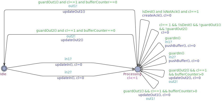
Fig. 4 depicts the timed automaton modelling the nodes. The automaton is composed of two states (locations) and ten transitions. Initially a node is in state idle. On the receipt of a message from either input in1 or in2 (, in Fig. 1(b)), the node goes to state Processing. The state models the processing of the data of the packet before the latter is routed to its destination. Whilst in this state, a node may perform either one of the following actions: (i) if it is not the destination node, then it can route the packet to one of its neighbours according to the XY algorithm; (ii) if it is the destination node, then it will create and route an acknowledgement to one of its neighbours towards a gateway (either in the south-west or the north-east corner depending on the mode of the experiment); (iii) if it is equipped with buffers, then it may receive a second packet which it enqueues in its buffer. In the figure every transition is guarded by a boolean condition determining whether or not the transition can be fired. The condition requires from the sender-receiver pair to respect the XY routing scheme and from the receiver to be in a state where the packet can be queued. Further conditions guarding the transitions enable the synchronous evolution of the system. Specifically a node can perform an action only when its local clock is equal to 1; following the action, the node resets its clock; if there is no enabled action the node simply resets its clock whenever this equals 1.
The timed automata modelling the gateways are responsible for generating configuration sequences and for receiving the acknowledgements sent by the nodes. Following the topology of the network, different orderings of the packets in a configuration sequence may induce different settings for deadlocks and time requirements in routing the sequence. We therefore consider the following configuration sequences generated by the gateway:
-
1.
. The packets are sent row by row from south to north, and the packets in a row are sent from west to east.
-
2.
. The packets are sent column by column from west to east, and the packets in a column are sent from south to north.
-
3.
. The packets are sent row by row from north to south, and the packets in a row are sent from east to west.
-
4.
. The packets are sent column by column from east to west, and the packets in a column are sent from north to south.
-
5.
. The packets are sent alternating between the and orderings at every packet sent.
Indeed, as we show below, the commitment to certain orderings can enable the implementation of simple, deadlock-free designs by building smart gateways.
0.3.2 Evaluation
We report the experimental results obtained by checking the system variants against specifications pertaining to deadlock-freedom and efficiency in routing configurations sequences:
Above, is a variable representing the number of acknowledgements that have been received whereas is a variable expressing the time taken for all acknowledgements to be received. gives the expected maximum value of whereas determines the expected maximum value of . These are calculated on the first time units, where empirical evaluation showed this to be an upper bound for the completion of the protocol, and for traces. During the lifespan of the iteration- design phase, the specifications were evaluated on progressively more complicated designs so as to derive the simplest one for which is maximised and is minimised.
| Order | System variant | ||
| basic | |||
| queue-1 | 100 | ||
| parallel | 100 | ||
| acks-NE | |||
| acks-NE-queue-1 | 100 | ||
| basic | 300 | ||
| queue-5 | 100 | ||
| parallel | |||
| acks-NE | |||
| acks-NE-queue-1 | 100 | ||
| basic | |||
| queue-5 | 100 | ||
| parallel | 100 | ||
| acks-NE | 100 | ||
| basic | 300 | ||
| queue-6 | 100 | ||
| parallel | 300 | ||
| acks-NE | 100 | ||
| basic | 300 | ||
| queue-1 | 100 | ||
| parallel | 300 | ||
| acks-NE | 100 |
Table 3 summarises the results obtained. The cells with colour demonstrate the cases where not all acknowledgements where received at the gateway, thus the case where a deadlock is present. Note that the times acquired in case of a deadlock include the deadlock traces and are thus irrelevant.
Evidently, the basic model exhibits deadlocks under all of the configuration sequence orderings. Fig. 5 (left) shows an UPPAAL-generated simulation trace showcasing a deadlock for the ordering. In the figure, node is trying to route a data packet to node through node , which in turn is trying to route an acknowledgement packet to node through node . Consequently node is waiting on node and node is waiting on node , thereby creating a deadlock.
The inclusion of queue structures in the nodes may eliminate deadlocks. Interestingly, to achieve this, different sizes of queues are required for different configuration sequence orderings, ranging from size for the and orderings, to size for the ordering. Furthermore, the routing of packets under the former orderings is more efficient. The use of parallel processing can also help to overcome deadlocks, but only in cases , , while allowing for more efficient routing in the said cases.
The routing of the acknowledgements to a second gateway attached to the norh-east corner of the network can also help alleviate the deadlocks in the , and orderings by, intuitively, reducing the congestion near the SW gateway. In the other cases, adding a queue of size is sufficient to prohibit deadlocks from occurring. Given that the size of the queues required is smaller than the corresponding cases with only one gateway, routing in the presence of two gateways appears to be more efficient.
Since the gateways are cheaper than designing and implementing queue systems and/or parallel processing capabilities, the above experimental results suggest the design of a system with two gateways as preferable for the purposes of the project. Moreover, the second gateway design offers additional flexibility and is compatible with the intended design of connecting tiles at the gateway level to form larger metasurfaces.
A point of interest regarding the acks-NE design is the nature of the deadlock as illustrated in Table 3. Fig. 5 (right) shows a part of an UPPAAL-generated simulation trace that demonstrates the deadlock in a size grid. The problem arises when a configuration packet is routed towards controller , as shown with red colour. The packet necessarily needs to be routed through controller , which is connected to the acknowledgement gateway. Also, in the problematic trace it happens that the configuration packet is interleaved with acknowledgement packets, as shown with green colour, that are routed towards controller . The interleaving creates an input/output dependency between controllers , , , and . Further experimentation revealed that the presence of deadlocks in the acks-NE design is due to similar cyclical dependencies among four interconnected controllers, where acknowledgement packets and configuration packets towards different destinations are interleaved.
Note, however, that deadlocks are removed when adding a queue of size . Moreover, further experiments carried out for different grid sizes and various configuration-sequence orderings confirmed the absence of deadlock with such a queue. Intuitively, this can be understood as follows: A queue allows for storing the interleaved packets to the receivers buffer and proceed by processing the next packet that will be sent to a different destination. In a set of nodes associated with a circular dependency, there exists at least one node (in Fig. 5 (right) node ) that cannot receive input on both of its edges. Thus, the buffer of this node will enable to break the circular dependency and allow the flow of packets along the cycle. For instance, in the example of Fig. 5 (right) the configuration packet from controller to controller can be stored in the queue of controller , thus breaking the circular dependency.
0.4 Conclusions and Future Work
The formal analysis here presented provided partial guarantees and useful insights on the behaviour of the protocols and have driven their development. These were used in iterations between designing the Hypersurface and verifying its specifications. The formal evaluation was complemented through extensive simulations via a simulator specifically built in the context of the project to support the protocol evaluation. It is worth mentioning that the formal evaluation was able to pinpoint problems in instances of the model that were not discovered by the simulator (though they were verified by it) and, additionally, the formal approach had the advantage of building models and versions of the algorithm much faster than implementing them within the simulator.
However, a number of obstacles were encountered in the process of analysing the Hypersurface. To begin with, one of the main bottlenecks was that of time. Indeed even in the context of statistical model checking, analysis of values required a non-negligible time: our experiments took up to ten minutes when run on a cluster of 12 dual-core CPUs with 24GB RAM, and this only for simulations (which by experimentation we concluded provides an acceptable estimation of the properties in question). Furthermore, also relating to the state-space explosion problem is the fact that we have to limit our analysis for specific configuration sequences, though in principle it would be useful to check algorithm correctness for arbitrary configuration sequences. Finally, the analysis of the results, in the cases where they highlighted problems in the execution of the algorithm, were difficult to interpret. Thus, in order to extract deadlocks in problematic models, it was necessary to devise additional queries which we run by standard model checking. In this respect, it would be useful if the tool could be directed to store specific traces during the analysis.
As future work, there are various directions to explore. In the context of the VISORSURF project, our efforts will continue to improve the design of the algorithms and extend the models with more details (e.g. timing information). At the same time, as the analysis metrics are being developed, further analysis will be carried out to confirm that the network complies to more detailed specifications.
In addition, as we have already pointed out, due to the state-space explosion problem our analysis is restricted by the size of the network and the packet configuration sequences. To alleviate this shortcoming, sophisticated state-space reduction techniques need to be developed, thereby enabling the effective verification of the Hypersurface. In particular we will develop parameterised model checking techniques that enable conclusions to be drawn irrespectively of the size of the network [4]. Specifically we believe the networks will admit cutoffs expressing the number of nodes that is sufficient to consider in order to conclude correctness for any number of nodes [14, 7].
Finally, the HSF design needs not only to be shown correct but also robust against adverse functioning conditions. Thus, we intend to analyse the behaviour of our design under various fault models and extend our routing protocols to fault-tolerant versions, as needed.
References
- [1] Visorsurf: A hardware platform for software-driven functional metasurfaces. http://www.visorsurf.eu/.
- [2] L. Benini and G. DeMicheli. Networks on chips: A new SoC paradigm. IEEE Computer, 35(1):70–78, 2002.
- [3] K. Bhargavan, D. Obradovic, and C. A. Gunter. Formal verification of standards for distance vector routing protocols. Journal of the ACM, 49(4):538–576, 2002.
- [4] R. Bloem, S. Jacobs, A. Khalimov, I. Konnov, S. Rubin, H. Veith, and J. Widder. Decidability of Parameterized Verification. Morgan and Claypool Publishers, 2015.
- [5] P. E. Bulychev, A. David, K. G. Larsen, M. Mikucionis, D. B. Poulsen, A. Legay, and Z. Wang. UPPAAL-SMC: statistical model checking for priced timed automata. In Proceedings of QAPL 2012, volume 85 of EPTCS, pages 1–16, 2012.
- [6] S. Chawade, M. Gaikwad, and R. Patrikar. Review of XY routing algorithm for network-on-chip architecture. International Journal of Computer Applications, 43:20–23, 2012.
- [7] E. Clarke, M. Talupur, T. Touili, and H. Veith. Verification by network decomposition. In Proceedings of CONCUR 2004, LNCS 3170, pages 276–291. Springer, 2004.
- [8] A. D. Corso, D. Macedonio, and M. Merro. Statistical model checking of ad hoc routing protocols in lossy grid networks. In Proceedings of NFM 2015, LNCS 9058, pages 112–126. Springer, 2015.
- [9] W. J. Dally and B. Towles. Route packets, not wires: On-chip interconnection networks. In Proceedings of DAC 2001, pages 684– 689. ACM, 2001.
- [10] C. Dombrowski, S. Junges, J. Katoen, and J. Gross. Model-checking assisted protocol design for ultra-reliable low-latency wireless networks. In Proceedings of SRDS 2016, pages 307–316. IEEE Computer Society, 2016.
- [11] A. Fehnker, R. J. van Glabbeek, P. Höfner, A. McIver, M. Portmann, and W. L. Tan. Automated analysis of AODV using UPPAAL. In Proceedings of TACAS, volume LNCS 7214, pages 173–187. Springer, 2012.
- [12] P. Höfner and M. Kamali. Quantitative analysis of AODV and its variants on dynamic topologies using statistical model checking. In Proceedings of FORMATS 2013, LNCS 8053, pages 121–136. Springer, 2013.
- [13] P. Höfner and A. McIver. Statistical model checking of wireless mesh routing protocols. In Proceedings of NFM 2013, LNCS 7871, pages 322–336. Springer, 2013.
- [14] P. Kouvaros and A. Lomuscio. Parameterised verification for multi-agent systems. Artificial Intelligence, 234:152–189, 2016.
- [15] M. Li, Q. Zeng, and W. Jone. DyXY: a proximity congestion-aware deadlock-free dynamic routing method for network on chip. In Proceedings of DAC 2006, pages 849–852. ACM, 2006.
- [16] N. F. Maxemchuk. Regular mesh topologies in local and metropolitan area networks. AT&T Technical Journal, 64(7):1659–1685, 1985.
- [17] A. Patooghy and S. Miremadi. XYX: A power and performance efficient fault- tolerant routing algorithm for network on chip. In Proceedings of PDP 2009, pages 245–251. IEEE Computer Society, 2009.
- [18] K. Sen, M. Viswanathan, and G. A. Agha. VESTA: A statistical model-checker and analyzer for probabilistic systems. In Proceedings of QEST 2005, pages 251–252. IEEE Computer Society, 2005.
- [19] J. Wu. A fault-tolerant and deadlock-free routing protocol in 2D meshes based on odd-even turn model. 52(9):1154 – 1169, 2003.
- [20] H. S. Younes. Verification and Planning for Stochastic Processes with Asynchrounous Events. PhD thesis, Carnegie Mellon University, 2004.