Wellcome/EPSRC Centre for Interventional and Surgical Sciences, Department of Medical Physics and Biomedical Engineering, UCL, London, UK
Centre for Medical Image Computing, Department of Medical Physics and Biomedical Engineering, UCL, London, UK
Corresponding author: brice@aeptika.co.uk
Requirements and Design Methodology for a Spatio-Angular Vitreoretinal Surgical Microscope
Abstract
This paper presents the requirements and design methodology for a vitreoretinal surgical microscope based on plenoptic imaging. The design parameters of the imaging lens, micro-lens array, and sensor are specified. The proposed design provides an extended depth imaging range when compared to proof-of-concept systems based on a commercial plenoptic sensor, and serves as the guideline for the implementation of clinically relevant surgical microscopes.
1 Introduction
Vitreoretinal surgery (VRS) takes place under high-magnification stereo microscopy that limits the attainable depth of the imaging volume, hinders D perception, and requires constant manual adjustment of microscope focus [11]. Towards improving imaging in VRS, we propose retinal observation via a plenoptic sensor, i.e. a plenoptic surgical microscope. An implementation of a plenoptic, or “light-field”, sensor is a photodetector array with a micro-lens array in front of it [16, 7]. The micro-lenses can be considered as an array of micro-cameras, each of which captures slightly overlapping micro-images. The parallax between the micro-images allows D reconstruction and computational refocusing of images and video streams [9].
Several papers and patents applications [3, 14, 4, 10, 2] showcase the interest in this imaging modality, but lack a design-driven implementation or considerations to improve image quality. The technology was evaluated as a diagnostic tools to assess the health of the human iris in vivo[5].
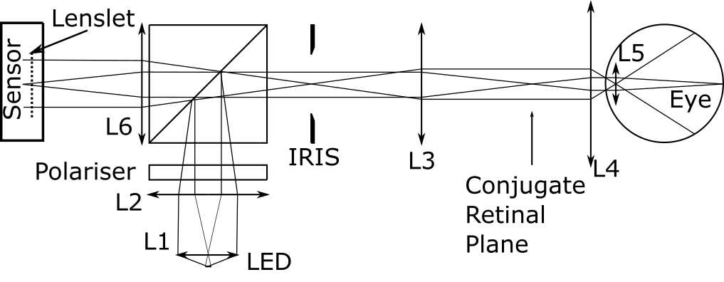
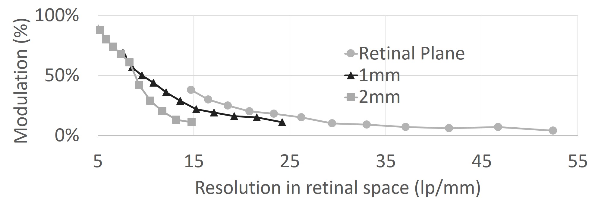
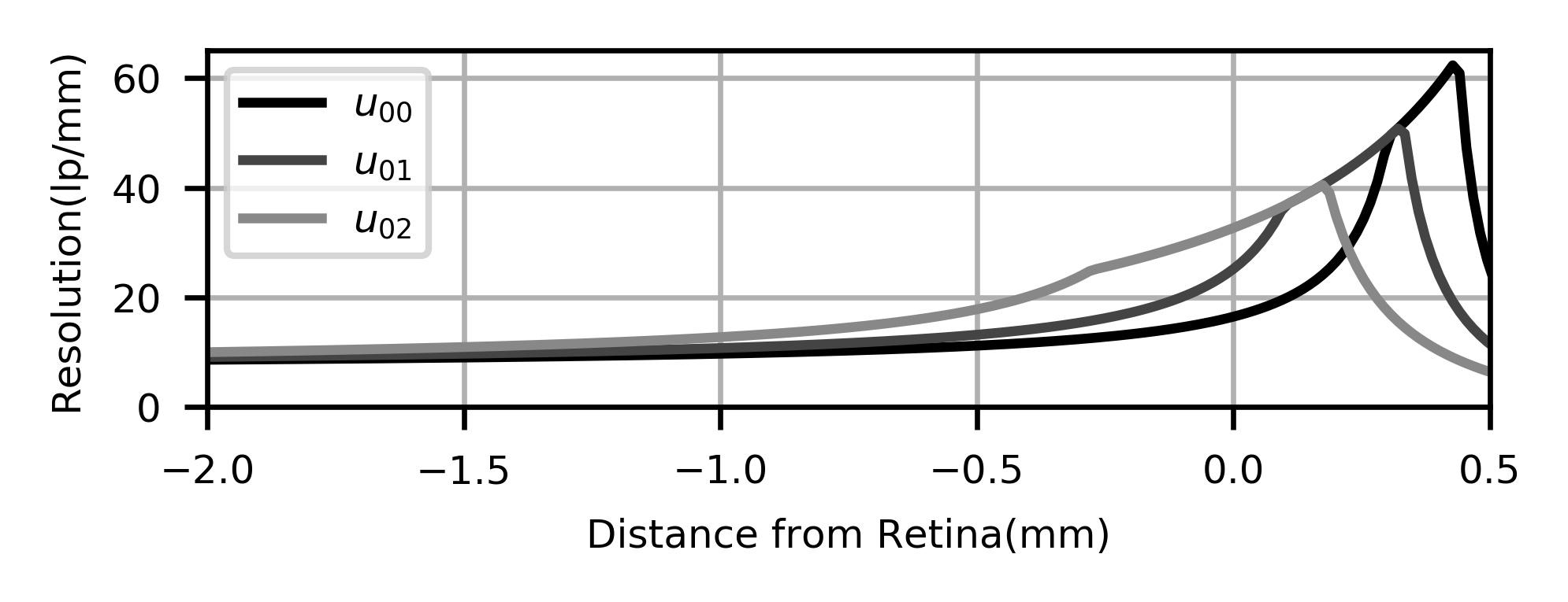
Recently, we implemented a proof-of-concept stand-alone plenoptic ophthalmoscope [13]. Its optical layout is given in Fig. 1. We used the R multi-focus plenoptic sensor from Raytrix GmbH [12], which has sets of interlaced micro-lenses, each with a different focal length. The prototype’ performance was measured following the ISO standard method[1] of imaging printed USAF Resolution Targets. Figure 2 depicts the Modulation Transfer Function (MTF) normalised at as a function of resolution of the different set bars present on the chart for the target located at a retinal plane conjugate (), mm () and mm () away from the retina. For the plane mm away from the retina the plenoptic camera can just about resolve features. We observed that the lateral resolution decreases rapidly for imaging planes further from the retina. We concluded our proof-of-concept evaluation by imaging a phantom eye with a surgical tool, and a human eye in vivo. Figure 3 shows an image of the optic disc of a Diopters myopic volunteer, acquired without manual focusing adjustment and computationally refocused post-capture.

In this letter, we present a design framework that address the limitations of this proof-of-concept system. Notably we specify the design parameters that maximize the imaging depth range of an ophthalmic plenoptic retinal imaging system without decrease in lateral resolution.
2 Design Considerations
The primary design principle for plenoptic imaging is to match the effective f-number of a micro-lens, , and of the main lens, , [15]. This constraint maximises the fill factor of the sensor while avoiding aliasing caused by overlapping micro-images.
As imaging resolution improves with smaller pupil diameters due to reduced ocular optical aberrations [18], standard retinal imaging systems limit the optical aperture to a portion of the pupil less than mm in diameter [6]. To achieve high axial resolution via plenoptic imaging, however, it is necessary to maximize the parallax among the micro-images. Therefore, the entrance aperture of the plenoptic imaging system is better set by the eye pupil’s physical size.
Perwass et al. [12] introduced the concept of “virtual depth” as the ratio of the distance between the main lens image plane and the micro-lens array, , and the distance between the sensor plane and the micro-lens array plane, , (see Fig. 4). While is fixed by the plenoptic sensor assembly, covers the range of image plane depths for which the blur spot on the sensor is smaller than the pixel size. If is the micro-lens’ diameter:
| (1) |
which, given a range of virtual depth values resolvable by the plenoptic sensor constrains focusing within .
In general, the effective imaging lens f-number of the main lens is dependent on the image distance. Therefore the matching f-number condition introduced earlier will not hold for the whole depth imaging range of the plenoptic sensor. However if the imaging lens is telecentric in imaging space, i.e. the eye pupil plane is conjugated with the front focal plane of the imaging lens, the effective imaging lens f-number () remains constant and is given by the ratio of the effective focal length of the main lens, , to the entrance pupil diameter, i.e. the diameter of the entire eye pupil, , hence e .
3 Plenoptic Imaging System Model
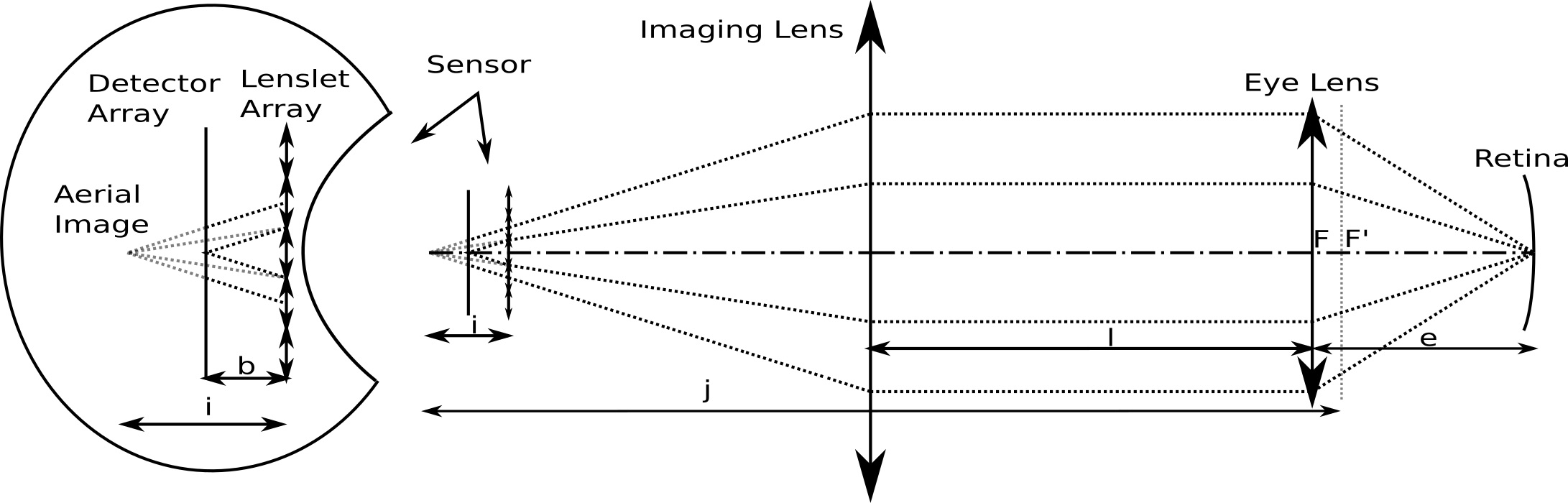
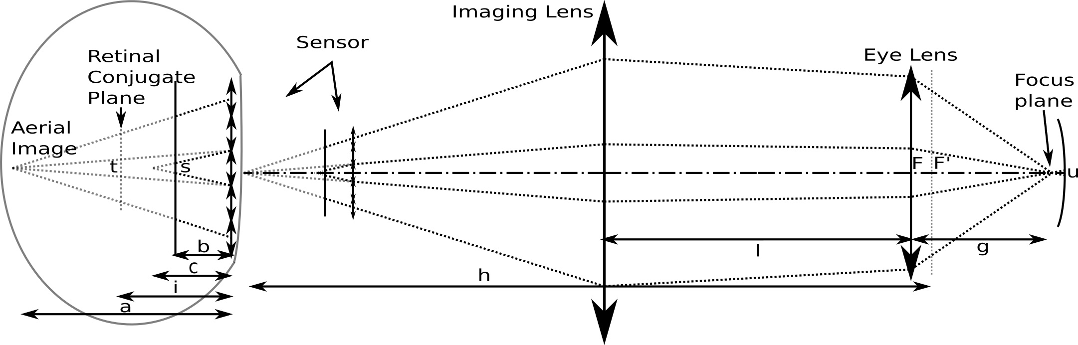
A single lens is used to model the optics of the eye in front of the retina. It is well known that the eye’s optics can be well approximated by a single lens, which merely ignores some of the higher-order aberrations. An imaging lens creates an aerial image of the retina. The micro-lens array projects multiple non-overlapping images of the retina on top of the photodetector array. Figure 4(a) shows the layout of the model with rays traced from the retinal plane coming into focus on the detector array. Figure 4(b) shows the same layout but for rays emanating from a plane in front of the retina, for which the images on the detector are slightly out of focus. The imaging lens is located a distance away from the eye to satisfy the telecentric requirements previously introduced.
The virtual image of the retina formed by the combined imaging and eye lenses is brought in focus by the micro-lenses onto the sensor. For planes at different depths, the dimension of the blur spot on the sensor, , and its projection, , in the retinal space are used to establish the depth-of-field (for clarity we omit the subscript in the figure).
As illustrated in Fig. 4, (indicated as ) corresponds to a plane being focused at a distance from the micro-lens array, where corresponds to each of different types (different focal lengths) of interlaced micro-lenses. Using similar triangles, the blur spot can be expressed as a function of the micro-lens diameter, , and the distance between the sensor and micro-lens array, :
| (2) |
The thin-lens equations for a micro-lens are
| (3) |
The f-number-matching condition is written as
| (4) |
In the telecentric configuration proposed in this letter, the effective focal length of the eye and imaging lens combination is equal to the imaging lens focal length . In Fig. 4, F and F’ represents the object and image foci respectively, the Newtonian lens equation for the Imaging lens and eye lens combination are:
| (5) |
with the equality defining the spacing between the image focus F’ and the micro-lens array:
| (6) |
We also introduce as the sensor resolution limit which is equal to twice the pixel size. The blur spot is given by the inverse magnification of the micro-lens array and the eye and imaging lens combination:
| (7) | |||||
| (8) |
where we introduced variables , with . Hence, we have variables: defining the reference retinal plane ( mm), and defining the distance from .
The plenoptic sensor design parameters , and , must be optimized so that the blur spot diameter, , is smaller than the resolution target value. The ISO standards require a resolution of for camera with a field of view , which results in m. The design problem pertains to finding the parameters that provide the largest (absolute) value of such that fulfills the ISO directives.
The multi-focus plenoptic sensor is composed of regularly spaced interlaced micro-lenses arrays of different focal lengths. When only a single micro-lens type is used, i.e. , the minimum - double covering - virtual distance required to image any point along any direction by at least two micro-lenses is equal to [12] for an hexagonal array. For , the double covering virtual distance is [12]. Finally for the next two regularly interlaced hexagonal arrays, , and , . The maximum achievable resolution in the reference plane is calculated from (8) for :
| (9) |
The resolution estimated from our model for the R sensor is shown in Fig. 5. The theoretical resolution limit quickly reduces for object planes located away from the retina within the vitreous. For plane just mm away from the retina the resolution is less than , which is in agreement with the MTF measurements reported in Sec. 1.
Considering (8), the diffraction-limit spot size can be made independent of , if the distance, , from the micro-lens array to the sensor is, with :
| (10) |
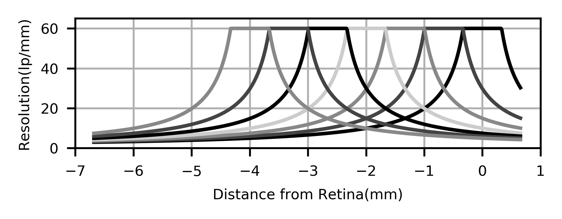
In that case, it can be shown that (8) reduces to (9). Using the condidtion of equation 10 into our model, we display in figure 6, the resolution curve we expect to get with a 7-types hexagonal lenslet array. We select the design parameter of the plenoptic sensor in order to achieve a constant lateral resolution of for an imaging volume with a depth of more than .
4 Discussion
We present a telecentric configuration in this letter. Equation 9 shows that for a given pixel size of the sensor and target resolution the diameter of the lenslet is fixed and evolve linearly with the pixel size of the sensor. Using equation 10 and , we can calculate the imaging lens image distance from the lenslets array and from equation 4 we calculate the focal length of the imaging lens. We plot the evolution of and against the pixel size of the sensor in figure 7, where we can notice that for pixel size above a certain value the effective focal length of the imaging lens get smaller than . For example for a 7-types hexagonal array, a sensor with a pixel size larger than m will require an imaging lens with a back focal length longer than its effective focal length, otherwise know as reverse telephoto or retrofocus lens [17].
An alternative design to the telecentric configuration presented in this letter is to conjugate the eye lens and imaging lens. A unit magnification relay telescope can be use for this purpose, effectively making both imaging lens and eye lens acting as one. In this alternative configuration, equations 9 and 10 become respectively:
| (11) | |||
| (12) |
We plot in figure 7, the corresponding evolution of and . Here we can see that for all pixel size the effective focal length remain larger than . This configuration is suboptimal in terms of matching the f-number across the whole imaging depth, but it might significant simplify the design of the imaging lens. In the plenoptic literature the increase of the effective f-number for plane located at various distance within the imaging volume has not been considered or discussed.
![]()
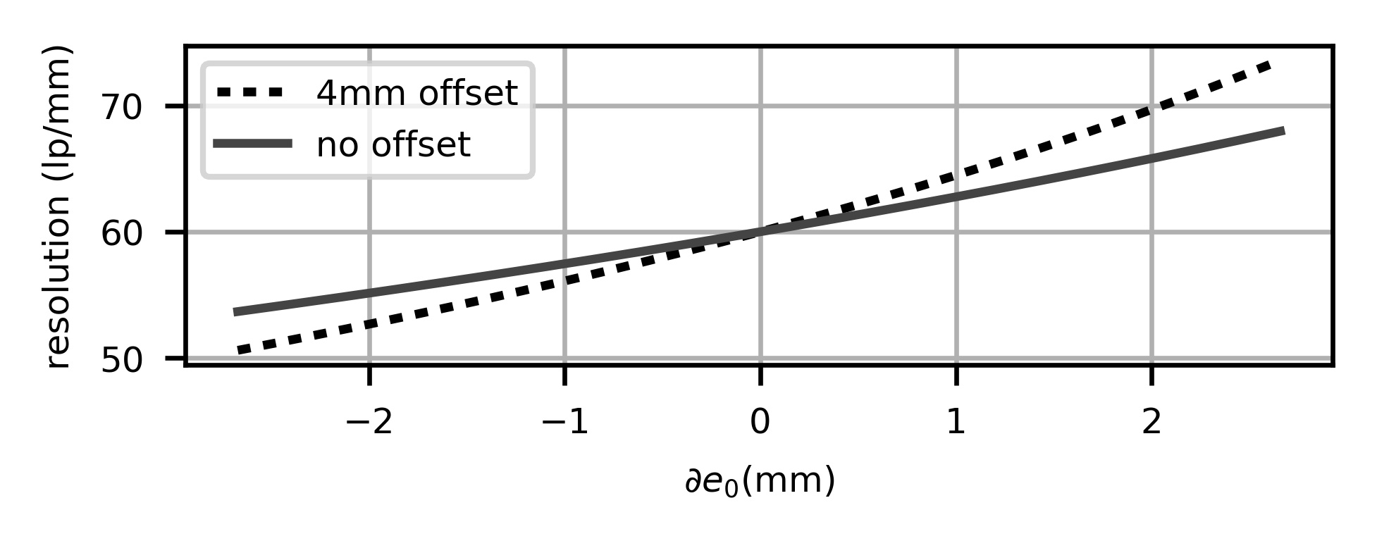
The effective focal length and dimension of vitreous humour in human eyes vary among person. A recent study [8] shows a maximum variation of mm across the population. We estimated the effect of this inter-subject variability on the image resolution of the proposed design by taking the derivative of equation 8. Figure 8 shows the resolution change for the retinal plane and for a plane offset by mm from the retina which corresponds to the depth extent of the imaging volume as seen in figure 6.
5 Conclusions
In this letter we proposed a design approach for retinal imaging with a constant lateral resolution across an extended depth imaging range which is significantly larger than what is currently achievable with a stereo microscope without manual focusing. We established the first order properties and requirements for a plenoptic ophthalmic imaging system. The presented methodology paves the way for the implementation of such clinically-relevant systems.
Acknowledgements
We acknowledge the support of Fight for Sight [1728/29] and the Academy of Medical Sciences [SBF001/1002]. Further, we thank Peter West (UCL Institute of Ophthalmology) for providing necessary equipment.
References
- [1] Ophthalmic intruments – Fundus cameras. British Standard BS EN ISO 10940:2009.
- [2] Niels Abt, A. Ophthalmic surgery using light-field microscopy, October 2015.
- [3] Murtaza K. Adam, Weston Aenchbacher, Timothy Kurzweg, and Jason Hsu. Plenoptic Ophthalmoscopy: A Novel Imaging Technique. Ophthalmic Surgery, Lasers and Imaging Retina, 47(11):1038–1043, November 2016.
- [4] Noah Bedard, Lingfei Meng, Vipin Namboodiri, Krishna Prasad Agara Venkatesha, and Kathrin Berkner. Simultaneous capture of filtered images of the eye, November 2014.
- [5] Hao Chen, Maria A. Woodward, David T. Burke, V. Swetha E. Jeganathan, Hakan Demirci, and Volker Sick. Human iris three-dimensional imaging at micron resolution by a micro-plenoptic camera. Biomedical Optics Express, 8(10):4514, October 2017.
- [6] Edward A. DeHoog. Novel fundus camera design. PhD, University of Arizona, 2009.
- [7] Ivo Ihrke, John Restrepo, and Lois Mignard-Debise. Principles of Light Field Imaging: Briefly revisiting 25 years of research. IEEE Signal Processing Magazine, 33(5):59–69, September 2016.
- [8] Dong Hwan Kim, Jin-Sun Jun, and Ryul Kim. Ultrasonographic measurement of the optic nerve sheath diameter and its association with eyeball transverse diameter in 585 healthy volunteers. Scientific Reports, 7(1), December 2017.
- [9] Edmund Y. Lam. Computational photography with plenoptic camera and light field capture: tutorial. Journal of the Optical Society of America A, 32(11):2021, November 2015.
- [10] Matthew Everett Lawson and Ramesh Raskar. Methods and apparatus for retinal imaging, March 2014.
- [11] Yasser Helmy Mohamed, Masafumi Uematsu, Daisuke Inoue, and Takashi Kitaoka. First experience of nDASEK with heads-up surgery: A case report. Medicine, 96(19):e6906, May 2017.
- [12] Christian Perwass and Lennart Wietzke. Single lens 3d-camera with extended depth-of-field. In IS&T/SPIE Electronic Imaging, pages 829108–829108. International Society for Optics and Photonics, 2012.
- [13] Brice Thurin, Edward Bloch, Pearse Keane, Sotiris Nousias, Christos Bergeles, and Sebastien Ourselin. Retinal fundus imaging with a plenoptic sensor. In Fabrice Manns, Per G. Söderberg, and Arthur Ho, editors, Ophthalmic Technologies XXVIII, volume 10474, page 1047429, San-Francisco, February 2018. SPIE.
- [14] Alexandre Tumlinson, R. and Matthew Everett, J. Light Field Camera for Fundus Photography, July 2011.
- [15] Massimo Turola. Investigation of plenoptic imaging systems: a wave optics approach. PhD thesis, City University London, 2016.
- [16] Andreas Tünnermann, Sylvia Gebhardt, and Henning Fouckhardt. Plenoptic Cameras. In Hans Zappe and Claudia Duppe, editors, Tunable Micro-optics, pages 417–438. Cambridge University Press, Cambridge, 2016.
- [17] Anthony Vella and Julie Bentley. Extreme retrofocus zoom lens for single-shot single-lens HDR photography and video. In Zoom Lenses V, volume 9580, page 95800G. International Society for Optics and Photonics, 2015.
- [18] A. B. Watson. Computing human optical point spread functions. Journal of Vision, 15(2):26–26, February 2015.