∎
Tel.: +421-55-792-2201
Fax: +421-55-633-62-92
44email: clovecko@saske.sk
Study of the non-linear dynamics of micro-resonators based on a Sn-whisker in vacuum and at mK temperatures
Abstract
The dynamics of micro-resonators (or any mechanical resonators) can be studied by two complementary methods allowing the measurements in two different domains: (i) in the frequency domain - by the frequency sweeps using cw-excitation, and (ii) in the time domain - by the pulse techniques, when the free-decay oscillations are investigated. To broaden the knowledge about the intrinsic mechanical properties of micro-resonators based on a Sn-whisker we used both methods. We show that the dynamics of the Sn-whisker can be described by a phenomenological theory of the Duffing oscillator. Furthermore, we present the results of theoretical analysis based on the Duffing’s model provided in the time and frequency domains, and we show that these results are qualitatively the same with those measured experimentally.
Keywords:
micro-resonators tin whiskers pulse-demodulation technique Duffing oscillator1 Introduction
Following the significant technological advancements in a semiconductor device fabrication, as a direct consequence of a very popular trend to downscale integrated electronic circuits, the physical size of mechanical resonators was successfully reduced to micro- and nanometer range NEMS-Ekinci . The motion of such resonators is usually measured by a coupled electronic circuit, thus composing a micro-electromechanical (MEMS) or nano-electromechanical systems (NEMS). Due to their high sensitivity and simple implementation, these devices have found many commercial applications (e.g. mass sensing NEMS-mass , frequency standards NEMS-Clock , analogue frequency filters NEMS-Filt ).
When the resonator’s dimensions are reduced, the energy related to its surface states grows and becomes comparable with the energy stored in its inner volume. Simultaneously, the resonator’s surface breaks several symmetries due to which non-linear effects are gained and emphasised. These effects change the resonator’s dynamics and affect the intrinsic processes of the energy dissipation and exchange between the resonator and surrounding thermal bath, forming new mechanisms and channels of the energy transfer NEMS-Deco1 ; NEMS-Deco2 . To investigate these processes, we decided to construct a novel type of micro-resonator based on readily available Sn-whiskers Whisker1 . These metallic fibres with diameter up to 1-2 m and 1 mm in length grows usually on the stressed surfaces of tin alloys Whisker2 ; Whisker3 ; Whisker4 . Among the principal advantages of Sn-whisker belong that it is a single crystal, characterised by a relatively smooth surface, [0 0 1] as a preferred growth direction WhiskerGrowth , high tensile strength (720 - 880 MPa vs 220 MPa in a bulk tin) and Young’s modulus close to the bulk value WhiskerMech . Moreover, it becomes superconducting at temperature K. As our measurements were performed in vacuum, at temperatures mK and magnetic field mT, one can expect that our resonator will have a reasonably high Q-factor.
2 Experimental details
 |
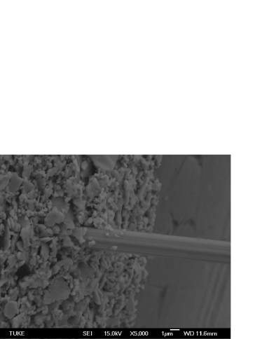 |
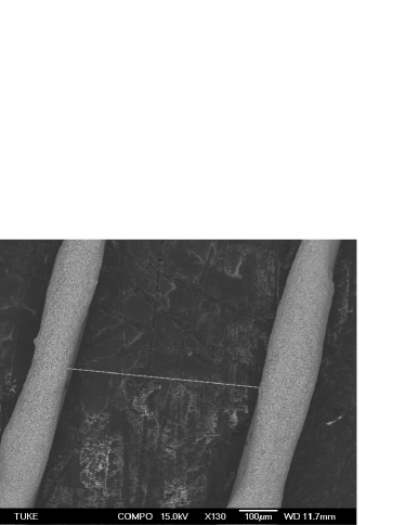
In order to construct the micro-resonator based on Sn-whisker, a relatively simple whisker holder needs to be manufactured WhiskerPaper . Firstly, two parallel copper wires of 100 m in diameter are glued 0.5 mm apart on a graph paper impregnated by the Stycast 1266 epoxy resin. The same substance is then used to attach the whole structure to a small piece of thin copper sheet with a surface insulated by a cigarette paper to ensure a good thermal and electrically non-conductive contact between both parts. The respective pairs of the copper wires are twisted and in order to protect them, a sleeve made of nylon fishing line is applied. Finally, the Sn-whisker can be positioned carefully on the finished whisker holder and secured on its place by a conductive silver epoxy resin (fig. 1). The whisker holder has a convenient mounting hole, so it can be mounted easily on the silver experimental plate. Placed in the middle of strong superconducting magnet and thermally connected to the mixing chamber of the commercially available cryogen free dilution refrigerator, this experimental set-up allows us to perform measurements in the magnetic fields up to 8 T and at temperatures down to 10 mK.
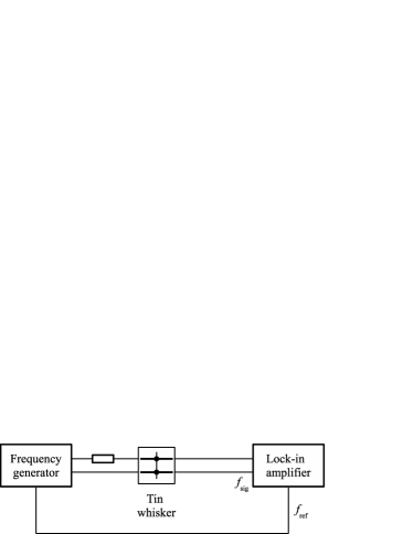
The physical properties and dynamics of micro- and nano-resonators are usually studied in the frequency domain by the traditional technique of frequency sweeps with continuous voltage/current excitation (fig. 2 left). A precise function generator serves as a current source and the response of Sn-whisker based micro-resonator in the form of induced voltage is measured by a phase-sensitive (Lock-in) amplifier. Its reference signal is provided by the same function generator, so the both response components can be determined. As we are dealing with the forced oscillations driven by excitation at given frequency, the dynamics of micro-resonator based on Sn-whisker is studied in the frequency domain.
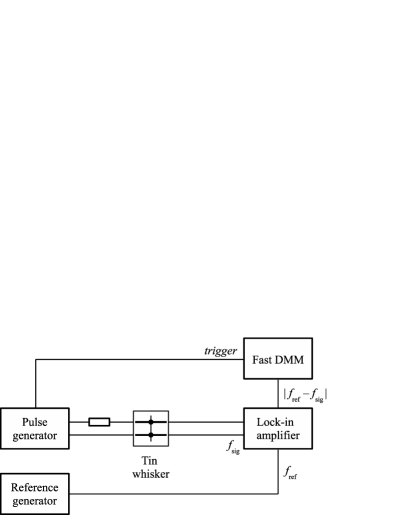
There is a complementary measurement method represented by a pulse technique when the free damped oscillations are examined in the time domain. If the corresponding FFT spectrum is calculated, the dynamics of micro- and nano-resonators can be transformed to the respective frequency domain and results can be compared to the frequency sweeps measurements. We have utilised a novel type of the pulse-demodulation technique (fig. 2 right) implemented successfully for the quartz tuning forks PulseTech . In contrast to the frequency sweeps technique there is an additional precise function generator providing the reference signal at frequency for the Lock-in amplifier. Moreover, a fast DMM is connected to the output of Lock-in amplifier and used for the data acquisition and storage. At first, the excitation pulse is applied at frequency for N periods. At the end of excitation pulse the fast DMM is triggered and the signal of free damped oscillations (originally at ) is being measured at differential frequency .
 |
 |
3 Experimental results and discussion
As it was shown during the previous frequency sweeps measurements WhiskerPaper , the response of Sn-whisker based micro-resonator becomes non-linear even at the moderate current excitations. The resonant curve is tilted towards the lower frequencies and as the current excitation increases this tendency becomes more prominent. Our new experimental results confirm that when a critical excitation is exceeded, the direction of frequency sweep starts to play an important role and as a result, the effect of hysteresis is observed (fig. 3). Clearly, there is a frequency region where the resonator can oscillate either with high or low velocity amplitude depending on the sweep’s history.
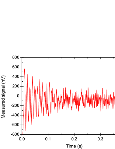
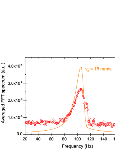
To deepen our understanding about the intrinsic mechanical properties of micro-resonator based on Sn-whisker, we studied its response in the time domain by the means of pulse-demodulation technique. The frequency of excitation pulse Hz was chosen to be near the resonant frequency . There are two parameters of excitation pulse which can be adjusted in order to obtain a reasonable signal-to-noise ratio: the number of periods and the pulse amplitude . It is worth to note that due to a low signal-to-noise ratio the amplitude of excitation pulse was significantly larger () than during the frequency sweeps measurements. Similarly, the number of periods was set to . The resulting signal of free damped oscillations is shown in a fig. 4 left. To improve the corresponding FFT spectrum, the pulse measurement for given parameters , and was repeated 20 times, individual FFT spectra were determined and, finally, the average FFT spectrum was calculated (fig. 4 right). As the signal of free damped oscillations is being measured at differential frequency the whole FFT spectrum is transposed to the lower frequency range. Moreover, the FFT spectrum is not symmetrical and higher frequencies are more pronounced.
 |
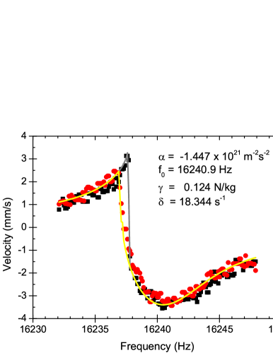 |
The response of Sn-whisker based micro-resonator during the frequency sweeps measurements resembles the behaviour of Duffing oscillator, especially at higher current excitations. In general, the motion of forced Duffing oscillator can be described by a following ordinary differential equation
| (1) |
where represents damping, is the resonant angular frequency, determines the resulting non-linearity of the restoring force and is the amplitude of a harmonic driving force normalized per unit mass and acting at the angular frequency . This equation is not analytically solvable; however, there are many mathematical methods available which allow to find an approximate steady-state solution. Using the homotopy analysis HomotopyAnal or harmonic balance method HarmBalance , it is possible to derive the expressions for displacement amplitude and phase
| (2) | |||||
| (3) |
As a side note, there is a special case , when the frequency response of Duffing oscillator has the same shape of Lorentzian function as for the linear harmonic oscillator. The same is true for the case of small driving forces when , i.e. in the linear regime, then the quality factor Q of our micro-resonator can be determined as well. The result is in the excellent agreement with our previous measurements WhiskerPaper .
 |
 |
By analysing the equation (2) for the displacement amplitude , it is possible to determine the angular frequency when the response of Duffing oscillator is maximal
| (4) |
As one can see, the response of Duffing oscillator at the higher amplitudes of displacement is no longer linear. The resonance curve is not symmetrical any more and depending on the sign of , there is an effect of softening (for ) or hardening (for ) observed. Moreover, at even larger displacement amplitudes, the response of oscillator will depend on the direction of frequency sweep itself and is characterised by a hysteresis behaviour with distinctive abrupt changes in the amplitude of oscillations.
In principle, the expression (2) is a cubic equation for and can be solved numerically for the given parameters , , and . Once a computational algorithm for the calculation of is available, the relation (3) can be used to determine . Moreover, by implementing the well-known Levenberg-Marquardt method Levenberg ; Marquardt ; Leven-Marq , it is possible to construct a software (numerical) fitting function for the experimentally measured dependencies. In our case, the coefficients , , and serve as the initial guess parameters for our fitting function. In addition, the experimental data from the up and down frequency sweeps are being processed at the same time and, finally, the best fit parameters are determined. The computed results (represented by the solid lines in fig. 3) confirm a definite agreement between the measured experimental data and calculated fit.
Now, we apply the model of Duffing oscillator for the theoretical description of the free damped oscillations of Sn-whisker based micro-resonator, with parameters , and determined from the frequency sweeps measurements. In this case, the right-hand side of equation (1) is equal to zero (no driving force is applied). In order to simplify the necessary numerical calculations, the fourth-order Runge-Kutta method was chosen with the initial conditions selected as and . The resulting signal was calculated up to 0.5 s time interval and the corresponding FFT spectrum was determined and then transposed to the lower frequency range by subtracting the reference frequency . For initial velocity mm/s, there is a reasonable qualitative agreement between measured and simulated FFT spectra (see fig. 4 right, the solid line represents the simulated FFT spectrum). Knowing the initial induced voltage amplitude nV (see fig. 4 left), it is possible to estimate as well. For the whisker of mm length placed in the magnetic field of 20 mT, the resulting order of magnitude estimate for the initial velocity is mm/s. This agrees quite well with the simulated value of 15 mm/s.
4 Conclusions
To conclude, we studied the dynamics of micro-resonator based on Sn-whisker by measuring its response in both (frequency and time) domains. Besides the traditional measurement method - the frequency sweeps using continuous excitation, the modified pulse-demodulation technique was proposed and implemented. Moreover, the phenomenological theory of Duffing oscillator applied to the micro-resonator’s response in the frequency domain resulted in the excellent qualitative agreement between the experimental data and corresponding fits. Using the known values of fitting parameters , and , obtained from the implemented Duffing’s theory, the free damped oscillations were calculated and the corresponding FFT spectra were compared to the averaged FFT spectra determined from the resonator’s response in the time domain. As it was shown, there is a qualitative agreement between them. Thus, we have proved a one-to-one qualitative correspondence between measurements in time and frequency domains.
Acknowledgements.
We would like to thankfully acknowledge the support by grants APVV 14-0605, VEGA 2/0157/15 and European Microkelvin Platform. The financial support provided by the U. S. Steel Košice s.r.o. is also gratefully recognised and highly appreciated.References
- (1) K. L. Ekinci, M. L. Roukes, Nanoelectromechanical systems, Rev. Sci. Instrum. 76, 061101 (2005)
- (2) J. Chaste, A. Eichle, J. Moser, G. Ceballos, R. Rurali, A. Bachtold, A nanomechanical mass sensor with yoctogram resolution, Nature Nanotechnol. 7, 301 (2012)
- (3) C. Lam, A review of the recent development of MEMS and crystal oscillators and their impacts on the frequency control products industry, Proc. IEEE Ultrasonics Symp., pp. 694 – 704 (2008)
- (4) S.-S. Li, Y.-W. Lin, Z. Ren, and C.-C. Nguyen, An MSI Micromechanical Differential Disk-Array Filter, Solid-State Sensors, Actuators and Microsystems Conference 2007, pp. 307 – 311 (2007)
- (5) L. G. Remus, M. P. Blencowe, Y. Tanaka, Damping and decoherence of a nanomechanical resonator due to a few two-level systems, Phys. Rev. B 80, 174103 (2009)
- (6) O. Maillet, F. Vavrek, A. D. Fefferman, O. Bourgeois, E. Collin, Classical decoherence in a nanomechanical resonator, New J. Phys. 18, iss. 7, 073022 (2016)
- (7) K. G. Compton, A. Mendizza, S. M. Arnold, Filamentary growths on metal surfaces—“whiskers”, Corrosion 7, 327 (1951)
- (8) R. M. Fisher, L. S. Darken, K. G. Carroll, Accelerated growth of tin whiskers, Acta Metal. 2, 368 (1954)
- (9) G. T. Gaylon, A History of a Tin Whisker Theory: 1946 to 2004, iNEMI. Freely available on http://thor. inemi.org/webdownload/newsroom/Presentations/SMTAI-04_tin_whiskers.pdf
- (10) Y. Sun, E. N. Hoffman, P.-S. Lam, X. Li, Evaluation of local strain evolution from metallic whisker formation, Scr. Mater. 65, 388 (2011)
- (11) W. J. Choi, T. Y. Lee, K. N. Tu, N. Tamura, R. S. Celestre, A. A. MacDowell, Y. Y. Bong, Luu Nguyen, Tin whiskers studied by synchrotron radiation scanning X-ray micro-diffraction, Acta Materialia 51, 6253 (2003)
- (12) S. S. Singh, R. Sarkar, H.-X. Xie, C. Mayer, J. Rajagopalan, N. Chawla, Tensile Behavior of Single-Crystal Tin Whiskers, J. Electron. Mater. 43 (4), 978 (2014)
- (13) M. Človečko, E. Gažo, S. Longauer, E. Múdra, P. Skyba, F. Vavrek, M. Vojtko, Vacuum Measurements of a Novel Micro-resonator Based on Tin Whiskers Performed at mK Temperatures, J. Low Temp. Phys. 175, 449 (2014)
- (14) M. Človečko, M. Grajcar, M. Kupka, P. Neilinger, M. Rehák, P. Skyba, F. Vavrek, High Q value Quartz Tuning Fork in Vacuum as a Potential Thermometer in Millikelvin Temperature Range, J. Low Temp. Phys. 187, 573 (2017)
- (15) F. Tajaddodianfar, M. R. H. Yazdi, H. N. Pishkenari, Nonlinear dynamics of MEMS/NEMS resonators: analytical solution by the homotopy analysis method, Microsystem Technologies. 23, 1913 (2017) https://doi.org/10.1007/s00542-016-2947-7
- (16) D. W. Jordan, P. Smith, Nonlinear ordinary differential equations – An introduction for scientists and engineers (4th ed.), pp. 223–233, Oxford University Press, (2007) ISBN 978-0-19-920824-1
- (17) K. Levenberg, A Method for the Solution of Certain Problems in Least Squares, Quart. Appl. Math. 2, pp. 164-168 (1944)
- (18) D. Marquardt, An Algorithm for Least-Squares Estimation of Nonlinear Parameters, SIAM J. Appl. Math. 11, pp. 431-441 (1963)
- (19) P. R. Gill, W. Murray, M. H. Wright, The Levenberg-Marquardt Method, §4.7.3 in Practical Optimization. London: Academic Press, pp. 136-137 (1981)